Marklin Digital 60883 User manual

2
Inhaltsverzeichnis:
Seite
Bestimmungsgemäße Verwendung 4
Sicherheitshinweise 4
Wichtige Hinweise 4
Ein- und Ausgänge des Link 88 4
Anschluss 5
Anschluss Übersicht 6
Konfiguration des L88 8
Nutzung als Tasten-Matrix 12
Table of Contents:
Page
Using the Product as Intended 14
Safety Notes 14
Important Notes 14
Inputs and Outputs for the Link 88 14
Connect 15
Overview of Connections 16
Configuration for the L88 18
Use as a Button Matrix 22
Sommaire :
Page
Utilisation conforme à sa destination 24
Remarques importantes sur la sécurité 24
Information importante 24
Entrées et sorties du Link 88 24
Connectez 25
Vue d’ensemble des branchements 26
Configuration du L88 28
Utilisation comme matrice de touches 32
Inhoudsopgave :
Pagina
Beoogd gebruik 34
Veiligheidsvoorschriften 34
Belangrijke aanwijzing 34
In- en uitgangen van de Link 88 34
Aansluiten 35
Aansluit overzicht 36
Configuratie van de L88 38
Benutten als drukknoppen-matrix 42

3
Indice de contenido:
Página
Uso correcto 44
Instrucciones de seguridad 44
Notas importantes 44
Entradas y salidas del Link 88 44
Montaje 45
Esquema sinóptico de conexionado 46
Configuración del L88 48
Uso como matriz de teclas 52
Indice del contenuto:
Pagina
Impiego commisurato alla destinazione 54
Avvertenze per la sicurezza 54
Avvertenze importanti 54
Entrate e uscite del Link 88 54
Collegamento 55
Panoramica delle connessioni 56
Configurazione dello L88 58
Utilizzo come matrice di tasti 62
Innehållsförteckning:
Sidan
Användning av produkten 64
Säkerhetsanvisningar 64
Viktig information 64
In- och utgångar på Link 88 64
Anslutning 65
Översikt: Anslutninga 66
Konfiguration av L88 68
Användning som knapp-matris 72
Indholdsfortegnelse:
Side
Hensigtsmæssig anvendelse 74
Sikkerhedshenvisninger 74
Vigtige bemærkninger 74
Ind- og udgange på Link 88 74
Tilslutning 75
Tilslutningsoversigt 76
Konfiguration af L88 78
Anvendelse som tastematrix (kontrolpanel) 82

4
deut.
Ein- und Ausgänge des Link 88
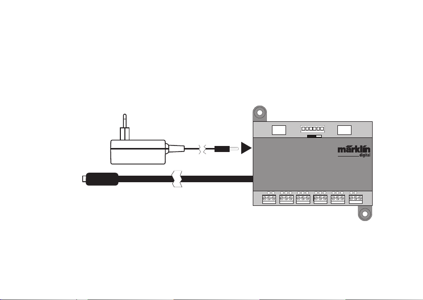
Stromversorgung: Schaltnetzteil 66360 oder 66201.
Anschluss an Central Station / Terminal
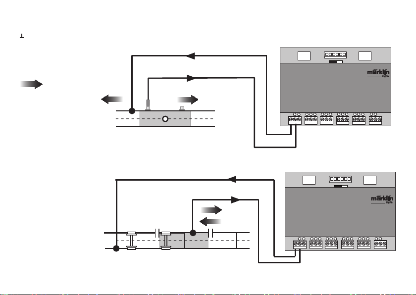
Masserückführung (bei Verwendung als Rückmelder)
1-16 Kontaktanschluss (Märklin H0 Mittelleitergleis
oder Taster)
Bus 1 60881 oder 60882
Bus 2 60881 oder 60882
Bus 3 60880 und/oder 6088
Schalter für Stromversorgung der S88 Module mit 5V oder 12V.
Bestimmungsgemäße Verwendung
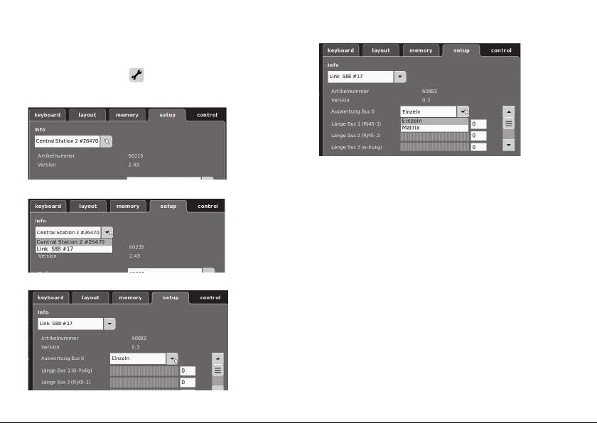
• Das Rückmeldemodul L88 ist für den Anschluss an die
Central Stationen (CS3) 60216/60226, (CS2) 60213/60214/
60215 ab der Software Version 3.8.xx und höher bestimmt.
•
Anschluss der Rückmeldemodule 6088 (S88)/60880 (S88)/60881
(S88 AC) und 60882 (S88 DC) an oben genannte Central Station.
• Das Rückmeldemodul L88 Link ist ein Rückmelder mit 16
Meldekontakten für das Märklin H0-Mittelleitergleis oder
2L Gleise (Spur 1, Trix H0, Minitrix) mit Reed Kontakten
• Bzw. Anschluss bis zu 64 Taster.
Sicherheitshinweise
• Die Spannungsversorgung des L88 Link erfolgt aus-
schließlich über das Schaltnetzteil 66360 oder 66201.
• Anschlussarbeiten am Rückmeldemodul L88 Link dürfen
nur im spannungslosen Zustand erfolgen.
• ACHTUNG! Funktionsbedingte scharfe Kanten und Spitzen.
• Das Gehäuse darf nicht geöffnet werden.
• Das Rückmeldemodul L88 Link ist ausschließlich zum
Gebrauch in trockenen Räumen bestimmt.
Wichtige Hinweise
• Die Bedienungsanleitung ist Bestandteil des Produktes
und muss deshalb aufbewahrt sowie bei Weitergabe des
Produktes mitgegeben werden.
• Für Reparaturen wenden Sie sich bitte an Ihren Märklin-
Fachhändler.
• Gewährleistung und Garantie gemäß der beiliegenden
Garantieurkunde.
• Entsorgung: www.maerklin.com/en/imprint.html
12 3 45678
T
T
910 11 12 13 14 15 16
Bus 1 Bus 2Bus 3
12V 5V
S88 Link
60880/6088
60881/60882 60881/60882
Central Station /
Terminal
Stromversorgung
66360 oder 66201
Masserück-
führung Gleis oder Taster
Schalter Stromver-
sorgung S88/S88AC/
S88DC
Masserück-
führung

5
12 3 45678
T
T
910 11 12 13 14 15 16
Bus 1 Bus 2Bus 3
S88 Link
12V 5V
Central Station /
Terminal
Anschluss
Anschluss an die Central Station
Den Link 88 direkt an den Boosteranschluß der CS2 oder an das Terminal 60145
anschließen, danach die Stromversorgung 66360 oder 66201 einstecken.

6
12 3 45678
T
T
910 11 12 13 14 15 16
Bus 1 Bus 2Bus 3
S88 Link
12 3 45678
T
T
910 11 12 13 14 15 16
Bus Bus
S88 AC
12 3 45678
T
T
910 11 12 13 14 15 16
Bus Bus
S88 DC
decoder s 88
87654321
910111213141516
12V 5V
Max. 31x S88
Max. 31x
S88 AC oder DC
Max. 31x
S88 AC oderDC
An einen Link 88 können maximal 31 S88 und/oder 62
S88AC/S88DC angeschlossen werden.
Bus 1
Bus 2
Bus 3
CS2 / CS3 oder Terminal
Stromversorgung 66360 / 66201
Anschluss Übersicht Ein bestehender Anschluss des S88 an der
Central Station 2 kann beibehalten werden
Schalter Stromversorgung
S88/S88AC/S88DC = 5V/12V
(Siehe nächste Seite)

7
Pin S88 Name Beschreibung Pin RJ45 Farbe
EIA/TIA 568A
1DATA Auslesedaten 2 grün
2GND Masse für Signale und Versorgungsspannung 3 weiss/orange
2GND 5 weiss/blau
3 CLOCK Taktsignal für die Synchronisation 4 blau
4PS (LOAD) Lade die Informationen in den Bus 6 orange
5 RESET Zurücksetzen der Eingangsspeicher 7 weiss/braun
6 +5V/+12V Versorgungsspannung für die Rückmeldemodule 1 weiss/grün
—SHIELD Kabelabschirmung, nicht angeschlossen — —
PIN Belegung Pin RJ45
Märklin übernimmt keine Haftung bei gemeinsamer Nutzung von Märklin Produkten und Produkten anderer Anbieter. Wir empfehlen
daher dringend die PIN Belegungen des RJ45 Steckers zu prüfen.
Stromversorgung:
5V im Mischbetrieb von Märklin S88 und S88 AC/DC (wie in Abb. dargestellt), sowie Produkten anderer Anbieter.
12V nur in Verbindung S88 AC/DC. Bei einer Stromversorgung mit 12V wird die Störanfälligkeit verringert.

8
jetzt können die einzelnen Daten eingestellt werden.
• Auswertung Bus 0 (direkter Bus des L88),
Einstellung Einzeln = 16 Melde Kontakte
Einstellung Matrix = bis zu 64 Taster
• Länge Bus 1-3
Hier wird eingetragen wieviel S88 an jedem Bus ange-
schlossen sind (max. 31).
• Zykluszeit Bus 1-3
Abfragezyklen der S88 Busse in ms (min 10ms - max. 1000 ms)
eintragen (werkseitig 100ms).
• Bitzeit S88
Einstellen Zyklus der Antwort (werkseitig 167µs)
• Zykluszeit (Link 88) Kontakt 1 - 16
Abfragezyklus der Link Kontakte bei Verwendung als Gleis-
kontakt 1 - 16.
• Zykluszeit Tastastatur
Abfragezyklus bei Verwendung als Tastatur (werkseitig 67ms).
• Spalten (Ausgang) Tastatur
Eintragen der Spalten (max. 8) der Tastatur Matrix
• Zeilen (Eingang) Tastatur
Eintragen der Zeilen (max. 8) der Tastatur Matrix
Konfiguration des L88
Vor Inbetriebnahme des L88 muss dieser erst konfiguriert
werden. Dazu gehen Sie in der CS auf setup/Info, nun mit
dem Symbol Werkzeug
Dazu gehen Sie in der CS auf setup/Info, nun mit
in den Konfigurationsmodus. Alle
nachfolgende Abbildungen sind Beispiele:
klappen sie die Info aus
Wählen sie Link S88 #17,

9
Adressierung der Module:
Die Module adressieren sich durch das Einstecken automa-
tisch. Für die Einstellungen in der Central Station finden Sie
nachfolgend die Adresssen.
Kontakte (Gleis): 1-16
Tasteradressen: 101-164
Bus 1: 1001 -1496 (z.B. 1005 = 1. Modul, Kontakt 5)
Bus 2: 2001 - 2496
Bus 3: 3001 - 3496
Beispiele von Einstellungen an der Central Station:
Einstellungen an der Central Station:
1. Nutzung als Gleiskontakt:
1.1 Verwendung im Memory (Beispiel):
gehen Sie in Konfigurationsmodus
Über Button Erw. in
die erweiterte Einstel-
lung springen.
Angemeldetes
Gerät auswählen
z.B. Kontakt 8
Modul 2
Bus 2
1.2 Verwendung im Layuot (Beispiel):
gehen Sie in Konfigurationsmodus und definieren den
Kontakt
Adresse (Kontakt)
eingeben
Gerät auswählen
Funktion wählen,
wenn erforderlich
Gerätetausch.
Wird ein Gerätetausch notwendig, kann der neue L88 auf die
bisherige Gerätenummer umgestellt werden. Die Umstellung
erfolgt nach Anmeldung des Link 88 in der CS unter setup -
Werkzeug - Geräte - bearbeiten. Geben Sie dort dem neuen
Link 88 ihre bisherige Gerätenummer ein und bestätigen
Sie dieses. Danach ist ein Neustart der CS notwendig, nun
funktionieren alle Kontakte wie gewohnt.

10
12 3 45678
T
T
910 11 12 13 14 15 16
Bus 1 Bus 2Bus 3
12V 5V
12 3 45678
T
T
910 11 12 13 14 15 16
Bus 1 Bus 2Bus 3
12V 5V
S 88 Link
S 88 Link
Beispiele für den Anschluss der verschiedenen Melde-Kontakte
Masserückführung für alle Gleis-Kontakte nur 1x erforderlich.
Anschluss an das Märklin
H0-Gleissystem mit dem
Schaltgeis
= Meldende Fahrt-
richtung
Fahrtrichtungsabhängige
Meldung.
Anschluss an das Märklin
H0-Gleissystem mit Kon-
taktgleisen
Fahrtrichtungsunabhän-
gige Meldung

11
12 3 45678
T
T
910 11 12 13 14 15 16
Bus 1 Bus 2Bus 3
12V 5V
12 3 45678
T
T
910 11 12 13 14 15 16
Bus 1 Bus 2Bus 3
12V 5V
S 88 Link
S 88 Link
Anschluss an das Märklin
H0-Gleissystem mit Reedkontakt.
Fahrtrichtungsunabhängige
Meldung
Anschluss an Zweileiter-Gleis-
systeme, unabhängig von der
Spurgröße nur mit Reedkontakt.
Fahrtrichtungsunabhängige
Meldung
Masserückführung ist pro Reed-Kontakt erforderlich

12
Nun muss jeder Taste eine Fahrstraße zugeordnet werden.
Achten Sie darauf, dass die Fahrstraßen im Memory auf
Automatik-Betrieb eingestellt sind. Die Einstellungen erfolgen
im Konfigurationmodus des Memory (siehe Anleitung der Central
Station).
Die Zuordnung erfolgt über die Taste in den erweiterten
Einstellungen für Fahrtstrasse.
Geben sie zuerst die Adresse der Taste ein (Tabelle S.13).
Anschluss Stellpult
Es können max. 8 Stellpulte (Eingang 9 - 16) angeschlossen
werden.
9
1
2
3
4
72720 / 72729 / 7272
10
5
6
7
8
Eingang
Ausgang
Kontakt 1-8 (Ausgang/
Spalten)
Kontakt 9-16 (Eingang/Zeilen)
1
2
3
4
9
10
11
12
Nutzung als Tasten-Matrix (Stellpult):
Wollen Sie den L88 für eine Tasten-Matrix verwenden, dann
müssen folgende Einstellung vorgenommen werden.
Durch die Einstellung Matrix können max. 64 Taster (32 Ma-
gnetartikel oder 64 Fahrstraßen) unterstützt werden. Für den
Aufbau wird pro Taster zusätzlich eine Diode 1N4148 benötigt,
Einbaurichtung beachten.

13
1 (Ausgang)
9
10
11
12 Taste 1 = 101
2 (Ausgang)
Taste 2 = 102
Adressierung der Tasten (Beispiele)
(Eingang)
Danach das zugeordnete Gerät (hier 17) eintragen.
Ist alles richtig eingetragen, bestätigen Sie es mit dem
grünen Haken. Auf dem jetzt im Display erscheinenden Bild
mit dem blauen Pfeil zwischen speichern. Danach weitere
Fahrstraßen bearbeiten oder mit dem grünen Haken
bestätigen und beenden.
Taster
1 - 8
9 - 16
18 - 24
25 - 32
9 10 11 12 13 14 15 16
1 101 109 117 125 133 141 149 157
2 102 110 118 126 134 142 150 158
3 103 111 119 127 135 143 151 159
4 104 112 120 128 136 144 152 160
5 105 113 121 129 137 145 153 161
6 106 114 122 130 138 146 154 162
7 107 115 123 131 139 147 155 163
8 108 116 124 132 140 148 156 164
Ausgang
Eingang
Adresstabelle für die Tasten
Bitte beachten, die Diode muss in Sperrrichtung zum Ausgang
eingebaut sein.
Beispiel Taster 1: Eingang 9 angeschlossen an Ausgang 1 erhält
die Adresse 101.
1 (Ausgang)
9
(Eingang)
Taste 9 = 109
Taste 25 =125
Taste 26 = 126

14
Using the Product as Intended
• The L88 feedback module is designed for connection to
the 60216/60226 (CS3) and the 60213/60214/60215 Central
Stations (CS2) with Software Version 3.8.xx and higher.
•
Connections from the 6088/60880/60881 and 60882 feedback
modules to the Central Station units mentioned above.
•
The L88 Link feedback module is a position indicator with 16
indicator contacts for Märklin H0 center conductor track or
for 2-rail track (1 Gauge, Trix H0, Minitrix) with reed contacts.
• Or connections to 64 button controllers.
Safety Notes
• The voltage supply for the L88 Link is done only by means
of the 66360/66367 or 66201 switched mode power pack.
• Connections to the L88 Link feedback module may only be
done with no voltage present.
• WARNING! Sharp edges and points required for operation.
• The housing must not be opened.
• The L88 Link feedback module is designed only for use in
dry areas.
Important Notes
• The operating instructions are a component part of the
product and must therefore be kept in a safe place as
well as included with the product, if the latter is given to
someone else.
• Please see your authorized Märklin dealer for repairs
• The warranty card included with this product species
the warranty conditions.
• Disposing: www.maerklin.com/en/imprint.html
12 3 45678
T
T
910 11 12 13 14 15 16
Bus 1 Bus 2Bus 3
12V 5V
S88 Link
Inputs and Outputs for the Link 88
Current supply: 66360/66367 or 66201 switched mode power pack.
Connections to the Central Station / Terminal
Ground return (when used as a position indicator)
1-16 Contact connections (Märklin H0 center conductor
track or button controllers)
Bus 1 60881 or 60882
Bus 2 60881 or 60882
Bus 3 60880 and/or 6088
Switches for current supply to the S88 Module with 5 volts
or 12 volts.
Central Station /
Terminal
Current supply
66360 or 66201
US only: 66367
Ground Return Track or Button
Controller Ground
Return
Switches for current
supply
S88/S88AC/ S88DC
60880/6088
60881/60882 60881/60882

15
12 3 45678
T
T
910 11 12 13 14 15 16
Bus 1 Bus 2Bus 3
S88 Link
12V 5V
Central Station /
Terminal
Connect
Connections to the Central Station
Connect the Link 88 directly to the Booster connection on the CS2 or to the 60145
Terminal. After that plug in the 66360/66367 or 66201 power supply.

16
12 3 45678
T
T
910 11 12 13 14 15 16
Bus 1 Bus 2Bus 3
S88 Link
12 3 45678
T
T
910 11 12 13 14 15 16
Bus Bus
S88 AC
12 3 45678
T
T
910 11 12 13 14 15 16
Bus Bus
S88 DC
decoder s 88
87654321
910111213141516
12V 5V
Maximum
31 x S88
Maximum 31 x
S88 AC or DC
A maximum of 31 S88 units and/or 62 S88AC/S88DC
units can be connected to a Link 88.
Bus 1
Bus 2
Bus 3
CS2 / CS3 or Terminal
Current supply 66360+ 60822
US only: 66367
Overview of Connections
Maximum 31 x
S88 AC or DC
An existing connection from the S88 to the
Central Station 2 can be kept.
Switches for current supply
S88/S88AC/ S88DC = 5V/12V
(see next page)

17
S88 Pin Name Description PIN RJ45 Color
EIA/TIA 568A
1DATA Readout Data 2 green
2GND Ground for signals and voltage supply 3 white/ orange
2GND 5 white/blue
3 CLOCK Clock signal for the synchronization 4 blue
4PS (LOAD) Load the data into the bus 6 orange
5 RESET Reset the input memory 7 white/brown
6 +5V/+12V Voltage supply for the feedback module 1 white/green
—SHIELD Cable shield, not connected — —
PIN Assignment for the RJ45 Plug
Märklin assumes no liability for joint use of Märklin products and products of other makes.
We therefore urgently recommend that you check the PIN assignments of the RJ45 plug you may be using.
Current Supply:
5volts in mixed operation of S88 and S88 AC/DC Märklin products (as shown in the illustration), as well as products of other
makes.
12 volts only in conjunction with the S88 AC/DC. The susceptibility to interruptions is reduced with a 12 volt power supply.

18
Now the individual data can be set..
• Evaluation of Bus 0 (direct bus for the L88),
Setting for individual units = 16 indicator contacts
Setting for matrix = up to 64 button controllers
• Length of Bus 1-3
Here you enter how many S88 units are connected to
each bus (max. 31).
• Cycle period for Bus 1-3
Enter query cycles for the S88 busses in milliseconds (ms)
(min 10 ms - max. 1000 msm, factory setting 100 ms).
• Bit time for the S88
Set the cycle for the answer (factory setting 167 µs)
• Cycle period for (Link 88) Contacts 1 - 16
Query cycles for the Link contacts when used as track
contacts 1 - 16.
• Cycle period for keyboard
Query cycle when used as a keyboard (factory setting 67 ms).
• Columns for the keyboard
Entering the columns (max. 8) for the keyboard matrix
• Rows for the keyboard
Entering the rows (max. 8) for the keyboard matrix
Configuration for the L88
The L88 must first be configured before using it for the first
time.
To do this go into the CS to setup/Info and with the tool
symbol
To do this go into the CS to setup/Info and with the tool
go into the configuration mode. All of the following
images are examples:
Open up Info
Select Link S88 #17.

19
Addresses for the Module:
The module automatically get an address when it is plugged
in. You will find below the addresses for settings in the
Central Station.
Contacts (track): 1-16
Button controller addresses: 101-164
Bus 1: 1001 -1496 (ex. 1005 = 1st module, Contact 5)
Bus 2: 2001 - 2496
Bus 3: 3001 - 3496
Examples of Settings on the Central Station:
Settings on the Central Station:
1. Use as a track contact:
1.1 Use in the Memory (example)
Go into the Configuration mode
Jump over Button
to the advanced
setting.
Select a registered
device
e.g. Contact 8
Modul 2
Bus 2
1.2 Use in the Layout (example)
Go into the Configuration mode and define the contact
Enter address
(contact)
Select device
Select function, if
necessary
Swapping Devices.
If a device swap becomes necessary, the new L88 can be
switched to the previous device number. The switch takes
place after the Link S88 registers in the CS at setup –Tool
–Devices - edit. Enter the new Link S88 there with the
previous device number and confirm this number. After that,
the CS needs to be rebooted. All of the contacts will function
as usual.

20
12 3 45678
T
T
910 11 12 13 14 15 16
Bus 1 Bus 2Bus 3
12V 5V
12 3 45678
T
T
910 11 12 13 14 15 16
Bus 1 Bus 2Bus 3
12V 5V
S 88 Link
S 88 Link
Sample Connections for the Different Feedback Contacts
Only one ground return is required for all track contacts.
Connections to the Märklin
H0 track system with the
Circuit Track
= Direction of tra-
vel feeding back
Feedback is dependent on
the direction of travel
Connections to the Märklin
H0 track system with
Contact Tracks
Feedback is independent
of the direction of travel
Other manuals for 60883
1
Table of contents
Languages:
Other Marklin Digital Toy manuals
Popular Toy manuals by other brands

Lionel
Lionel 390E Operator's manual

Eduard
Eduard Ju 88A-4 exterior Assembly instructions

Fisher-Price
Fisher-Price Imaginext DNY07 manual

The Cool Tool
The Cool Tool PLAYMAT instruction manual

LEGO
LEGO MindStroms Bug Book 9735 Building instructions

Hasbro
Hasbro Disney STAR WARS LUKE SKYWALKER Electronic Green... manual