marklin 260 V 60 User manual

Modell der
Baureihe 260/261 (V 60)

2Vorbild • Prototype • Exploitation dans le réel • Grootbedrijf
Informationen zum Vorbild
Zu dem umfangreichen Neubeschaffungsprogramm
an Diesel-Lokomotiven bei der Deutschen Bundes-
bahn in den 50er-Jahren des 20. Jahrhunderts, zu
denen zum Beispiel auch die V 100 und V 200 als
zwei sehr populäre Baureihen gehörten, wurde für
den Rangierdienst die dreiachsige Rangierlokomotive
der Baureihe V 60 in großer Zahl beschafft.
Mit einer Leistung von 650 PS erreichte diese Lok
eine Spitzengeschwindigkeit von 60 km/h. Ange-
trieben über eine Blindwelle mit Kuppelstangen ist
diese Lok einer der letzten Konstruktionen, die diese
optisch so beeindruckende Art der Kraftübertragung
besitzt. Die sich bewegenden Kuppelstangen stellen
eben die visualisierte Dynamik dar.
Ab 1968 wurden diese Modelle in BR 260 umbe-
nannt. Später wurde ein Großteil der Modelle mit
Fernsteuerung ausgestattet und als Kleinlokomotive
eingestuft. Dadurch durften auch angelernte Rangier-
kräfte diese Rangierlokomotive steuern.
Information about the prototype
The extensive new diesel locomotive program on
the German Federal Railroad in the 1950s included
the popular classes V 100 and V 200. The class V 60
3-axle diesel
switch engine was ordered in large
quantities for switching work.
This locomotive had a power output of 650 hp and
reached a maximum speed of 60 km/h or 38 mph. It
was powered by a jackshaft with side rods and was
one of the last designs to have this visually impres-
sive form of power transmission. The side rods in
motion represent by themselves the dynamic motion
of the locomotive.
Starting in 1968 this model was reclassified as
the class 260. Later a large number of these models
were equipped for remote control and were grouped
as small locomotives. This made it possible for even
newly trained switch engine crews to control these
units.

3
Vorbild • Prototype • Exploitation dans le réel • Grootbedrijf
Informations concernant la locomotive réele
Dans le cadre de l’ambitieux programme de renou-
vellement des moyens de traction diesel développé
par la Deutsche Bundesbahn au cours des années
cinquante du siècle passé, lequel comprenait entre
autres la fourniture des très populaires séries V 100 et
V 200, on a commandé un grand nombre de machines
de manoeuvre à trois essieux de la série V 60.
Développant une puissance de 650 CV, cette loco-
motive pouvait atteindre la vitesse de 60 km/h. Cette
machine, dotée d’un moteur entraînant les essieux au
moyen d’un faux-essieu et de bielles d’accouplement,
était une des dernières constructions munies d’un tel
dispositif d’entraînement au fonctionnement assez
impressionnant.
A partir de 1968, la série V 60 est devenue la série
260. Une grande partie des machines a été dotée par
la suite d’un équipement de télécommande et classées
dans la catégorie des petites locomotives, ce qui a
nécessité la formation d’ouvriers qualifiés pour leur
pilotage.
Informatie van het voorbeeld
Tot het omvangrijke aankoopprogramma van nieuwe
diesellocomotieven bij de Deutschen Bundesbahn
in de vijftiger jaren van de 20ste eeuw, waartoe ook
bijvoorbeeld de populaire serie V 100 en V 200 be-
hoorden, werd voor de rangeerdienst de drie-assige
rangeerlocomotief serie V60 in grote aantallen aange-
kocht.
Met een vermogen van 650 pk bereikte de loc een
topsnelheid van 60 km/h. Aangedreven door een zgn.
”blindwiel” en koppelstangen is deze loc één van
de laatste constructies die deze op het oog indruk-
wekkende wijze van krachtoverbrenging bezit. De
bewegende koppelstangen geven nu eenmaal een
dynamisch beeld.
Vanaf 1968 werden deze modellen omgenummerd
in de serie 260. Later werd een groot deel van de
machines voorzien van een afstandsbesturing en
als locomotor aangemerkt. Hierdoor mochten ook
daarvoor opgeleide rangeerders deze locomotieven
besturen.

4Betrieb • Operation • Fonctionnement • Exploitatie
Funktion
Diese Lokomotive mit eingebauter Mehrzug-Elektronik
bietet:
• Wahlweise Betrieb mit Gleichstrom (max ± 18 V=), Wech-
selstrom (Märklin Transformer 32 VA), Märklin Delta (nur
Delta Station 6607), Märklin Digital (nur Control Unit) oder
Märklin Systems (Mobile Station, Central Station). Ein Be-
trieb mit anderen Betriebssystemen (Impulsbreitensteue-
rung, Central Control 1 etc.) ist nicht möglich.
• Die Betriebsart wird automatisch erkannt.
• 80 Mehrzugadressen (davon 4 für das Delta-System) ein-
stellbar. Eingestellte Adresse ab Werk: 61 + 62
• Veränderbare Anfahrverzögerung (ABV).
• Veränderbare Bremsverzögerung (ABV).
• Veränderbare Höchstgeschwindigkeit.
• Einstellen der Lokparameter elektronisch über Control
Unit, Mobile Station oder Central Station.
• Eingebaute Geräuschelektronik, nur im Betrieb mit Control
Unit oder Märklin Systems nutzbar. Zusätzliche schaltbare
Geräusche.
• Das Modell ist für den Betrieb auf Märklin 1 – Gleisen ent-
wickelt. Ein Betrieb auf anderen Gleissystemen geschieht
auf eigenes Risiko.
• Befahrbarer Mindestradius: 600 mm
• Das
Modell besitzt vorne und hinten jeweils eine Telex-
kupplung, mit der im Digital-/Systems-Betrieb Märklin
1-Modelle mit Klauenkupplungen
per Schaltbefehl
abgekuppelt werden können. Bei Verwendung von
Kupplungssystemen anderer Hersteller sind Betriebspro-
bleme nicht ausgeschlossen.
• Bis auf die Stirnbeleuchtung sind die Funktionen in den
Betriebsarten Gleichstrom, Wechselstrom und Märklin
Delta ausgeschaltet.
Die bei normalem Betrieb anfallenden Wartungsarbei-
ten sind nachfolgend beschrieben. Für Reparaturen oder
Ersatzteile wenden Sie sich bitte an Ihren Märklin-Fach-
händler.
Jegliche Garantie-, Gewährleistungs- und Schadensersatzansprüche
sind ausgeschlossen, wenn in Märklin-Produkten nicht von Märklin freigege-
bene Fremdteile eingebaut werden und / oder Märklin-Produkte umgebaut
werden und die eingebauten Fremdteile bzw. der Umbau für sodann auf-
getretene Mängel und/ oder Schäden ursächlich war. Die Darlegungs- und
Beweislast dafür, dass der Einbau von Fremdteilen oder der Umbau in bzw.
von Märklin-Produkten für aufgetretene Mängel und / oder Schäden nicht ur-
sächlich war, trägt die für den Ein- und / oder Umbau verantwortliche Person
und / oder Firma bzw. der Kunde.
Sicherheitshinweise
• Die Lok darf nur mit einem dafür bestimmten Betriebs-
system (Gleichstrom, Märklin Wechselstrom-Transfor-
mator 6647, Märklin Delta, Märklin Digital oder Märklin
Systems) eingesetzt werden.
• Die Lok darf nur aus einer Leistungsquelle gleichzeitig
versorgt werden.
• Beachten Sie unbedingt die Sicherheitshinweisein der
Gebrauchsanleitung zu Ihrem Betriebssystem.

5
Betrieb • Operation • Fonctionnement • Exploitatie
Schaltbare Funktionen 6647 6021
STOP
mobile station
systems
60652 60212
Stirnbeleuchtung fahrtrichtungsabhängig Dauernd ein 1) 61/ function + off2) Licht-Taste Taste bei Symbol
Betriebsgeräusch - 61/f2 2) Taste bei Symbol Taste bei Symbol
Geräusch: Signalhorn - 61/f3 2) Taste bei Symbol Taste bei Symbol
TELEX-Kupplung -61/f4 2) Taste bei Symbol Taste bei Symbol
Rangiergang (nur ABV) -62/f1 2) Taste bei Symbol Taste bei Symbol
Geräusch: Pressluft -62/f2 2) Taste bei Symbol Taste bei Symbol
Geräusch beim Kuppeln -62/f3 2) Taste bei Symbol Taste bei Symbol
1) => Intensität abhängig von der Höhe der Versorgungsspannung.
2) => 61 = 1. Adresse, 62 = 2. Adresse

6Betrieb • Operation • Fonctionnement • Exploitatie
Lokparameter mit
der Control Unit
einstellen
1. Voraussetzung: Aufbau
wie Grafik 1. Nur die zu
verändernde Lok ist auf
dem Gleis.
2. „Stop“- und „Go“-Tas-
te gleichzeitig drücken,
bis „99“ in der Anzeige
aufblinkt.
3. „Stop“-Taste drücken.
4. Lokadresse „80“ einge-
ben.
5. Umschaltbefehl am Fahr-
regler dauernd
schalten. Dabei
die „Go“-Taste
drücken. => Licht
an der Lok blinkt.
Wenn nicht ab
Schritt 2 wiederholen.
6. Registernummer für den
zu ändernden Parameter
eingeben (=> Liste 1).
7. Fahrtrichtungswechsel
betätigen.
8. Neuen Wert eingeben
(=> Liste 1).
9. Fahrtrichtungswechsel
betätigen.
10. Vorgang beenden mit
Drücken der „Stop“-Taste.
Anschließend Drücken der
„Go“-Taste.
Hinweis: Verändert wird
immer nur die 1. Adresse. Die
2. Adresse ist immer die Folge-
adresse.
=> Maximale 1. Adresse: 79
Grafik 1
1
1
99
1
2
80
1
80
1
2
1
01
01
1
1
2
10
10
1
Liste 1: Parameter Register Wert
01 01 - 79
Adresse
03 01 - 63
Anfahrverzögerung
04 01 - 63
Bremsverzögerung
05 01 - 63
Höchstgeschwindigkeit
08 08
Rückstellen auf Serienwerte
63 01 - 63
Lautstärke

7
Betrieb • Operation • Fonctionnement • Exploitatie
Lokparameter mit der Mobile Station
verändern
1. Lok aus der Lokliste auswählen.
2. Zum Untermenü „LOKÄNDERN“ wechseln.
3. Zum Untermenü „ADRESSE“, „VMAX“, „VOL“, „ACC“
oder „DEC“ wechseln.
4. Neuen Wert eingeben und übernehmen.
Beachten Sie die Hinweise in der Anleitung zur
Mobile Station.
Lokparameter mit der Central Station
verändern.
Beachten Sie die Hinweise in der Gebrauchsanleitung
zur Central Station. Die Lok 54323 ist in der Datenbank von
der Central Station zu finden.
Hinweis: Beim Umprogrammieren der Lokparameter
dürfen keine andere Lokomotivmodelle oder sonstige
Verbraucher von der Central Station versorgt werden.

8Betrieb • Operation • Fonctionnement • Exploitatie
Function
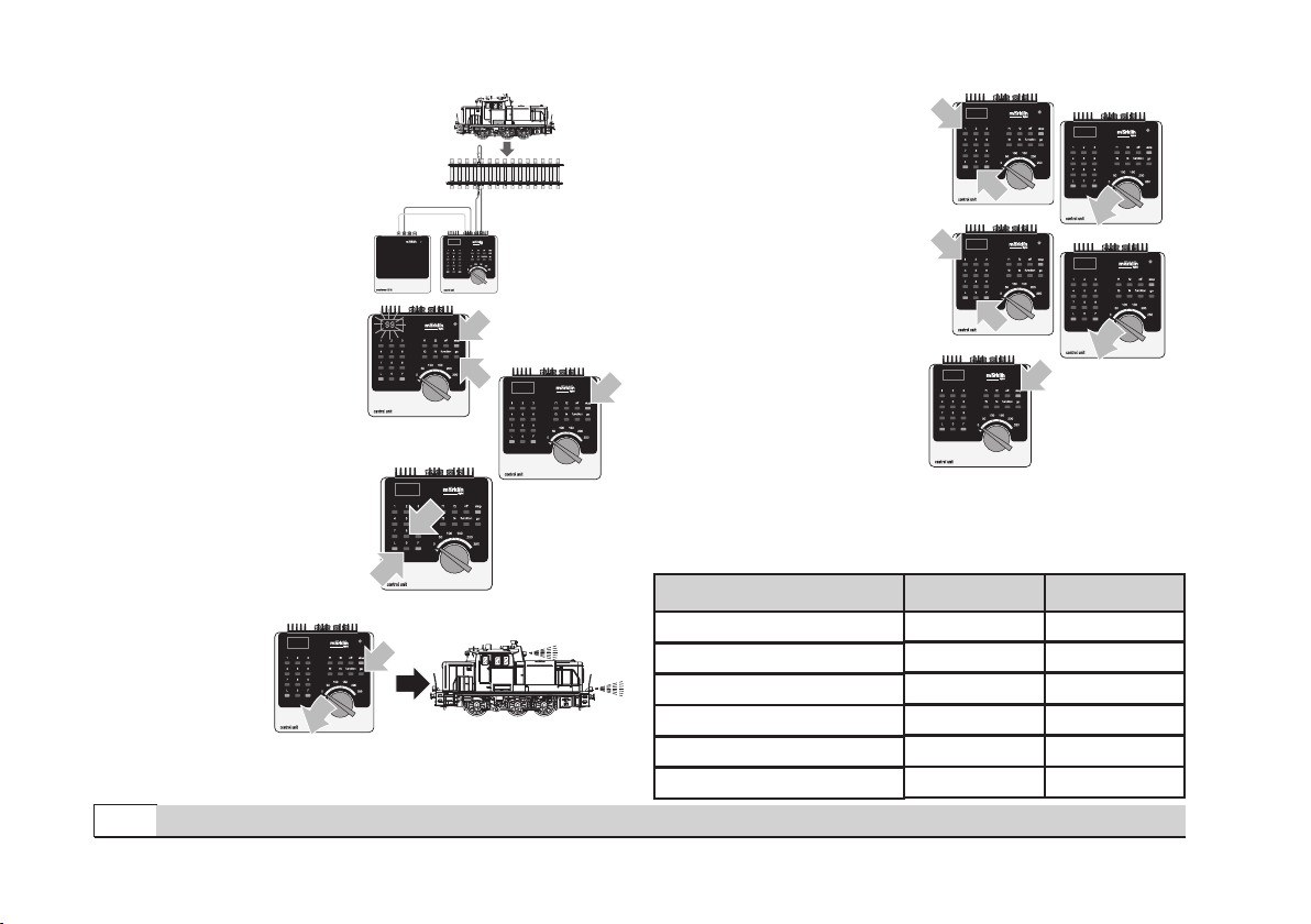
This locomotive has a built-in multi-train electronic circuit
and offers these features:
• Optional operation with DC power (max. ± 18 volts DC),
AC power (with Märklin 32 VA transformer), with Märklin
Delta (only with the 6607 Delta Station), Märklin Digital
(only with the Control Unit), or Märklin Systems (Mobile
Station, Central Station).
• The mode of operation is automatically recognized.
• 80 multi-train addresses (4 of them for the Delta System)
can be set. Address that set at the factory: 61 + 62.
• Adjustable acceleration (ABV).
• Adjustable Braking delay (ABV)
• Adjustable maximum speed.
• Setting the locomotive parameters electronically with the
Control Unit, Mobile Station or Central Station.
• Built-in sound effects circuit, can only be used in opera-
tion with the Control Unit or Märklin Systems. Additional
sound effects that can be controlled.
• The model is designed for operation on Märklin 1 Gauge
track. As the consumer you assume the risk for operating
on other makes of track.
• Minimum radius for operation: 600 mm / 23-2/3“.
• The model has a Telex coupler at both ends that can
be uncoupled with a switching command from Märklin
1- Gauge models with claw couplers, when you are in
digital/ systems operation. You may have operations pro-
blems if you use other makes of couplers.
• Except for the headlights, all of the functions are off in the
modes of operation for DC power, AC power, and Märklin
Delta.
Maintenance procedures that become necessary with
normal operation of the locomotive are described below.
Please see your authorized Märklin dealer for repairs or
spare parts.
No warranty or damage claims shall be accepted in those cases where parts
neither manufactured nor approved by Märklin have been installed in Märklin
products or where Märklin products have been converted in such a way that
the non-Märklin parts or the conversion were causal to the defects and / or
damage arising. The burden of presenting evidence and the burden of proof
thereof, that the installation of non-Märklin parts or the conversion in or of
Märklin products was not causal to the defects and / or damage arising, is
borne by the person and / or company responsible for the installation and /
or conversion, or by the customer.
Safety Warnings
•
This locomotive is to be used only with an operating
system designed
for it (Märklin 6646/6647 AC transformer,
Märklin Delta, Märklin Digital or Märklin Systems).
• This locomotive must never be supplied with power from
more than one transformer.
•
Pay close attention to the safety warnings in the instructions
for your operating system.

9
Betrieb • Operation • Fonctionnement • Exploitatie
Controllable Functions 6647 6021
STOP
mobile station
systems
60652 60212
Direction-dependent Headlights Always On 1) 61/ function + off2) Headlight Button Button by Symbol
Locomotive Operating Sounds - 61/f2 2) Button by Symbol Button by Symbol
Horn Sound Effect - 61/f3 2) Button by Symbol Button by Symbol
Telex Couplers -61/f4 2) Button by Symbol Button by Symbol
Switching Range (only ABV) -62/f1 2) Button by Symbol Button by Symbol
Sound Effect: Pneumatic -62/f2 2) Button by Symbol Button by Symbol
Noise when coupling -62/f3 2) Button by Symbol Button by Symbol
1) => Intensity dependent on the level of supply voltage.
2) => 61 = 1. address, 62 = 2. adress

10 Betrieb • Operation • Fonctionnement • Exploitatie
Setting Locomotive
Parameters with the
Control Unit
1. Requirement: Setup as
in diagram 1. Only the
locomotive to be changed
can be on the track.
2. Press the “Stop” and
“Go” at the same time
until “99” blinks in the
display.
3. Press the “Stop” button.
4. Enter the address „80“.
5. Hold the speed cont-
rol knob in the reverse
direction position con-
stantly. Press the
“Go” button while
you do this. The
headlight on the
locomotive will
blink. If no, repeat
starting at Step 2.
6. Enter the register number
for the parameter to be
changed (=> List 1).
7. Activate the direction
reversal.
8. Enter new value
(=> List 1).
9. Activate the direction
reversal.
10. End the procedure by
pressing the “Stop”
button. Now press the
“Go” button.
Important: On the 1st address
is changed, when changing the
locomotive’s address. The 2nd
address is always the following
address.
=> Maximum value for the 1st
address is 79.
Diagram 1
1
1
99
1
2
80
1
80
1
2
1
01
01
1
1
2
10
10
1
List 1: parameter
Register Number
Value
01 01 - 79
Address
03 01 - 63
Acceleration delay
04 01 - 63
Braking delay
05 01 - 63
Maximum speed
08 08
Reset to series values
63 01 - 63
Volume

11
Betrieb • Operation • Fonctionnement • Exploitatie
Changing Locomotive Parameters with the
Mobile Station
1. Select the locomotive from the locomotive list.
2. Change to the submenu “EDIT LOC”.
3. Change to the submenu “ADDRESS”, “VMAX”, “VOL“,
“ACC” or “DEC”.
4. Enter the new value and accept it into the system.
Note the references and information in the instructions for
the Mobile Station.
Changing Locomotive Parameters with the
Central Station.
Note the references and
information in the instructions
for
the Central Station. The 54323 locomotive can be found in
the database for the Central Station.
Note: When you are reprogramming the locomotive para-
meters, no other locomotive or other units can be receiving
power from the Central Station.

12 Betrieb • Operation • Fonctionnement • Exploitatie
Fonctionnement
Cette locomotive possède un équipement électronique
pour conduite multitrain:
• Au choix, exploitation conventionnelle avec courant
continu (max ± 18 volts =), courant alternatif (Transformer
32 VA), exploitation avec Märklin Delta (uniquement Delta
Station 6607), Märklin Digital (uniquement Control Unit)
ou Märklin Systems (Mobile Station ou Central Station).
Une exploitation avec d’autres systèmes d’exploitation
(courant à largeur d’impulsion variable, Central Control 1,
etc.) n’est pas possible.
• Le mode d’exploitation est automatiquement détecté.
• 80 adresses pour conduite multitrain (dont 4 pour le
système Delta) sont disponibles. Adresse réglée en usine:
61 + 62.
• Temporisation d’accélération réglable (ABV).
• Temporisation de freinage réglable (ABV).
• Vitesse maximale réglable.
• Réglage des paramètres de la loco électroniquement à
l’aide de la Control Unit, de la Mobile Station ou de la
Central Station.
• Bruiteur électronique intégré, utilisable uniquement lors
d’exploitation avec la Control Unit ou Märklin Systems.
Bruitages complémentaires commutables.
• Le modèle réduit est conçu pour rouler sur des voies
Märklin 1. Le faire rouler sur des voies d’autres systèmes
comporte des risques.
• Rayon minimal d’inscription en courbe: 600 mm.
• Le modèle est équipé d’attelages Telex grâce auxquels il
est possible, en exploitation digital/ systems, de dételer à
distance les modèles Märklin 1 dotés d’attelages à griffe.
En cas d’utilisation d’un système provenant d’un autre
fabricant, des problèmes sont susceptibles de survenir.
• A l’exception des feux de signalisation, les fonctions sont
désactivées en mode d’exploitation courant continu,
courant alternatif et Märklin Delta.
Les travaux d‘entretien occasionnels à effectuer en
exploitation normale sont décrits plus loin. Pour toute répa-
ration ou remplacement de pièces, adressez-vous à votre
détaillant-spécialiste Märklin.
Tout recours à une garantie commerciale ou contractuelle ou à une demande de
dommages-intérêt est exclu si des pièces non autorisées par Märklin sont inté-
grées dans les produits Märklin et / ou si les produits Märklin sont transformés
et que les pièces d’autres fabricants montées ou la transformation constituent
la cause des défauts et / ou dommages apparus. C’est à la personne et / ou la
société responsable du montage / de la transformation ou au client qu’incombe
la charge de prouver que le montage des pièces d’autres fabricants sur des
produits Märklin ou la transformation des produits Märklin n’est pas à l’origine
des défauts et ou dommages apparus.
Remarques importantes sur la sécurité
• La locomotive ne peut être mise en service qu’avec un
système d’exploitation adéquat (Märklin courant alterna-
tif -transformateur 6647, Märklin Delta, Märklin Digital ou
Märklin Systems).
• La locomotive ne peut être alimentée en courant que par
une seule source de courant.
• Veuillez impérativement respecter les remarques sur la
sécurité décrites dans le mode d’emploi en ce qui concerne
le système d’exploitation.

13
Betrieb • Operation • Fonctionnement • Exploitatie
Fonctions commutables 6647 6021
STOP
mobile station
systems
60652 60212
Eclairage des feux de signalisation Activé en
permanence 1) 61/ function + off2) Touche éclairage Touche à côté symbole
Bruitage locomotive - 61/f2 2) Touche à côté symbole Touche à côté symbole
Bruitage klaxon - 61/f3 2) Touche à côté symbole Touche à côté symbole
Attelage Telex -61/f4 2) Touche à côté symbole Touche à côté symbole
Mode manoeuvre (seulement ABV) -62/f1 2) Touche à côté symbole Touche à côté symbole
Bruitage de pneumatique -62/f2 2) Touche à côté symbole Touche à côté symbole
Bruit lors de l‘attelage -62/f3 2) Touche à côté symbole Touche à côté symbole
1) => L’intensité est fonction de la tension d’alimentation.
2) => 61 = 1e adresse, 62 = 2e adresse

14 Betrieb • Operation • Fonctionnement • Exploitatie
Réglage des pa-
ramètres de la loco
avec la Control Unit
1. Condition: Montage com-
me sur illustration 1. Seule
la loco à modifier peut se
trouver sur la voie.
2. Pressez simultanément
les touches „Stop“ et
„Go“ jusqu’à ce que le
nombre „99“ clignote sur
l’écran.
3. Pressez la touche „Stop“.
4. Introduisez l’adresse
„80“.
5. Tout en procédant à
l’inversion sur
le régulateur,
pressez la touche
„Go“. Les feux
clignotent sur la
loco. Si ce n’est
pas le cas, répé-
tez l’étape 2.
6. Introduisez le numéro de
registre pour le paramètre
à modifier (=> liste 1).
7. Exécutez l’inversion du
sens de marche.
8. Introduisez la nouvelle
valeur (=> liste 1).
9. Exécutez l’inversion du
sens de marche.
10. Terminez le processus
en pressant la touche
„Stop“. Ensuite, pressez
la touche „Go“.
Remarque: C’est toujours la
1e adresse qui est modifiée.
La 2e adresse est toujours
l’adresse suivante.
=> 1e adresse maximale: 79.
Illustration 1
1
1
99
1
2
80
1
80
1
2
1
01
01
1
1
2
10
10
1
Liste 1: Paramètre Numéro du
registre Valeur
01 01 - 79
Addresse
03 01 - 63
Temporisation d‘accélération
04 01 - 63
Temporisation de freinage
05 01 - 63
Vitesse maximale
08 08
Remettre aux valeurs de série
63 01 - 63
Volume haut-parleur

15
Betrieb • Operation • Fonctionnement • Exploitatie
Modification des paramètres de la locomotive
à l‘aide de la Mobile Station
1. Sélectionnez la loco dans la liste.
2. Allez au sous-menu „MODIF LOC“.
3. Allez au sous-menu „ADRESSE“, „VMAX“, „VOL“, „ACC“
ou „DEC“.
4. Entrez la nouvelle valeur et acceptez.
Tenir compte des remarques faites dans les instructions
de la Mobile Station.
Modification des paramètres de la locomotive
à l‘aide de la Central Station.
Tenir compte des remarques faites dans les instructions
de la Central Station. La locomotive 54323 se trouve dans
la banque de données de la Central Station.
Remarque : lors du changement de programmation des
paramètres de la locomotive, aucune autre locomotive ou
aucun autre consommateur ne doit être alimenté par la
Central Station.

16 Betrieb • Operation • Fonctionnement • Exploitatie
Werking
Deze loc met ingebouwde digitaalelektronica biedt u:
• Naar keuze conventioneel bedrijf (wisselstroom met de
Transformer 32 VA of gelijkstroom [max +/– 18 Volt=] ),
bedrijf met Märklin Delta (alleen het Delta Station 6607),
Märklin Digital (Control Unit) of het Märklin Systems (Mo-
bile Station of Central Station). Het bedrijf met rijregelaars
van andere systemen (bijv. impulsbreedte sturing, gebruik
van de Central-Control 1 (6030) of een dergelijk systeem)
is niet mogelijk.
• Het bedrijfssysteem wordt automatisch herkend.
•
80 meertreinen-adressen (4 daarvan voor het Delta-sys-
teem) instelbaar. Ingesteld adres vanaf de fabriek: 61 + 62.
•
Instelbare optrekvertraging.
• Instelbare afremvertraging.
• Instelbare maximumsnelheid.
• Elektronische instelling van de locomotiefparameters via
de Control Unit, Mobile Station of Central Station.
• Ingebouwde geluidselektronica, alleen bruikbaar in het
bedrijf met de Control Unit of Märklin Systems. Extra
schakelbare geluiden.
• Het model is ontwikkeld voor het gebruik op het Märklin
Spoor 1 railsysteem. Het gebruik op een ander railsys-
teem geschied op eigen risico.
• Berijdbare minimumradius: 600 mm.
• Het model beschikt zowel voor als achter over een
telexkoppeling. Hiermee kunnen in digitaal/ systems be-
drijf Märklin 1- modellen voorzien van klauwkoppellingen
met een schakelcommando afgekoppeld worden. Bij het
gebruik van koppelingssystemen van andere fabrikanten
zijn storingen niet uit te sluiten.
De in het normale bedrijf voorkomende onderhouds-
werkzaamheden zijn verderop beschreven. Voor reparatie of
onderdelen kunt u zich tot uw Märklin winkelier wenden.
Elke aanspraak op garantie en schadevergoeding is uitgesloten, wanneer
in Märklin-producten niet door Märklin vrijgegeven vreemde onderdelen
ingebouwd en / of Märklin-producten omgebouwd worden en de ingebou-
wde vreemde onderdelen resp. de ombouw oorzaak van nadien opgetreden
defecten en / of schade was. De aantoonplicht en de bewijslijst daaromtrent,
dat de inbouw van vreemde onderdelen in Märklin-producten of de ombouw
van Märklin-producten niet de oorzaak van opgetreden defecten en / of
schade is geweest, berust bij de voor de inbouw en/of ombouw verantwoor-
delijke persoon en / of firma danwel bij de klant.
Veiligheidsvoorschriften
• De loc mag alleen met een daarvoor bestemd bedrjfssys-
teem (Märklin wisselstroom transformator 6647, Mär-
klin Delta, Märklin digitaal of Märklin Systems) gebruikt
worden.
• De loc mag niet vanuit meer dan één stroomvoorziening-
gelijktijdig gevoed worden.
• Lees ook aandachtig de veiligheidsvoorschriften in de
gebruiksaanwijzing van uw bedrijfssysteem.

17
Betrieb • Operation • Fonctionnement • Exploitatie
Schakelbare functies 6647 6021
STOP
mobile station
systems
60652 60212
Frontverlichting rijrichtingafhankelijk Continu aan 1) 61/ function + off2) Verlichtingstoets Toets bij het symbool
Bedrijfsgeluid - 61/f2 2) Toets bij het symbool Toets bij het symbool
Geluid van signaalhoorn - 61/f3 2) Toets bij het symbool Toets bij het symbool
Telexkoppeling -61/f4 2) Toets bij het symbool Toets bij het symbool
Rangeerstand (alleen ABV) -62/f1 2) Toets bij het symbool Toets bij het symbool
Geluid perslucht -62/f2 2) Toets bij het symbool Toets bij het symbool
Geluid bij het ankoppelen -62/f3 2) Toets bij het symbool Toets bij het symbool
1) => Intensiteit afhankelijk van de hoogte van de voedingsspanning.
2) => 61 = eerste adres, 62 = tweede adres

18 Betrieb • Operation • Fonctionnement • Exploitatie
Locparameters in-
stellen met de Cont-
rol Unit
1. Voorwaarde: opbouw
zoals tekening 1. Alleen
de loc die gewijzigd moet
worden op de rails.
2. ”Stop”- en ”Go”-toets
gelijktijdig indrukken tot
”99” in het display oplicht.
3. ”Stop”-toets indrukken.
4. Adres „80“ invoeren.
5. Omschakelcommando
met de rijregelaar continu
bedienen. Daarbij
de ”Go”-toets
indrukken. De
verlichting van de
loc knippert. Als
dit niet het geval
is, vanaf stap 2 herhalen.
6. Het registernummer van
de te wijzigen parameter
invoeren (=> lijst 1).
7. Rijrichtingomschakeling
bedienen.
8. Nieuwe waarde invoeren
(=> lijst 1).
9. Rijrichtingomschakeling
bedienen.
10. Programmering beëin-
digen door het indrukken
van de ”Stop”-toets.
Aansluitend de ”Go”-toets
indrukken.
Opmerking: het eerste adres kan
altijd worden gewijzigd. Het tweede
adres is altijd het daarop volgende
adres.
=> Het eerst adres is maximaal
adres 79.
Tekening 1
1
1
99
1
2
80
1
80
1
2
1
01
01
1
1
2
10
10
1
Liste 1: Parameter
Registernummer
01 01 - 79
Adres
03 01 - 63
Optrekvertraging
04 01 - 63
Afremvertraging
05 01 - 63
Maximumsnelheid
08 08
Terugzetten naar serie-instellingen
63 01 - 63
Volume
Waarde

19
Betrieb • Operation • Fonctionnement • Exploitatie
Locparameter met het Mobile Station
wijzigen
1. Loc uit de loclijst kiezen.
2. Ga naar het nevenmenu ”WYZIG LOC”.
3. Ga naar het nevenmenu ”ADRES”, ”MAX.SNELH.”,
„VOL“, ”OPTREKKEN” of ”AFREMMEN”.
4. Nieuwe waarde invoeren en overnemen.
Neem ook de aanwijzingen in de gebruiksaanwijzing van
het Mobile Station in acht.
Locparameter met het Central Station
wijzigen.
Neem de aanwijzingen in de gebruiksaanwijzing van
het Central Station in acht. De loc 54323 is aanwezig in de
databank van het Central Station.
Opmerking: bij het omprogrammeren van de locparame-
ter mogen geen andere locomotieven of andere verbruikers
door het Central Station van stroom worden voorzien.

20 Betrieb auf der Anlage • Operation on a layout • Exploitation sur réseau • Bedrijf op een modelbaan
Anschluss der Gleisanlage
Um Spannungsverluste auf
der Anlage zu vermeiden ist
immer auf gutes Zusammen-
passen der Schienenverbin-
dungslaschen zu achten.
Alle 2 bis 3 m ist eine neue
Stromeinspeisung über die
Anschlussklemmen 5654 emp-
fehlenswert.
Befahren von Steigungen
Im Gegensatz zum Vorbild
können mit einer Modellbahn
auch größere Steigungen
befahren werden. Im Normalfall
sollte eine Steigung bei maxi-
mal 3 Prozent liegen. Im Ex-
tremfall sind bei entsprechend
eingeschränkter Zugleistung
maximal 5 Prozent möglich.
Der Anfang und das Ende der
Steigung sind auf jeden Fall
auszurunden.
Der Unterschied in der
Steigung zwischen zwei
mindestens 300 mm langen
Gleisstücken darf maximal 1
bis 1,5 Prozent betragen.
Connections between
the track layout and the
transformer
Rail joiners must fit well on
the rails of the track to which
they are joined to avoid voltage
drop on the layout. We recom-
mend that you install feeder
wires every 2 to 3 meters (7 to
10 feet) using the 5654 feeder
clips.
Operating the locomotive
on grades
In contrast to the prototype
a
locomotive on a model railroad
can operate up steeper grades.
As a general rule a grade
should be no steeper than 3%.
In extreme situations a maxi-
mum grade of 5% is permis-
sible, keeping in mind that the
locomotive’s tractive effort will
be less. The beginning and the
end of the grade must always
work gradually up to maxi-
mum grade for the route. The
maximum allowable difference
in grade between two track
sections, each with a minimum
length of 300 mm (11-3/4“) is 1
to 1.5 percent.
Connexion des voies
ferrées
Pour éviter des pertes de
potentiel sur l’installation, il faut
veiller à ce que les éclisses de
liaison des rails soient toujours
parfaitement adaptées. Une
nouvelle alimentation élec-
trique est conseillée tous les
2 à 3 m au moyen des griffes
d’alimentation 5654.
Franchissement des côtes
Contrairement à l’original,
la maquette est également en
mesure de franchir des côtes
assez importantes. En temps
normal, une côte devrait étre
de l’ordre de 3% maximum.
A l’extrême limite, 5% sont
envisageables avec une
puissance du train réduite en
consequence. Le début et la fin
de la côte doivent en tous cas
étre arrondis.
La différence de pente
entre deux éléments de voie
d’au moins 300 mm de lon-
gueur doit étre de 1 à 1,5%
maximum.
Aansluiting van de sporen
Om spanningsverlies op
de modelbaan te voorkomen
moeten de raillassen altijd goed
op elkaar aansluiten. Om de 2 à
3 meter moet de voeding opni-
euw op de rails gezet worden.
Daarbij zijn de aansluitklemmen
5654 aan te raden.
Berijden van hellingen
In tegenstelling tot het grote
voorbeeld kunnen met een
modelbaan ook grotere hellin-
gen bereden worden. Normaal
moet een helling maximaal
3 procent zijn.
In extreme
gevallen is maximaal 5 procent
mogelijk, maar
dan moet reke-
ning gehouden worden met een
evenredig verlies aan vermo-
gen. Het begin en het einde
van de helling moeten altijd
gerond worden.
Het verschil in de helling
tussen twee tenminste 300 mm
lange railstukken mag maxi-
maal 1 à 1,5 procent bedragen.
This manual suits for next models
1
Table of contents
Languages:
Other marklin Model Train manuals

marklin
marklin 55247 User manual

marklin
marklin 55333 User manual

marklin
marklin 55804 User manual

marklin
marklin 55717 User manual

marklin
marklin 58016 User manual

marklin
marklin 58013 User manual

marklin
marklin 55918 User manual

marklin
marklin 58081 User manual

marklin
marklin 55185 User manual

marklin
marklin 55385 User manual

marklin
marklin 55383 User manual

marklin
marklin 55424 User manual

marklin
marklin 55381 User manual

marklin
marklin 55414 User manual

marklin
marklin 55334 User manual

marklin
marklin 55963 User manual

marklin
marklin 55184 User manual

marklin
marklin 55384 User manual

marklin
marklin 55182 User manual

marklin
marklin 55183 User manual