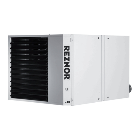
Reznor RHC21 4000 Guide

MANUAL PART NO. D301334 ISS 0
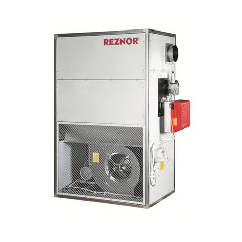
RHC21 4000
GAS FIRED AIR HEATER MODULE
Please read this document carefully before commencing installation, commissioning and/or servicing.
Leave it with the end user/site agent to be placed in their premises technical file after installation.
WARNING
Improper installation, adjustment, alteration, service or maintenance can cause property damage, injury or death.
All work must be carried out by appropriately qualified persons.
The manufacturer does not take any responsibility in the event of non-observance of the regulations concerning the connection of the apparatus causing a
dangerous operation possibly resulting in damage to the apparatus and/or environment in which the unit is installed.
EU)2016/426(GAR),2009/125/EC(ErP), 2014/35/EU(LVD),and2014/30/EU(EMC)
Regulations and Directives.
The following harmonised standards have been applied:
EN 17082, EN 60335-1, EN 60335-2-102, EN 55014-1, and EN 55014-2
INSTALLATION / COMMISSIONING / SERVICING
ErP
2021
ErP Lot 21
Seasonal Efficiency
and NOx compliant

Contents
Important Notice to Installers ............................................ 4
Health and Safety ............................................................. 5
1. Introduction ................................................................. 6
1.1 Basic information........................................................ 6
1.2 Warranty .................................................................... 7
1.3 Definitions .................................................................. 7
2. Technical data ............................................................... 8
3. Dimensions................................................................... 10
Figure 1 side view ............................................................. 10
Figure 2 top view.............................................................. 11
Figure 3 front view............................................................ 12
4. Installation ................................................................... 14
4.1 General requirements ................................................. 14
4.2 Unpacking and preparation......................................... 14
4.3 Heater location ........................................................... 14
4.4 Minimum airflow requirement..................................... 14
4.5 Maximum airflow condition ........................................ 14
4.6 Compartment dimensions........................................... 16
4.7 Combustion air supply and flue systems...................... 17
4.8 Type B Appliances ....................................................... 18
4.9 Type C Appliances....................................................... 18
4.10 Gas supply................................................................ 19
4.11 Electrical supply ........................................................ 20
4.12 Electrical Isolator....................................................... 21
4.13 Room space / duct sensor siting ................................ 21
4.14 Wiring diagrams ....................................................... 21
4.15 Condensate collection and disposal........................... 21
5. Commissioning and testing........................................... 22
5.1 Electrical check ........................................................... 22
5.2 Gas connection........................................................... 22
5.3 Pre start checks........................................................... 22
5.4 Start up ...................................................................... 23
5.5 Air / gas ratio controls................................................. 23
5.6 Modular heaters ......................................................... 23
5.7 Gas valve adjustments................................................. 23
5.8 Gas conversion ........................................................... 24
5.9 Commissioning........................................................... 26
5.10 Commissioning - hand over ...................................... 28
5.11 Operation ................................................................. 28
5.12 To turn the air heater OFF for short periods............... 29
5.13 To turn the air heater OFF for long periods................ 29
6 Servicing and maintenance ............................................ 31
RHC21 4024-05 component layout.............................. 31
RHC 4036-08, 4050-06, 4060-07, 4075-09 and
4100-12 component layout ......................................... 33
RHC21 4125M15 and 4150M18 component layout..... 35
6.1 Service procedure ....................................................... 36
6.2 Heat exchanger maintenance...................................... 36
7 Removal and replacement of parts................................. 37
7.1 Replacement of gas valve............................................ 37
7.2 Venturi cleaning and replacement ............................... 38
7.3 Combustion fan cleaning and replacement ................. 39
7.4 Burner cleaning and replacement................................ 40
7.5 Burner chamber / tube insulation check
and replacement............................................................... 40
7.6 Cleaning and replacement of burner probes ............... 42
7.7 Replacement of LC3 safety thermostats ...................... 43
7.8 Replacement of ignition controller .............................. 44
7.9 Replacement of ignition transformer ........................... 44
7.10 Replacement of lockout circuit board ........................ 44
7.11 Flue and combustion air............................................ 44
7.12 Unit operation .......................................................... 44
8. Fault finding ................................................................. 45
9 Parts listing .................................................................... 47
10 User operating instructions .......................................... 48
10.1 Checks before lighting the air heater ........................ 48
10.2 Lighting the air heater............................................... 48
10.3 To shut down the air heater ...................................... 48
10.4 Overview of operation .............................................. 48
10.5 Maintenance............................................................. 48
10.6 Important note ......................................................... 49
11 ErP tables..................................................................... 50
ErP table - G20 ............................................................ 50
ErP table - G25 ............................................................ 51
Erp table - G25.3 ......................................................... 52
Handover document commissioning details....................... 53

Nortek Global HVAC (UK) Ltd
Fens Pool Avenue, Brierley Hill, West Midlands, DY5 1QA, England
Tel: +44(0)1384 489 700 Fax: +44(0)1384 489 707
_____________________________________________________________________________________
EC Declaration of Conformity
_____________________________________________________________________________________
Product: Power-vented gas-fired air heaters
Model Type(s): RHC21 4000 Series Models (4024-05 / 4036-08 / 4050-06 / 4060-
07 / 4075-09 / 4100-12 / 4125M15 / 4150M18)
This declaration is issued under the sole responsibility of the manufacturer. The object of
the declaration is to detail that the product listed above is in conformity with the following
applicable standards and legislation:
Number Description
2006/42/EC Machinery Directive
2016/426 (EU) Gas Appliance Regulations (GAR)
2009/125/EC Eco-Design Directive (ErP)
2014/35/EU Low Voltage Directive (LVD)
2014/30/EU Electromagnetic Compatibility Directive (EMC)
Applicable Standards Applied
EN 17082:2019 Domestic and non-domestic gas-fired forced convection
air heaters for space heating not exceeding a net input of
300kW
IEC 60335-1:2020 Household and similar electrical appliances - Safety - Part
1: General requirements.
EN 60335-2-102:2006 Household and similar electrical appliances - safety.
Particular requirements for gas, oil and solid-fuel burning
appliances having electrical connections
EN IEC 55014-1:2021 Electromagnetic compatibility - Requirements for
household appliances, electric tools and similar
apparatus. Part 1: Emission
EN IEC 55014-2:2021 Electromagnetic compatibility. Requirements for
household appliances, electric tools and similar
apparatus. Immunity.
Controls Applied
BS EN ISO 9001:2015 (LRQA Registered Company (N° LRQ 0870105/A)
Technical documentation for the product is available from this address.
Signed on behalf of Nortek Global HVAC (UK) Ltd
Gavin Horton
Quality Lead for Nortek Global HVAC (UK) Ltd 10/06/2021

Page No 4 of 56 Reznor, RHC21 4000 Installation EN May 2021 D301334 Issue 0
In instances where copper pipework is to
be used for all or part of a gas pipework
installation, including short length final
connections then we advise that installers
consult with the gas supplier or provider and
satisfy themselves what additional precautions
may be necessary.
Improper installation, adjustment,
alteration, service, or maintenance
can cause property damage,
injury, or death. Read the
installation, operation, and
maintenance instructions
thoroughly before installing or
servicing this equipment.
Gas-fired appliances are not designed for
use in hazardous atmospheres containing
flammable vapours or combustible dust,
in atmospheres containing chlorinated or
halogenated hydrocarbons or in applications
with airborne silicone substances.
Any reference made to Laws, Standards,
Directives, Codes of Practice or other
recommendations governing the application
and installation of heating appliances and
which may be referred to in Brochures,
Specifications, Quotations, and Installation,
Operation and Maintenance manuals is done
so for information and guidance purposes only
and should only be considered valid at the
time of the publication.
The manufacturer cannot be held responsible
from any matters arising from the revision
to or introduction of new Laws, Standards,
Directives, Codes of Practice or other
recommendations.
The temperature in the controls section of the
unit must never be less than -10°C otherwise
damage could occur to the sealing elements of
the gas valve and to the electrical components.
The electrical isolator should only be used in an
emergency and should not be used for closing
down the main burner, as it switches off the
fan prematurely and may damage the heat
exchanger, invalidating the warranty.
Important notice to
installers
Before installation, carefully read these
instructions and follow the processes explained
by the manufacturer. These instructions are
only valid for appliances designed to operate in
Europe. If the country code and gas category
on the appliance data label does not match
the country of installation or the country codes
and gas categories as shown in this instruction
manual, it will be necessary to contact the
distributor or manufacturer to provide the
necessary information for the modification of
the appliance to the conditions of use for the
country of installation.
Installing, commissioning, testing,
programming and maintenance of these
products must only be carried out by suitably
qualified and trained technicians and in full
compliance with all applicable regulations and
current best practices.
Check if the appliance as described on the
packaging label is in accordance with the
correct type and model as specified on the
data plate and complies with your customer
order.
Check that the temperature ranges given
and those of the location match. The
appliance must be powered with a voltage
corresponding to the value shown on the
rating plate.
These units must be installed in accordance
with the rules in force and local regulations /
legislation as appropriate plus all local building
codes. Installers should satisfy themselves that
the gas pipework installation is carried out in
accordance with all current legislation, Codes
of Practice and recommendations.
Additionally it may be necessary to protect
the gas valves which form part of the heater
or burner assembly from potential pipe
contamination particularly, but not exclusively,
where copper gas pipework is used.
Reznor, RHC21 4000 Installation EN May 2021 D301334 Issue 0 Page No 5 of 56
Health and safety
Due consideration should be taken for
workplace safety, risk assessments and waste
disposal.
Any modification of the product may be
hazardous and the manufacturer is not liable
for any damage or injury caused by improper
use.
Do not use this appliance if any part has been
immersed in water. Immediately call a qualified
service technician to inspect the appliance
and replace any gas control that has been
immersed in water.
This appliance is not intended for use by
persons (including children) with reduced
sensory or mental capabilities or lack of
experience and knowledge, unless they
have been given supervision or instruction
concerning use of the appliance by a person
responsible for their safety. Children should
be supervised to ensure that they do not play
with the appliance.
Should overheating occur or the gas supply
fails to shut off, shut off the manual gas
valve to the appliance before shutting off the
electrical supply.
Gas-fired appliances are not designed for
use in hazardous atmospheres containing
flammable vapours or combustible dust,
in atmospheres containing chlorinated or
halogenated hydrocarbons or in appliances
with airborne silicone substances.
The manual should be kept in a safe place for
future reference.
For your safety, if you smell gas:
• Do not try to light any
appliance
• Do not touch any electrical
switch, do not use any phone
in your building
• Evacuate all personnel
• Contact your gas supplier
immediately
Do not store or use petrol or other
flammable vapours and liquids in
the vicinity of the appliance.
Improper installation, adjustment,
alteration, service or maintenance
can cause property damage, injury
or death.
Read the installation, operation
and maintenance instructions
thoroughly before installing or
servicing this equipment.
Installation, assembly,
commissioning, service and
maintenance procedures must
be carried out only by suitably
competent qualified persons.
Unauthorised modifications to
the appliance, or departure from
the manufacturer’s guidance
on intended use, or installation
contrary to the manufacturer’s
recommendations may constitute
a hazard.
Use only factory authorised parts
and spares when replacement is
required.
In case of persistent problems,
contact your distributor.

Page No 6 of 56 Reznor, RHC21 4000 Installation EN May 2021 D301334 Issue 0
1. Introduction
Isolate any electrical supply to
the heater and controller before
proceeding.
1.1 Basic information
The instructions in this manual apply to the
RHC21 4000 gas-fired air heating modules
installed at an operational ambient temperature
between -15°C and +45°C.
The appliances must be installed in accordance
with the rules in force. Before installation, check
that the local distribution conditions,nature
of gas and pressure and adjustment of the
appliance are compatible.
A permanent electricity supply of 230 volts, 50
hertz, single phase is required.
RHC21 4000 air heater modules are suitable for
use in internal and external air handling units
(when installed internally where the height
above floor level is greater than 1.8 meters
measured to the underside of the appliance they
may be used as a garage air heater).
Model RHC21 4000 air heater modules may
be installed as a Type C room sealed heater
requiring both a combustion air inlet pipe and a
flue pipe (Type C13, C33 or C53 only) or as a Type
B forced draught heater where the combustion
air is taken from the room space the heater is
installed in and which requires only a flue pipe
exhausting to outdoors (Type B23 or B53 only).
All products of combustion must be flued to
outdoor atmosphere.
All models and sizes are available for use
with natural gas with operating temperatures
between 15°C and 40°C.
These instructions are only valid for appliances
designed to operate in Europe. If the country
code and gas category on the appliance
data label does not match the country of
installation or the country codes and gas
categories as shown in this instruction
manual, it will be necessary to contact the
distributor or manufacturer to provide the
necessary information for the modification of
the appliance to the conditions of use for the
country of installation.
Check that the local distribution conditions of
electricity supply, type of gas and pressure of
the appliance are compatible.
The total installation should be installed in
accordance with the rules in force, relevant
National Standards, local regulations,and Codes
of Practice.
When the external control calls for heat, an
electronic control begins the ignition sequence
to provide for a safe start.
Under normal conditions the fan motor runs
constantly and after a call for heat it switches
the heater on through a room or duct stat.
However,in some applications, about 30 seconds
after the call for heat, the fan control relay will
activate the fan motor of the air handler.
The electronic control will supervise the flame
during the entire heating cycle to ensure safe
operation. When the required room temperature
is reached, the main burner will shut down
leaving the fan running to cool down the heat
exchanger. After approximately 45 seconds, the
fan delay relay will turn off the fan (if wired).
All models may only be used when installed
within a closed compartment, e.g. an air
handling unit or using the optional vestibule.
For dimensions refer to figures 1,2 & 3
following. All dimensions are in mm
(25.4mm= 1inch)
Only recognised air handling unit
manufacturers are authorised to
build in the heater module. Please
contact your distributor.
Any other application is forbidden
and dangerous. Failure to comply
can result in severe personal injury,
death and/or property damage.
Note: manufacturer warranties do
not apply in such circumstances.

Reznor, RHC21 4000 Installation EN May 2021 D301334 Issue 0 Page No 7 of 56
1.2 Warranty
This equipment comes as standard with a
manufacturers two year warranty (2 years parts,
1 year labour) unless agreed otherwise at the
time of order. The warranty is void if:-
• Model RHC21 4000 heaters are installed in
atmospheres containing flammable vapours
or atmospheres containing chlorinated or
halogenated hydrocarbons or atmospheres
containing any silicone, aluminium oxide,etc.
that adheres to spark ignition flame sensing
probes.
• The installation is not in accordance with
these instructions.
• The maximum air flow through the heat
exchanger tubes is not respected (see section
3.5).
• The required minimum air delivery is not
respected (see table 7).
• The duct dimensions do not comply with the
prescribed dimensions (see table 8)
• The inlet temperature (measured at the heat
exchanger inlet) is lower than the value
stated on the chart (see fig.5: dew point
occurrence chart).
1.3 Definitions
Module:
The gas-fired heating module.
Constructor:
The undertaking, which builds a module into
another casing. e.g. an air handling unit.
Appliance:
The end product of the constructor
Compartment:
The section of an appliance into which the
module is installed
B23 / B53 Appliance:
An appliance where the air for combustion
is taken from within the area where the gas
burner is operated. A flue pipe is required
exhausting to outdoors.
C13 / C33 / C53 Appliance:
An appliance where the air for combustion
is taken from outside the area where the
gas burner is operated (room sealed). Both a
combustion air inlet pipe and a flue pipe are
required.
Dew point:
The condition, when the temperature is such
that the water vapour in the combustion
products condenses out.
Dimensions:
All dimensions are in mm (25.4mm= 1 inch)

Page No 8 of 56 Reznor, RHC21 4000 Installation EN May 2021 D301334 Issue 0
2 Technical Data
Model RHC21 4024-05 4036-08 4050-06 4060-07 4075-09 4100-12 4125M15 4150M18
Combustion air & flue type Indoor B23 / B53 / C13 / C33 / C53
Combustion air & flue type External Rooftop
Heat Input High Fire (Hs) 1kW 29.30 44.00 61.50 77.60 91.50 120.00 153.00 183.00
Heat Input Low Fire (Hs) 1kW 8.79 13.20 18.60 22.38 27.45 37.00 45.20 49.08
Heat Input High Fire (Hi) 2kW 26.40 39.64 55.41 69.91 82.43 108.11 137.84 164.86
Heat Input Low Fire (Hi) 2kW 7.92 11.89 16.76 20.16 24.73 33.33 40.72 44.22
Heat Output H2 High Fire 4kW 24.17 36.19 51.20 64.74 76.04 99.61 125.43 151.25
Heat Output H2 Low Fire 4kW 7.77 11.69 16.49 19.75 24.33 32.81 40.04 43.55
Gas Consumption High Fire
(Hs) G20 3m³/h 2.79 4.19 5.86 7.39 8.71 11.43 14.57 17.42
Gas Consumption Low Fire
(Hs) G20 3 m³/h 0.84 1.26 1.77 2.13 2.61 3.52 4.30 4.67
Gas Consumption High Fire
(Hs) G25 3m³/h 3.24 4.87 6.81 8.59 10.13 13.29 16.94 20.26
Gas Consumption Low Fire
(Hs) G25 3m³/h 0.97 1.46 2.06 2.48 3.04 4.10 5.00 5.43
Gas Consumption High Fire
(Hs) G25.3 3m³/h 3.17 4.77 6.66 8.41 9.91 13.00 16.58 19.83
Gas Consumption Low Fire
(Hs) G25.3 3m³/h 0.95 1.43 2.02 2.43 2.97 4.01 4.90 5.32
Gas Service Connection Inches BSP ½" ¾" ¾" ¾" ¾" ¾" 1¼" 1¼"
Flue & Combustion Air
Connection Collars (Indoor) Ø mm 100 130 130 130 130 130 130 130
Condensation Connection /
Outlet Ø mm 22 OD
Minimum V1 Airflow at 15°C
with Heat Output H1 6
m³/h N/A N/A 3900 4700 5700 7500 N/A N/A
kW N/A N/A 50.0 60.0 73.8 96.6 N/A N/A
Temperature Rise at V1 Airflow K N/A N/A N/A N/A
Minimum V2 Airflow at 15°C
with Heat Output H2 7m³/h 2880 5281 5950 7150 8800 11700 9600 12300
Temperature Rise at V2 Airflow K 25 20 26 27 26 25 39 37
Electrical Connection 1 Phase 230V 1N ~ 50Hz
Total Electric Rating kW 0.08 0.30 0.30 0.30 0.30 0.28 0.60 0.60
Approx Appliance Weight (net) kg 31 52 90 100 120 149 220 250
Protection Grade IP 20 (Indoor) / X4D (External)
Table 1 : Specifications
1 Refers to gross calorific value of fuel
2 Refers to net calorific value of fuel
3 Natural gas: G20 Hs 37.78 MJ/m³, G25 Hs 32.49 MJ/m³, G25.3 Hs 33.2 MJ/m³
4 Heat output depends on airflow - heat output H2 only for airflows above V2
5 H2 = heat output at airflow V2 (V2 = minimum airflow required for high heat output H2)
6 H1 = heat output at airflow V1 (V1 = minimum airflow required through enclosure)

Reznor, RHC RHC21 4000 Installation EN May 2021 D301334 Issue 0 Page No 9 of 56
Model RHC21 4024-05 4036-08 4050-06 4060-07 4075-09 4100-12 4125M15 4150M18
CO2at High Fire (Throttle) G20 % 8.80 8.70 8.80 8.80 8.80 8.60 8.60 8.60
CO ppm < 50 ppm
CO2at Low Fire (Offset) G20 % 7.90 7.90 7.90 7.90 7.90 7.90 7.90 7.90
CO ppm < 50 ppm
CO2at High Fire (Throttle) G25 % 8.80 8.70 8.80 8.80 8.80 8.60 8.60 8.60
CO ppm < 50 ppm
CO2at Low Fire (Offset) G25 % 7.90 7.90 7.90 7.90 7.90 7.90 7.90 7.90
CO ppm < 50 ppm
CO2at High Fire (Throttle) G25.3 % 8.80 8.70 8.80 8.80 8.80 8.60 8.60 8.60
CO ppm < 50 ppm
CO2at Low Fire (Offset) G25.3 % 7.90 7.90 7.90 7.90 7.90 7.90 7.90 7.90
CO ppm < 50 ppm
Flue Gas Temperature High Fire ΔT °C 169 166 150 147 151 150 173 160
Flue Gas Temperature Low Fire ΔT °C 35 30 29 39 29 28 31 28
Mass Flow Rate Flue Gases High
Fire G20 kg/h 19.79 36.61 43.57 53.10 69.04 98.65 124.27 143.30
Mass Flow Rate Flue Gases High
Fire G25 kg/h 19.60 35.30 41.86 56.58 70.45 94.32 130.35 147.39
Mass Flow Rate Flue Gases High
Fire G25.3 kg/h 21.28 35.15 44.47 62.00 71.62 89.75 131.90 147.99
Flue Pressure at Maximum Flue
Resistance Pa 1210 30 12 48 3 55
Thermal Efficiency High Fire NCV % 91.57 91.31 92.41 92.61 92.24 92.14 91.00 91.74
Thermal Efficiency Low Fire NCV % 98.17 98.32 98.43 97.94 98.40 98.42 98.32 98.49
Table 2 : Nominal combustion values and flue gas properties
Country Gas
Category
Gas Type Nominal
Supply
Pressure
(mbar)
Maximum
Supply
Pressure
(mbar)
Minimum
Supply
Pressure
(mbar)
AT, BG, CH, CY, CZ, DK, EE,
ES, FI, GB, GR, HR, IE, IT,
LT, LV, NO, PT, RO, SE, SI,
SK, TR
I2H Natural Gas (G20) 20 25 17
LU, PL, RO I2E Natural Gas (G20) 20 25 17
BE I2E(R)B Natural Gas (G20/G25) 20 / 25 25 / 30 17 / 20
FR I2Esi Natural Gas (G20/G25) 20 / 25 25 / 30 17 / 20
DE I2ELL Natural Gas (G20/G25) 20 / 20 25 / 30 17 / 18
NL I2EK Natural Gas (G20/G25.3) 20 / 25 25 / 30 17 / 20
Table 3 : Gas supply details

Page No 10 of 56 Reznor, RHC21 4000 Installation EN May 2021 D301334 Issue 0
3 Dimensions
Figure 1 Side View
Figure 1.1 RHC21 4024-05
Figure 1.2 RHC21 4036-08, 4050-06,
4060-07, 4075-09, 4100-12
Figure 1.3 RHC21 4125M15, 4150M18
1. Gas connection
2. Flue outlet
3. Electrical connection
4. Condensate connection
2
A
A1
A2
B
C
D
E
4
3
1
B
D
E
A
C
2
4
3
1
B
A
A2
C
E
D
2
1
A1
4
3
A1
A2
A1
A2

Reznor, RHC RHC21 4000 Installation EN May 2021 D301334 Issue 0 Page No 11 of 56
3 Dimensions
Figure 2 Top View
Figure 2.1 RHC21 4024-05
B
F
G
G
L
H
J
K
Figure 2.2 RHC21 4036-08, 4050-06,
4060-07, 4075-09, 4100-12
B
G
G
FL
H
J
K
Figure 2.3 RHC21 4125M15, 4150M18
B
F
G
G
L
H
J
K

Page No 12 of 56 Reznor, RHC21 4000 Installation EN May 2021 D301334 Issue 0
3 Dimensions
Figure 3 Front View
Figure 3.1 RHC21 4024-05
Figure 3.2 RHC21 4036-08, 4050-06,
4060-07, 4075-09, 4100-12
Figure 3.3 RHC21 4125M15, 4150M18
M
A
M
A
M
A

Reznor, RHC RHC21 4000 Installation EN May 2021 D301334 Issue 0 Page No 13 of 56
RHC21 4024-05 4036-08 4050-06 4060-07 4075-09 4100-12 4125M15 4150M18
A 559 837 531 601 741 950 1272 1482
A1 125 234 111 197 268 272 199 278
A2 435 603 420 404 473 678 1073 1204
B 648 648 800 800 800 800 800 800
C 72 105 116 71 113 129 115 116
D 543 543 685 685 685 685 685 685
E 516 492 666 666 667 694 667 667
F 602 602 730 TBA 730 750 730 730
G 23 23 35 TBA 35 25 35 35
H 684 684 1049 1049 1049 1049 1049 1049
J 346 406 346 346 407 408 407 408
K 164 159 159 159 159 165 159 159
L 23 23 17 TBA 17 17 17 17
M 1022 1083 1388 1388 1448 1449 1446 1457
Table 4 : Dimensions
Table 5 : Approximate weights
RHC21 4024-05 4036-08 4050-06 4060-07 4075-09 4100-12 4125M15 4150M18
Unit kg 31 52 90 100 120 149 220 250
Package
kg 18 23 29 29 29 29 58 58
Total kg 49 75 119 129 149 178 278 308

Page No 14 of 56 Reznor, RHC21 4000 Installation EN May 2021 D301334 Issue 0
4 Installation
4.1 General requirements
It is important that all gas
appliances are installed in
accordance with the rules in force
and by appropriately qualified
persons. Failure to install appliances
correctly could lead to prosecution.
It is in your own interest and that
of safety to ensure compliance with
the law.
Air heaters should not be installed
in corrosive atmospheres i.e. near
plating, spray or de-greasing plants
or in areas where there is a fire risk.
Care should be exercised when designing
ducting systems especially with regard to the
application of restriction and direction turning
fittings, i.e. elbows directly on to the air heater,
doing so can cause an uneven and turbulent air
flow across the heat exchanger resulting in heat
exchanger hot spots and nuisance shut down
of the gas burner due to localized overheating,
thus activating thermal over-heat controls.
The location must also provide sufficient space
to allow the heater to be serviced. Ensure that
the air heater is installed in a level plain and that
the surface onto which it is installed is vibration
free.
4.2 Unpacking and preparation
Prior to dispatch, the air heater was operated
and tested at the factory.
Check the shipping label and data plate to
ensure the specification of gas and electrical
supplies are compatible.
Read this document and become familiar with
the installation requirements and the appliance
before commencing installation.
4.3 Heater location
Do not locate the air heater where it may be
exposed to water spray, rain, etc. The location
chosen for the air heater must permit the
provision of a satisfactory flue system venting to
outdoor atmosphere and adequately ventilated
to provide for combustion air.
Position mm
Top 150
Flue connector 150
Access panel 600
Non access side 150
Bottom 50
Table 6 : Installation clearances
4.4 Minimum airflow requirement
The minimum airflow duty through the heating
section must be observed as indicated in table 7.
Model m3/hr m3/s
RHC21 4024-05 2880 0.800
RHC21 4036-08 5281 1.467
RHC21 4050-08 5850 1.625
RHC21 4060-07 7150 1.986
RHC21 4075-09 8800 2.44
RHC21 4100-12 11700 3.250
RHC21 4125M15 9600 2.667
RHC21 4150M18 12300 3.417
Table 7 : Minimum airflow requirements
4.5 Maximum airflow condition
Special attention must be made to ensure that
the temperature rise of the air passing through
the module around the heat exchanger tubes
is high enough to avoid condensation forming
within the tubes.
This condensation forming could occur by
super cooling of the products of combustion.
Such condensation can be the source of severe
corrosion and damage to tubes or part of the
tubes.

Reznor, RHC21 4000 Installation EN May 2021 D301334 Issue 0 Page No 15 of 56
The chart below indicates the probability of
condensation forming within the tubes with
reference to:
• the temperature rise of the air through the
module (around the tubes)
• the inlet air temperature passing over the
heat exchanger.
As a function of the expected minimum inlet air
temperature, the minimum required temperature
rise (to avoid condensation) must be derived
from the chart.
EURO-C 4000 R(JL)
EURO-C 4000 D(JL)
CONDENSATION POINT
-20 ░C
0░C
20 ░C
40K 20K 0K
T
T
INLET AIR TEMPERATURE
30K
CONDENSATION ZONE
AT THE HEAT EXCHANGER
10K
TEMPERATURE RISE OVER THE HEAT EXCHANGER
Figure 5 Dewpoint occurrence chart (condensation zone)
Example :
• expected minimum inlet temperature = -5°C
• minimum required temperature rise shown on the chart = +13°K
Table 1 indicates the heat output (kW) of the different models.
The maximum allowable airflow through the module (duct channel) around the tubes can be
calculated as follows
Example 1: Tmin = 13K (with minimum inlet temperature = -5°C)
model 4075-09 at 100% heat output : 76.04kW results into Vmax = 17088m³/h
76.04kW 17088

Page No 16 of 56 Reznor, RHC21 4000 Installation EN May 2021 D301334 Issue 0
Example 2: Tmin = 13K (with minimum inlet temperature = -5°C)
model 4075-09 minimum airflow (see table 7 air flow duty) : 24.33kW results into :
Note: attention must be given to determine the maximum allowable airflow as a function of the
appropriate heat input.
24.33kW 5468
4.6 Compartment dimensions
RHC21 H H1 Y Y2 W W1 E
RHC4024-05 660 509 684 617 648 653 400
RHC4036-08 938 787 684 617 648 653 400
RHC4050-06 533 481 1049 975 800 804 400
RHC4060-07 603 551 1049 975 800 804 400
RHC4075-09 743 691 1049 975 800 804 450
RHC4100-12 953 900 1049 975 800 804 450
RHC4125M15 1274 1222 1049 975 800 804 450
RHC4150M18 1484 1432 1049 975 800 804 450
Table 8 : Duct channel & controls compartment
H1
H

Reznor, RHC21 4000 Installation EN May 2021 D301334 Issue 0 Page No 17 of 56
4.7 Combustion air supply & flue system
RHC21 4000 heaters may be installed internally
as a Type C room sealed heater requiring both
a combustion air inlet pipe and a flue pipe
(Type C13, C33 or C53 only) or as a Type B
forced draught heater where the combustion
air is taken from the room space the air
handling unit / heater module is installed in and
which requires only a flue pipe exhausting to
outdoors (Type B23 or B53 only). All products
of combustion must be flued to outdoor
atmosphere.
The heaters are designed to operate safely and
efficiently with either a horizontal or vertical flue
system when installed according to the specific
requirements and instructions.
If the module is replacing an existing heater,
ensure that the flue is of the correct size and
that the existing flue is in good condition.
A correctly sized flue system is required for safe
operation of the heater.
For testing, the flue pipe should include a
sealable test point. Ideally the test point should
be at least 450mm away from the air heater flue
connection socket. However if a concentric flue
is attached directly to the connection sockets
then the combustion should be tested through
the flue outlet collar via a drilled test point
which must be securely plugged on completion.
Follow the flue pipe manufacturer’s installation
instructions for making joints, including
connections to the air heater, for passing
through a building element and for support
requirements.
Gasket sealed single wall seamless aluminium
or stainless steel flue pipes are required. All
joints must be sealed to prevent the products of
combustion from leaking into the building.
The products of combustion from
the heater must be flued to the
outside of the building.
A properly sized flue system is
required for safe operation of the
heater.
The flue MUST be installed in
accordance with national and local
regulations.
An improperly sized flue system
can cause unsafe conditions and/or
create condensation.
Failure to provide proper flueing
arrangements could result in death,
serious injury and/or damage to
property.
It is important to ensure that there
is an adequate clean air supply at
all times for both combustion and
heating requirements. Modern
buildings involve greater use
of insulation, improved vapour
barriers and weather proofing.
These practices mean that buildings
are sealed much tighter than in the
past.
Proper combustion air supply for a
power vented Type B installation
requires ventilation of the heated
space. Natural infiltration of air
may not be adequate. Use of
exhaust fans aggravates this
situation.
It is important to ensure that there
is adequate combustion air supply
at all times. Reliance on doors and
windows is not permitted.
Ensure that an adequate clean
air supply for combustion and
ventilation is provided within the
building in accordance with the
relevant rules and regulations in
force.

Page No 18 of 56 Reznor, RHC21 4000 Installation EN May 2021 D301334 Issue 0
Table 9 : Flue Diameter and Flue Pipe Lengths
RHC21 Model 4024-05 4036-08 4050-06 4060-07 4075-09 4100-12 4125M15 4150M18
Heater socket and flue diameter mm 100 130
Maximum straight length two pipes (combustion air
inlet and flue outlet pipe) with wall or roof terminal
(Type C appliance
m 9.0
Maximum straight length single pipe (flue outlet pipe)
with wall or roof terminal m 9.0
Equivalent length of 45° elbow m 0.75
Equivalent length of 90° elbow m 1.5
Minimum flue length m 1.0
Single wall flue pipe exposed to
cold air or run through unheated
areas must be insulated. Where
condensation is unavoidable,
provision must be made for the
condensation to flow freely to a
point to which it can be released,
i.e. a drain or gully.
The condensation drain from the
flue must be constructed from non-
corrodible material not less than
20 mm diameter. Copper or copper-
based alloys must not be used for
condensation drains.
Flue gas properties are given in table 2 : Nominal
combustion values and flue gas properties on
page 9 of this manual.
Table 10 below shows flue pipe sizes and
maximum vent lengths. The minimum flue
length is 0.5 metres.
4.8 Type B appliances
If the heater is to be installed internally as a
Type B appliance, air for combustion will be
taken from within the space where the heater is
installed.
Single wall seamless aluminium or stainless
steel flue pipes are required. All joints must be
sealed to prevent the products of combustion
from leaking into the building. If the flue passes
through a combustible element of the building it
must be enclosed in a sleeve of non-combustible
material and separated from the sleeve by a
minimum of 25 mm air break. The temperature
of any combustible material near to the flue
must not exceed 65°C when the heater is in
operation. The flue must be at least 150 mm
away from any combustible material.
Single wall flue pipe exposed to cold air or run
through unheated areas should be insulated.
Where condensation is unavoidable, provision
must be made for the condensation to flow
freely to a point to which it can be released,
i.e. a drain or gully. The condensation drain
from the flue must be constructed from non-
corrodible material not less than 20 mm
diameter. Copper or copper based alloys must
not be used for condensation drains.
Vertical flue runs greater than 3m long will
require a condensate drain fitting between the
flue outlet of the heater and the vertical flue
pipe. Alternatively, insulated flue pipe should be
considered.
Horizontal flue runs should be installed with a
slight gradient of approximately 5° towards the
terminal. Due consideration should be given to
the possibility of condensation from the flue
freezing on any footpaths that pass below the
terminal.
It is important to ensure that there is an
adequate air supply at all times for both
combustion and heating requirements.
Ensure that the air combustion inlet opening at
the heater cannot be obstructed.
4.9 Type C appliances
If the heater is to be used internally in a Type C
balanced flue application, it must be fitted with
a combustion air inlet duct that obtains outdoor
air and a flue pipe that exhausts flue products to
outdoors.

Reznor, RHC21 4000 Installation EN May 2021 D301334 Issue 0 Page No 19 of 56
Single wall seamless aluminium or stainless
steel flue pipes are required. All joints must be
sealed to prevent the products of combustion
from leaking into the building. If the flue
passes through a combustible element of the
building it must be enclosed by a sleeve of non-
combustible material and separated from the
sleeve by a minimum of 25 mm air break. The
temperature of any combustible material near
to the flue must not exceed 65°C when the
heater is in operation. The flue must be at least
150 mm away from any combustible material.
Single wall flue pipe exposed to cold air or run
through unheated areas should be insulated.
Where condensation is unavoidable, provision
must be made for the condensation to flow
freely to a point to which it can be released,
i.e. a drain or gully. The condensation drain
from the flue must be constructed from non-
corrodible material not less than 20 mm
diameter. Copper or copper based alloys must
not be used for condensation drains.
Vertical flue runs greater than 3m long will
require a condensate drain fitting between the
flue outlet of the heater and the vertical flue
pipe. Alternatively, insulated flue pipe should be
considered.
Horizontal flue runs should be installed with a
slight gradient of approximately 5° towards the
terminal.
Due consideration should be given to the
possibility of condensation from the flue
freezing on any footpaths that pass below the
terminal.
4.10 Gas supply
Note : gas service connection Rc ½ for model
RHC21 4024-05, Rc ¾ for models RHC21 4036-
08 to 4100-12 inclusive and Rc 1¼ for models
RHC21 4125M15 and 4150M18.
RHC21 4000 air heaters are designed to operate
on natural gas (G20 / G25 / G25.3). Refer to the
specifications in section 2 of this document and
to the data plate for details of supply pressures.
A competent and/or qualified engineer is
required to either install a new gas meter to the
service pipe or to check that the existing meter
is adequate to deal with the rate of gas supply
required. Installation pipes should be fitted in
accordance with national standards so that the
supply pressure, as stated in the technical data
section will be achieved.
It is the responsibility of the competent engineer
to ensure that other relevant standards and
codes of practice are complied with in the
country of installation. Pipes of smaller size
than the heater inlet gas connection must not
be used. The complete installation must be
tested for soundness as described in the country
of installation. Support gas piping with pipe
hangers, metal strapping, or other suitable
material.
Do not rely on the heater to
support the gas pipework
installation.
Before installation, check that
the local distribution conditions,
nature of gas and pressure, and
adjustment of the appliance are
compatible.
This appliance is designed for a
maximum gas supply pressure of
50mbar. When pressure testing the
supply piping with test pressures
above 50mbar, disconnect the
heater and manual valve from the
gas supply line that is to be tested.
Cap or plug the supply line.
To facilitate servicing, the air heater must be
fitted with an approved gas service tap and
union fitting or union tap adjacent to the
appliance.
The inlet gas supply line must be installed so as
to permit the access door to be opened and to
allow removal of slide out burner assembly.
Check that the gas category is in accordance
with the data described on the air heater.
An adequate gas supply sized to provide the
dynamic pressure for the volume required for
the air heater(s) is essential to maintain the
nominal heat input.

Page No 20 of 56 Reznor, RHC21 4000 Installation EN May 2021 D301334 Issue 0
Other gas fired plant using the same gas service
must also be taken into account.
A 90° action, positive stopped gas service tap
must be fitted adjacent to the appliance, fitted
in a manner to facilitate appliance burner
removal for service purposes, see figure 6.
Ensure that the gas service includes a filter and
has been tested and purged in accordance with
prescribed practice prior to commissioning and
taking the appliance into service.
As a rule, gas service pipes should not be routed
through air ducts. Should it be necessary to
do so then pipe work joints must not be made
within the air duct.
Figure 6 Gas connection detail
Rc ½ for model RHC21 4024-05, Rc ¾ for
models RHC21 4036-08 to 4100-12 inclusive
and Rc 1¼ for models RHC21 4125M15 and
4150M18
4.11 Electrical supply
The electrical installation may only
be carried out by an appropriately
qualified person in accordance with
the current Rules and Regulations
in force.
This appliance must be earthed.
Check the electrical specification is in
accordance with the specification on the
appliance data plate. A unique appliance wiring
diagram is supplied as a separate document.
A constant 230 volt 50 Hertz single phase with
neutral link fused electricity supply is required.
All heaters and controls must be earthed.
A lockable isolator with contact separation of
at least 3.0 mm on all poles should be installed
adjacent to the appliance and within reach of
any person working on the heater.
When a number of heaters are to be connected
as part of a single installation each heater must
be provided with a separate isolator.
The final connection must be made in the
terminals provided in the control compartment.
Follow the wiring diagram provided with the air
heater and the air handler.
Electrical supply cable conductor size should be
1.5 mm. The length of conductors between the
cord grip and the terminals must be such that in
the event that the cable becomes taut the line
conductors do so before the earth conductor.
Check that the air heater is well earthed and
that an earth leakage test is carried out.
An external green indicator light is fitted on the
heater section to signify when the burner is ON.
An external burner reset switch with red
indicator light is fitted on the unit. To add a
remote reset button, make connections to the
terminals in the heater as indicated on the
wiring diagram.
Table of contents
Other Reznor Heater manuals

Reznor
Reznor VR Series Owner's manual

Reznor
Reznor BE User manual

Reznor
Reznor UDX Installation and operating instructions

Reznor
Reznor FSV User guide

Reznor
Reznor CA1 User manual

Reznor
Reznor CAUA User manual

Reznor
Reznor CAUA User manual

Reznor
Reznor RIH Owner's manual

Reznor
Reznor UEZ User manual

Reznor
Reznor GUARDIAN GB User manual

Reznor
Reznor FT Series User manual

Reznor
Reznor UBX Manual

Reznor
Reznor OH User manual

Reznor
Reznor UDBP Guide

Reznor
Reznor VSUTE series Installation instructions

Reznor
Reznor LDAP Owner's manual

Reznor
Reznor AirBloc AC Series User manual

Reznor
Reznor CAUA User manual

Reznor
Reznor EBHB User manual

Reznor
Reznor Comet+ User manual