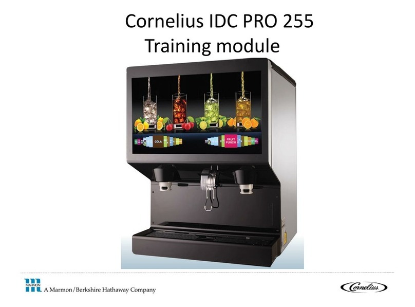
MARMON Cornelius ED300 User manual

Cornelius ED300

Program Information
•Key Contact Information
–Cornelius Technical Service - 800.238.3600 –follow prompts for
technical servive
•M-F 8:00am –5:00pm CST
•www.Cornelius.com -> Resources -> Technical Support
•Warranty
–Dispensers - Two years parts, One year limited labor, five years parts
on the ice bin
–Accessories –One year parts only
2

3
Installation requirements
Voltage: . . . . . . . . . . . . . . . . . . . . . . . . . . . . . . . . . . . . . . . . . . . . . . . . . . 120V / 60Hz / 1Ph
Circuit Amps: . . . . . . . . . . . . . . . . . . . . . . . . . . .Dedicated 15A circuit / Unit total is 5.2FLA
Syrup and Co2 Tubing Size: . . . . . . . . . . . . . . . . . . . . . . . . . . . . . . . 3/8 inch I.D. Minimum
Water Inlet Size: . . . . . . . . . . . . . . 1/2 in supply “T’d” to 2 - 3/8 inch I.D. Lines Minimum
Water Flow Rate: . . . .300 gallons per hour at a minimum flowing pressure of 30-35 psi.
Dimensions: . . . . . . . . . . . . . . . . . . . . . . . . . . . . . . . . . . . . . . . . .44 3/8”W x 31 ½”D x 37”H
Unit Support: . . . . . . . . . . . . . . . . . . . . . . . . . . . . . . . . . . . . . table rated for ~1000 pounds
CO2 pressure to BIB Pumps . . . . . . . . . . . . . . . . . . . . . . . . . . . . . . . . . . . . . . . . .75psi.
Finished Drink Flow Rate: . . . . . . . . . . . . . . . . . . . . . . . . . . . . . . . . . ~ 3.0 ounces / second
- set water flow rate first to 2.5 oz./sec followed by adjusting syrup flow rate
Ratio: . . . . . . . . . . . . . . . . . . . . . . . . . . . . . . . . . . . . . . . . . . .Refer to Product Manufacturer
Notes:
•If Hopper is to be manually filled with Ice, adequate space above the top of the unit
must be allowed.
•Hopper should NEVER be filled with Ice from a freezer as damage may occur. If
bagged ice is to be used it must be left out of the cooler for approximately 15-20
minutes, broken up and removed from the bag.
4
Installation –countertop cutout for
routing lines
Recommended counter
opening size 12” x 15”
for utilities and
beverage tubing.
Opening can be located
anywhere within the
area indicated.

ED300 Cold Plate
5
Cold Plate Drains Water and syrup inlets
Cold Plate Cold Plate

6
ED300 12 valve line-up shown below
ED300 12 valve cold-plate inlets and outlets shown below

ED300 Install Guidelines
7

8
ED300 12 valve Total Flex manifold

ED300 12 valve Total Flex manifold change over
1. Remove the splash panel. Remove the insulation
covers located on the manifolds to expose the
manifold blocks.
Note: Refer to the plumbing diagram on the back
of the splash panel for original factory settings.
2. Locate the water line (1/4” Beverage tubing)
feeding the valve that is to be changed. If the line
is plugged into the back row of holes (in manifold
block),this indicates the valve is plumbed
carbonated. If the line is plugged into the front
row of holes this indicates it is plumbed non-
carbonated.
3. Locate and remove the two (2) screws securing
the retaining clip and remove the clip.
9
Water must be
depressurized if
operational prior to carb
to non-carb changeover

ED300 12 valve Total Flex manifold change over
4. Locate the plastic plug either in front of line or behind line and swap
positions of the plug and water line in manifold block. Repeat this
procedure for other valves to be changed.
5. Reinstall the retaining clip and secure with the screws. The valves
are now hooked up as carb or non-carb depending on how you set
them.
IMPORTANT: All water lines that were involved in this procedure must
be insulated to prevent condensation.
5. Hook-up the water and CO2 supplies to the beverage systems.
Connect the electrical power to the unit.
6. Energize each valve and check for leaks.
7. Reassemble the unit. The unit is now
ready for operation.
10

11
ED300 12 valve Ice Dispensing Guidelines
•Ice height should be controlled by a bin stat that will be supplied by the ice maker
manufacturer
•The ice height should be 4”-6” below the top off the ice hopper
•For nugget / soft ice it should be based off of volume. The lower the volume the lower
the ice level should be and the lower the placement of the bin thermostat. Please
ensure it does not come in contact with the agitators.
•Nugget / soft ice is wetter and heavier ice. If the ice level is not controlled and is
allowed to completely fill the hopper it creates the possibility of bending the agitator
arms which will cause the agitator to cut into the hopper. If you ever see white flakes in
your ice this indicates that the agitator is cutting into the hopper.
•All Cornelius ice combo dispenser ice agitation times come pre set for cubed ice which is
4 sec / 1 hour. For soft ice we want to change the ice agitation to .5 sec / 3 hours. You
will change the agitation times using the potentiometers on the agitation board. ON
cycle will be rotated all the way to the left (.5 Sec) and the OFF cycle will be rotated all
the way to the right (3 hrs).
•To check you set the agitation correctly unplug and plug it in. The agitator will activate
when you plug it in and if it runs for ½ second you did it correct.

12
ED300 12 valve Ice Dispensing Guidelines
Standard cubed Ice typically agitates every 1 hour
for a 4 second stir, should “chewable” Ice settings
need to be set at ½ second every three hour.
Never fill the hopper with Ice from a freezer as
damage may occur.
Restrictor plate must be adjusted according to type
and size of cube.
1.Remove the merchandiser.
2.Loosen but do not remove the four
nuts on the studs that hold the ice chute
onto the ice bin.
3.Once loosened, move the restrictor
plate up to increase opening or down to
decrease opening.
4.Retighten the nuts to 4in. Lbs. and
reinstall the merchandiser. DO NOT
OVERTIGHTEN.

ED300 Ice Dispensing Sequence
13
•The following steps complete the ice dispense sequence
1. Customer engages ice dispense lever which makes contact with the ice dispense push
button located behind the ice dispense lever
2. The ice dispense button closes and sends 120VAC to the agitation board which
activates the agitator.
3. The board then simultaneously converts 120VAC to 106VDC and sends it to the rotary
solenoid. At this time the rotary solenoid lifts the ice gate and the agitator pushes ice
into the ice chute and into the cup.
NOTE: The rotary solenoid is 106VDC and 340ohms +/- 10%
- The most misdiagnosed part on the ED series is the rotary solenoid. If it is not lifting
when you activate the ice dispense lever you want to ensure you have 120VAC to the board
as well as 106VDC to the solenoid. If you have 120VAC to the board and you don’t have
106VDC to the solenoid make sure you check the resistance on the solenoid prior to
swapping the board. If the rotary solenoid has a short in it, it can take the board out as
well.

ED300 soft Ice dispensing ice bin set up
14
Ice drop zones
allows ice to flow
to cold plate
Soft ice agitator arms agitate
ice over the drop zone. Left
rotates CCW and right rotates
CW (looking from front)
Ice diverters help
ice move through
the ice chute.
Different one for
each side

Soft Ice Diverter Installation and Service Details
*ED 300 Digital dispensers come equipped with soft ice kits
15
1. Clean the ice chute area using alcohol.
2. Silicone is added to the ice diverter sides and bottom that come in contact to with the
ice bin, creating a seal around three sides of the ice diverter.

16 Soft Ice Diverter Installation and Service Details Cont.
3. Ice diverter is installed onto the opening, over the ice chute studs.
4. The black gasket is installed over the ice diverter.

17 Soft Ice Diverter Installation and Service Details Cont.
5. The ice restrictor is installed.
6. The red gasket is installed.

18 Soft Ice Diverter Installation and Service Details Cont.
7. Install upper chute. The ice cute is installed and torqued to 4-6 inch
pounds. Warning: overtightening will push the red gaskets below the
bottom of the ice chute, causing a leak.

To check the water and syrup flow rate,
you will need a syrup separator.
1. Install syrup separator, white connector
up. (push up, then twist clockwise)
2. Activate the valve to fill the syrup
separator with syrup, this will prevent
false readings.
19
Setting Ratio (Brix) –installing syrup separator
Syrup separator PN: 319540000

To check the ratio:
1. Dispense sample into correct compartment
as shown.
2. The large portion of the cup is for water and
the smaller chambers are for specific syrup
ratios.
Dispensing into the Ratio / Brix Cup:
20
Post-Mix System Components
Table of contents
Other MARMON Beverage Dispenser manuals
Popular Beverage Dispenser manuals by other brands

McDonald's
McDonald's CORNELIUS AUTOMATED BEVERAGE SYSTEM Operator's manual

LINDR
LINDR PYGMY 30/K prof instruction manual

Cornelius
Cornelius CB1522 installation manual

BIANCHI VENDING
BIANCHI VENDING GAIA STYLE Use and maintenance manual

Dacor
Dacor EF24LBCSS use and care manual

Polar Krush
Polar Krush POL1 operating manual