MARS COMMERCE ZEUS4-VD User manual

ZEUS4-VD
VOICE & SMS GSM ALARM
COMMUNICATOR
INSTALLATION MANUAL
V 2.0

ZEUS4-VD INSTALLATION MANUAL
TABLE OF CONTENTS
1FOR YOUR SAFETY................................................................................................................1
2INTRODUCTION......................................................................................................................2
3FEATURES AND APPLICATIONS .......................................................................................3
4START UP..................................................................................................................................4
5LED DISPLAY...........................................................................................................................5
6CLEAR ALL PROGRAMMED DATA FROM SIM.............................................................6
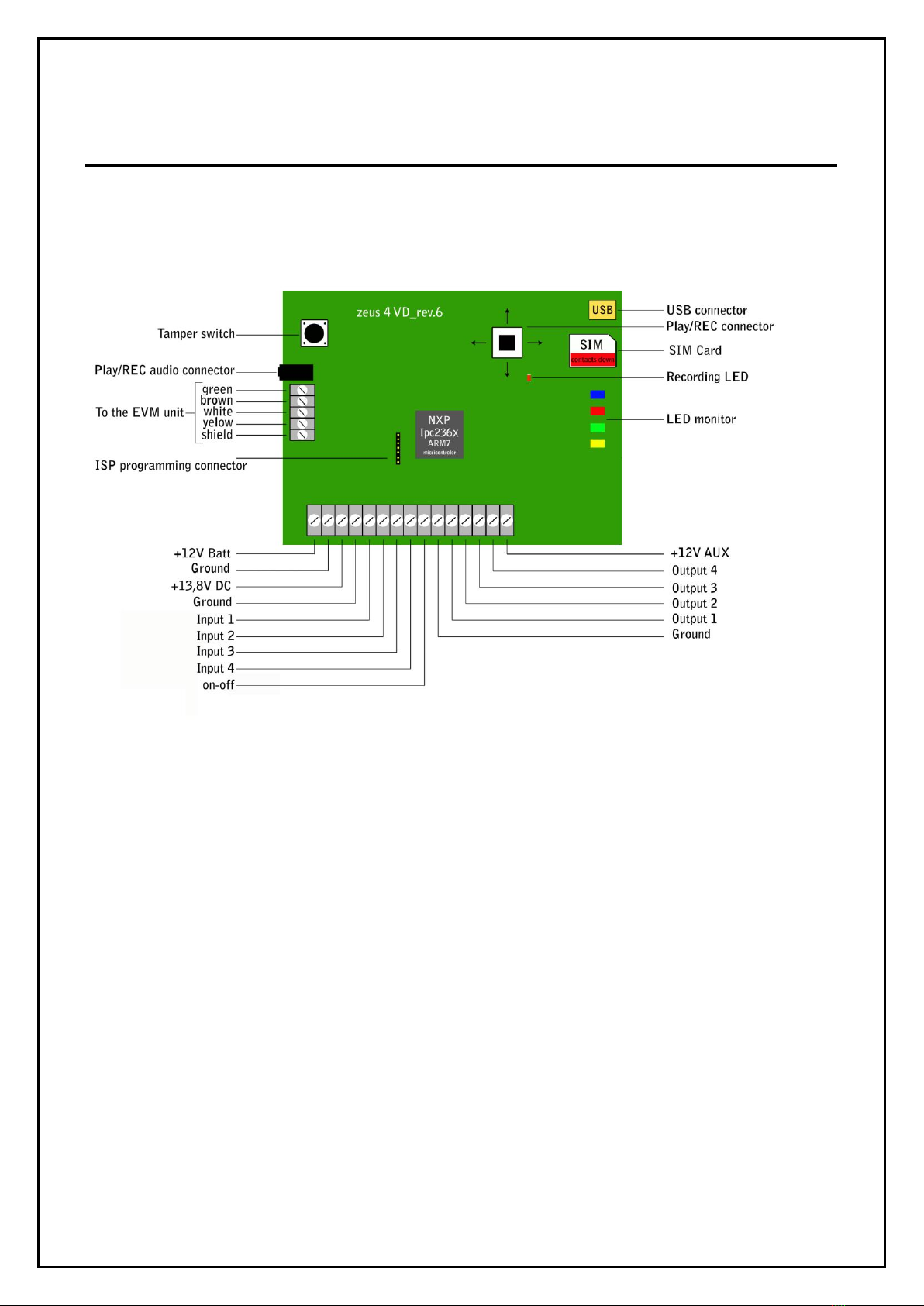
7CONNECTING DIAGRAM.....................................................................................................7
8VOICE MESSAGES –RECORD & PLAY............................................................................8
8.1 RECORDING MODE..............................................................................................................8
8.2 PLAY.......................................................................................................................................8
9PROGRAMMING MODE........................................................................................................9
9.1 PROGRAMMING TELEPHONE NUMBERS -TN...............................................................9
9.2 PROGRAMMING INPUT STATUS -IN..............................................................................10
9.1 INPUTS AND TELEPHONE NO. LINKING -LN...............................................................12
9.2 MAIN POWER LOST AND TELEPHONE NO. LINKING –LN5......................................13
9.3 LOW BATTERY AND TELEPHONE NO. LINKING –LN6..............................................13
9.4 MAIN POWER LOST FILTER PARAMETER -MAIN ......................................................14
9.5 INPUT FILTER PARAMETR –ID .......................................................................................15
9.6 DELAY BEFORE DIAL –DD ..............................................................................................16
9.7 PROGRAMMING OUTPUT STATUS -OS.........................................................................17
9.8 DIRECT ALARM OUTPUT –OD........................................................................................18
9.9 CLIP FUNCTION PARAMETER –TC ................................................................................19
9.1 AUTOMATIC INPUT BLOCK SYSTEM............................................................................20
9.2 SECURITY LEVEL -SL.......................................................................................................21
9.3 PREPAID CARD CREDIT AND VALIDITY INFORMATION..........................................22
9.4 SET-UP PARAMETERS.......................................................................................................22
9.5 SMS MESSAGES EDITOR ..................................................................................................25
10 DTMF REMOTE COMMANDS............................................................................................26
10.1 DTMF REMOTE COMMAND TABLE ...........................................................................26
11 PRINT-OUT OF THE PARAMETERS ................................................................................27
11.1 RECEIVE ALL PARAMETERS (PALL) .........................................................................27
11.2 RECEIVE TELEPHONE NUMBERS (PTN)....................................................................27
11.3 RECEIVE LINKS (PLN)...................................................................................................27
11.4 RECEIVE INPUT PARAMETERS (PIN).........................................................................27

ZEUS4-VD INSTALLATION MANUAL
11.5 RECEIVE INPUT FILTER VALUE (PID)........................................................................27
11.6 RECEIVE DELAY BEFORE DIAL VALUE (PDD)........................................................27
11.7 RECEIVE CLIP IDENTIFICATION FUNCTIONS (PTC) ..............................................27
11.8 RECEIVE ACCESS TELEPHONE NUMBERS (PSL) ....................................................28
11.9 RECEIVE OUTPUT PARAMETERS (POS)....................................................................28
11.10 RECEIVE LINK FOR LOCAL ALARM OUTPUT (POD) ..............................................28
11.11 RECEIVE ALL PROGRAMMED SMS MESSAGES (P#)...............................................28
11.12 RECEIVE THE POWER LEVEL ON THE UNIT (PPWR)..............................................28
11.13 RECEIVE SET UP PARAMETERS VALUE (PPA).........................................................28
11.14 STATE OF THE CREDIT FOR THE PREPAID CARD...................................................28
11.15 STATE OF THE OUTPUTS (PORC)................................................................................28
12 CHECKING AND CHANGING THE SYSTEM STATUS (ON/OFF)..............................29
12.1 CHECKING SYSTEM STATUS BY SMS COMMAND.................................................29
12.2 CHECKING SYSTEM STATUS BY DTMF COMMAND..............................................29
12.3 CHANGING SYSTEM STATUS TO ON (SYSTEM ON) ...............................................29
12.4 CHANGING SYSTEM STATUS TO OFF (SYSTEM OFF)............................................29
13 CHECKING THE INPUT STATUS......................................................................................30
13.1 CHECKING THE INPUT STATUS BY DTMF................................................................30
13.2 CHECKING THE INPUT STATUS BY SMS (INS).........................................................30
14 OUTPUTS REMOTE CONTROL.........................................................................................31
14.1 OUTPUTS REMOTE CONTROL BY SMS COMMAND ...............................................31
14.2 OUTPUTS REMOTE CONTROL BY DTMF COMMAND ............................................31
15 CHANGING PARAMETERS USING THE SMS COMMAND.........................................32
16 APPENDIX TO ZEUS4-VD MANUAL FOR CONTACT-ID (REV6) ..............................33
17 TECHNICAL SPECIFICATION...........................................................................................34
18 CONTACTS .............................................................................................................................35

ZEUS4-VD INSTALLATION MANUAL
1
1FOR YOUR SAFETY
Read these simple guidelines. Not following them may be dangerous or illegal. Read the complete
user guide for further information.
SWITCH ON SAFELY
Do not switch the unit on when use of wireless phone is prohibited or when it may cause
interference or danger.
INTERFERENCE
All wireless phones and units may be susceptible to interference, which could affect performance.
SWITCH OFF IN HOSPITALS
Follow any restrictions. Switch the unit off near medical equipment.
SWITCH OFF IN AIRCRAFT
Follow any restrictions. Wireless devices can cause interference in aircraft.
SWITCH OFF WHEN REFUELING
Do not use the unit at a refueling point. Do not use near fuel or chemicals.
SWITCH OFF NEAR BLASTING
Follow any restrictions. Do not use the unit where blasting is in progress.
USE SENSIBLY
Use only in the normal position as explained in the product documentation. Do not touch the
antenna unnecessarily.

ZEUS4-VD INSTALLATION MANUAL
2
2INTRODUCTION
ZEUS4-VD communicator is a new mobile voice and SMS autodialing system. It is mostly used to
provide wide range of alarm information and very useful remote controls. ZEUS4-VD can pass on
messages about intrusion alarms, technical alarms, etc. by voice call or SMS to the end-user or
directly by sending the Contact ID built-in to the Central Monitoring Station (CMS).
ZEUS4-VD can be used in connection with different applications such as:
Security alarm systems
Home care and Emergency alarm
Fire systems
Car and boat alarm transmitter
Door entry
Remote access control

ZEUS4-VD INSTALLATION MANUAL
3
3FEATURES AND APPLICATIONS
Features:
Built-in 3 or 4 band GSM module
Contact ID protocol built-in
4 alarm inputs
ON/OFF input
4 remotely controlled alarm outputs
4 prerecorded alarm messages –1 for each alarm input
15 SMS alarm and service messages
Memory stores up to 10 different telephone numbers
Listen-in function
PC programming by USB SIM card editor
Download programming by USB port
Output remotely controlled by SMS, CLIP and DTMF command
System activating and deactivating by SMS, CLIP and DTMF command
Up to 1000 event log buffer
Applications:
Security alarm systems
Home care and Emergency alarm
Fire systems
Car and boat alarm transmitter
Door entry
Remote access control
Temperature regulations
Vending Machines
Other remote controls

ZEUS4-VD INSTALLATION MANUAL
4
4START UP
Insert SIM card to be used for ZEUS4-VD in your personal mobile phone.
ERASE THE PIN CODE!
Enter telephone numbers and the required operating parameters in SIM memory –at least 1
telephone No. (TN1) and 1 link (LN1) should be programmed (see installation manual).
Insert SIM card in the GSM module applied for the ZEUS4-VD device. The unit must be
power OFF when you insert the SIM!
Connect alarm inputs and outputs to ZEUS4-VD.
Connect the antenna to antenna connector.
Connect device to source power supply voltage.
Wait until LED3 display is turned ON (green) and LED1 (blue) starts flashing. This is set in
around 1 minute.
Connect the headset to Play/REC connector and record alarm messages.
ZEUS4-VD unit is now ready to operate.
NOTE: When the back-up battery 12V/1,2Ah is connected to the unit the main power supply
must be from 13,8V to 14,5V DC!

ZEUS4-VD INSTALLATION MANUAL
5
5LED DISPLAY
Blue LED (LED1)
-Indicates the level of the GSM signal from 1 to 5 LED flashes (1 is weak signal, 5 is
excellent signal)
Red LED (LED2)
-When LED 2 is ON the unit has a problem with a GSM network connection or the GSM
part of the unit is out of order. In this case immediately call the service!
Red LED (LED2) –alarm state
-During an alarm event the red LED indicates on which input alarm has been triggered. For
example if alarm was triggered on the first input there is 1 LED flash, on second input 2
LED flashes, etc.
Green LED (LED3)
-When the alarm inputs on the unit are in active state (SYS=1) then the green LED is ON.
With alarm inputs disabled the green LED goes OFF (SYS=0).
Yellow LED (LED4)
-Short flashing indicates that the GSM module is ON, but it is not yet connected on the GSM
network. After connection, yellow led is flashing with short pulse ON and a long pulse OFF.

ZEUS4-VD INSTALLATION MANUAL
6
6CLEAR ALL PROGRAMMED DATA FROM SIM
WARNING!!! By sending this command to the ZEUS4-VD all programmed data are erased
from the SIM card!
This is highly recommended when a SIM card you are going to use for the ZEUS4-VD is not new
and it already has some data stored in the phone book memory.
By sending this SMS to ZEUS4-VD all programmed parameters and numbers are cleared:
;SDCLR;
After sending SMS you should wait at least 30 second for the command to be executed!

ZEUS4-VD INSTALLATION MANUAL
7
7CONNECTING DIAGRAM

ZEUS4-VD INSTALLATION MANUAL
8
8VOICE MESSAGES –RECORD & PLAY
The memory of each alarm input enables us to record our own voice message in the total length of
10 seconds. The device is namely equipped with a PLAY/REC audio connector. For recording and
listening recorded message a headset is necessary. Headset is very common and it is use with many
mobile phones but should be supplied also by your distributor.
8.1 RECORDING MODE
For recording and playing alarm messages ZEUS4-VD has a joystick switch which you can use in 4
different directions:
Message 1 –UP
Message 2 –RIGHT
Message 3 –DOWN
Message 4 –LEFT
message 1
message 4
message 3
message 2
To start recording mode push the PLAY/REC joystick into one direction (depending which message
you would like to record) and hold the stick in this position. After the beep you can start with
recording and stop recording when you hear two short beeps. REC/PLAY procedure is indicating
by REC/PLAY LED as well. REC/PLAY LED is flashing during recording or playing procedure.
Follow the same procedure for all four alarm messages.
8.2 PLAY
Press the PLAY/REC joystick into one direction for a short time (around 1 second) and you will
hear the recorded message.
To stop play mode press the PLAY/REC joystick again for a second and play mode will stop.
Follow the same procedure for all four messages.

ZEUS4-VD INSTALLATION MANUAL
9
9PROGRAMMING MODE
IMPORTANT!!!
Before you insert SIM card into the holder of GSM module or external GSM phone please
disable the PIN CODE!!!!
To program ZEUS4-VD parameters put the SIM card into your personal GSM phone. Add
programming parameters in SIM Card “Phone Book”.
ZEUS4-VD is possible to program on 4 different ways:
Using the USB SIM manager on the PC - recommended
Directly on SIM card using personal mobile phone
Remotely by SMS command
With PC Via USB port*
* Not supported yet
NOTE: When you use new or empty SIM card or when parameters were not yet programmed
ZEUS4-VD automatically sets the default values (see table).
9.1 PROGRAMMING TELEPHONE NUMBERS - TN
PROGRAMMING TABLE –DIRECT PROGRAMMING ON THE SIM CARD
Default values:
ZEUS4-VD PROGRAMMING TABLE
SIM CARD PHONE BOOK
Name
Number (Default)
Description
TN1
1st telephone number
TN2
2nd telephone number
TN3
3rd telephone number
TN4
4th telephone number
TN5
5th telephone number
TN6
6th telephone number
TN7
7th telephone number
TN8
8th telephone number
TN9
9th telephone number
TN0
10th telephone number
ZEUS4-VD sends an alarm prerecorded voice messages, an alarm SMS messages or both. If the
corresponding name ends with the letter “V”, only voice message is sent and if the name ends with
the letter “M” only SMS message is sent.
By pressing * on your phone you switch OFF the redial call for calling number. The
remaining numbers are called as usual. By pressing # you switch off all remaining calls.

ZEUS4-VD INSTALLATION MANUAL
10
Example: When you need to send an alarm beep message and SMS message to the first telephone
number, only alarm beep message to the second one and only SMS message to the third one. (See
the table below.)
ZEUS4-VD PROGRAMMING TABLE
SIM CARD PHONE BOOK
Name
Number
Description
TN1
042376678
1st telephone number (alarm voice & SMS message)
TN2V
040719479
2nd telephone number (alarm voice only)
TN3M
040308350
3rd telephone number (SMS message only)
9.1.1 TN remote programming by SMS
For the upper example send the following SMS from the host phone to the ZEUS4-VD:
;TN1=042376678;TN2V=040719479;TN3M=040308350;
If you would like to receive confirmation SMS write “+” before SMS command:
;+TN1=042376678;TN2V=040719479;TN3M=040308350;
9.2 PROGRAMMING INPUT STATUS - IN
Alarm and reset input can be triggered in 4 different ways. The status of the input can either be
normal closed (N.C) or normal open (N.O.) with positive (+ 12V) or negative (GND) voltage.
When you need the input feedback information it is possible to receive SMS back when input will
return from alarm to normal position. (See cap.5.8 –SMS Messages organizer). To get return SMS
use IN=4,5 or 6.
IN = 0 –Normal Open –triggered with negative voltage (GND)
IN = 1 –Normal Close –breaking negative or positive voltage loop
IN = 2 –Normal Open –triggered with positive voltage (+ 12VDC)
IN = 3 –Input disable
IN = 4 = IN = 0 + input reset SMS
IN = 5 = IN = 1 + input reset SMS
IN = 6 = IN = 2 + input reset SMS

ZEUS4-VD INSTALLATION MANUAL
11
TYPICAL INPUT CONNECTIONS
GND
INPUT 1-4
N.O.
contact
+12V DC
INPUT 1-4
N.O.
contact
GND
1-4INPUT
N.C.
contact
+12V DC
INPUT 1-4
N.O.
contact
PROGRAMMING TABLE FOR INPUT STATUS
Default values:
ZEUS4-VD PROGRAMMING TABLE
SIM CARD PHONE BOOK
Name
Number (Default)
Description
ION
0
Input status for system ON/OFF
IN1
0
Input status for alarm input 1
IN2
0
Input status for alarm input 2
IN3
0
Input status for alarm input 3
IN4
0
Input status for alarm input 4
Example:
ZEUS4-VD PROGRAMMING TABLE
SIM CARD PHONE BOOK
Name
Number
Description
ION
0
OFF –connecting GND on ON/OFF input
IN1
0
Alarm activated by connecting to GND
IN2
1
Alarm activated by disconnecting GND or +12V
IN3
2
Alarm activated by connecting +12V
IN4
4
Alarm activated by connecting to GND + RST SMS
9.2.1 IN parameter remote programming by SMS
For the upper example send the following SMS from the host phone to the ZEUS4-VD:
;ION=0;IN1=0;IN2=1;IN3=2;IN4=4;
If you would like to receive confirmation SMS write “+” before SMS command:
;+ION=0;IN1=0;IN2=1;IN3=2;IN4=4;

ZEUS4-VD INSTALLATION MANUAL
12
9.1 INPUTS AND TELEPHONE NO. LINKING - LN
It is possible to link each number or any combination of numbers to any of the four corresponding
inputs.
9.1.1 Programming table for linking the inputs and telephone numbers –LN
Default values:
ZEUS4-VD PROGRAMMING TABLE
SIM CARD PHONE BOOK
Name
Number (Default)
Description
LN1
Input & telephone No. linking for 1st alarm input (TN1 –TN0)
LN2
Input & telephone No. linking for 2nd alarm input (TN1 –TN0)
LN3
Input & telephone No. linking for 3rd alarm input (TN1 –TN0)
LN4
Input & telephone No. linking for 4th alarm input (TN1 –TN0)
LN5
Power down and telephone No. linking (TN1 –TN0)
LN6
Low Battery and telephone No. Linking (TN1 –TN0)
LN7
Periodic test SMS and telephone No. linking (TN1 –TN0)
LN8
SIM card refill and telephone No. linking (TN1 –TN0)
LN9
Tamper switch and telephone No. linking (TN1 –TN0)
Example:
ZEUS4-VD PROGRAMMING TABLE
SIM CARD PHONE BOOK
Name
Number
Description
LN8
12
Refill SIM –SMS is sent to TN1 & TN2
LN1
13
Input1 is called/sent SMS to TN1 & TN3
LN2
123
Input2 is called/sent SMS to TN1, TN2 & TN3
LN3
5
Input3 is called/sent SMS to TN5
LN4
45
Input4 is called/sent SMS to send to TN4 & TN5
LN7
12
Periodic Test SMS is sent to TN1 & TN2
9.1.2 LN remote programming by SMS
For the upper example send the following SMS from the host phone to the ZEUS4-VD:
;LN8=12;LN1=13;LN2=123;LN3=5;LN4=45;LN7=12;
If you would like to receive confirmation SMS write “+” before SMS command:
;+LN8=12;LN1=13;LN2=123;LN3=5;LN4=45;LN7=12;

ZEUS4-VD INSTALLATION MANUAL
13
9.2 MAIN POWER LOST AND TELEPHONE NO. LINKING –LN5
ZEUS4-VD sends an SMS message in case of the main power failure. SMS message is sent to user.
The default SMS is “Main Power Lost”. You can also program how long the unit can stay without
power before sending this message. The default time is 5 second (parameter MAIN).
9.2.1 Programming table for the MAIN POWER LOST and telephone numbers linking
Default values:
ZEUS4-VD PROGRAMMING TABLE
SIM CARD PHONE BOOK
Name
Number (Default)
Description
LN5
Telephone number from TN1 to TN0
Example:
ZEUS4-VD PROGRAMMING TABLE
SIM CARD PHONE BOOK
Name
Number
Description
LN5
12
Main Power Lost SMS is sent to TN1 and TN2
9.2.2 LN remote programming by SMS
For the upper example send the following SMS from the host phone to the ZEUS4-VD:
;LN5=12;
If you would like to receive confirmation SMS write “+” before SMS command:
;+LN5=12;
9.3 LOW BATTERY AND TELEPHONE NO. LINKING –LN6
ZEUS4-VD can control battery level and sends 3 SMS messages when following voltage level on
battery is reached: 11,5V, 10,5V and 9V. It sends the “Low Battery” and battery level in volts SMS
message together.
The low battery level can be detected when the unit works without main power supply.
Should the battery power rise again above 11,5V ZEUS4-VD sends an SMS message with the
following text: “Low Battery restored”.
NOTE: The “Low battery” event is detected when the ZEUS4-VD operates only with a
backup battery and it is not connected on the Main Power Supply.

ZEUS4-VD INSTALLATION MANUAL
14
9.3.1 Programming table for LOW BATTERY and telephone numbers linking
Default values:
ZEUS4-VD PROGRAMMING TABLE
SIM CARD PHONE BOOK
Name
Number (Default)
Description
LN6
Telephone number from TN1 to TN0
Example:
ZEUS4-VD PROGRAMMING TABLE
SIM CARD PHONE BOOK
Name
Number
Description
LN6
12
Low Battery SMS is sent to TN1 and TN2
9.3.2 LN6 remote programming by SMS
For the upper example send the following SMS from the host phone to the ZEUS4-VD:
;LN6=12;
If you would like to receive confirmation SMS write “+” before SMS command:
;+LN6=12;
9.4 MAIN POWER LOST FILTER PARAMETER - MAIN
Parameter MAIN determinates length of the pulse which is required to trigger the alarm after the
main power is lost. Time can be set between 1 and 9999 seconds. The default value is 5 seconds.
For example: When ZEUS4-VD is without main power supply for more than 5 seconds (default) it
sends an SMS message with the following text: “Main Power Lost”.
Should the main power return ZEUS4-VD sends an SMS message with the following text: “Main
Power restored”.
9.4.1 Programming table for “MAIN POWER LOST” filter – MAIN
Default values:
ZEUS4-VD PROGRAMMING TABLE
SIM CARD PHONE BOOK
Name
Number (Default)
Description
MAIN
5
Main Power Lost filter (5 seconds default)

ZEUS4-VD INSTALLATION MANUAL
15
Example:
ZEUS4-VD PROGRAMMING TABLE
SIM CARD PHONE BOOK
Name
Number
Description
MAIN
9
Main Power Lost filter
9.4.2 MAIN POWER LOST - filter remote programming by SMS
For the upper example send the following SMS from the host phone to the ZEUS4-VD:
;MAIN=9;
If you would like to receive confirmation SMS write “+” before SMS command:
;+MAIN=9;
9.5 INPUT FILTER PARAMETR –ID
ID parameter determines time period of the pulse length to trigger the Input. The pulse time can be
from 0,5 seconds to 9999 seconds. The default time is 0,5 seconds when the parameter value is 0.
9.5.1 Programming table to define the value of the input filter
Default values:
ZEUS4-VD PROGRAMMING TABLE
SIM CARD PHONE BOOK
Name
Number (Default)
Description
DON
0
Default ID filter is 0,5 seconds –ON/OFF input
ID1
0
Default ID filter is 0,5 seconds –input 1
ID2
0
Default ID filter is 0,5 seconds –input 2
ID3
0
Default ID filter is 0,5 seconds –input 3
ID4
0
Default ID filter is 0,5 seconds –input 4
Example:
ZEUS4-VD PROGRAMMING TABLE
SIM CARD PHONE BOOK
Name
Number
Description
DON
0
Default ID filter is 0,5 seconds –ON/OFF input
ID1
5
ID filter is 5 seconds for input 1
ID2
30
ID filter is 30 seconds for input 2
ID3
2
ID filter is 2 seconds for input 3
ID4
0
ID filter is 0,5 seconds for input 4

ZEUS4-VD INSTALLATION MANUAL
16
9.5.2 ID parameter remote programming by SMS
For the upper example send the following SMS from the host phone to the ZEUS4-VD:
;ID1=5;ID2=30;ID3=2;ID4=0;
If you would like to receive confirmation SMS write “+” before SMS command:
;+ID1=5;ID2=30;ID3=2;ID4=0;
9.6 DELAY BEFORE DIAL –DD
If you would like to have a delay before unit starts dialing procedure use DD –delay before dialing
parameter.
Default values:
ZEUS4-VD PROGRAMMING TABLE
SIM CARD PHONE BOOK
Name
Number (Default)
Description
DDN
ON/OFF input delay
DD1
Delay before dialing for Input 1
DD2
Delay before dialing for Input 2
DD3
Delay before dialing for Input 3
DD4
Delay before dialing for Input 4
Example:
ZEUS4-VD PROGRAMMING TABLE
SIM CARD PHONE BOOK
Name
Number
Description
DDN
15
15 seconds delay for ON/OFF input
DD1
5
5 seconds delay before dialing for Input 1
DD2
0
No delay before dialing for Input 2
DD3
0
No delay before dialing for Input 3
DD4
10
10 seconds delay before dialing for Input 4
9.6.1 DD remote programming by SMS
For the upper example send the following SMS from the host phone to the ZEUS4-VD:
;DDN=15;DD1=5;DD2=0;DD3=0;DD4=10;
If you would like to receive confirmation SMS write “+” before SMS command:
;+DDN=15;DD1=5;DD2=0;DD3=0;DD4=10;

ZEUS4-VD INSTALLATION MANUAL
17
9.7 PROGRAMMING OUTPUT STATUS - OS
ZEUS4-VD device has 4 open collector outputs and each of them can be programmed through
network in a different way: as a bi-stable or mono-stable (pulse) output. The programming time is
in seconds.
Typical connection for the output:
+12V DC
OUTPUT 1-4
R1K
LED
+12V DC
1-4OUTPUT
RELAY
12V DC
9.7.1 Programming table for output status
Default values:
ZEUS4-VD PROGRAMMING TABLE
SIM CARD PHONE BOOK
Name
Number (Default)
Description
OS1
1
Status for the 1st output –enabled
OS2
1
Status for the 2nd output –enabled
OS3
1
Status for the 3rd output –enabled
OS4
1
Status for the 4th output –enabled
Example:
ZEUS4-VD PROGRAMMING TABLE
SIM CARD PHONE BOOK
Name
Number
Description
OS1
1
ON/OFF mode output
OS2
0
Disabled output
OS3
20
20 second pulse output
OS4
5
5 second pulse output
9.7.2 OS remote programming by SMS
For the upper example send the following SMS from the host phone to the ZEUS4-VD:
;OS1=1;OS2=0;OS3=20;OS4=5;
If you would like to receive confirmation SMS write “+” before SMS command:
;+OS1=1;OS2=0;OS3=20;OS4=5;
Other manuals for ZEUS4-VD
1
Table of contents
Other MARS COMMERCE Cell Phone manuals