MARS COMMERCE ZEUS4 User manual

ZEUS4
(ZEUS4-MC, ZEUS4-MC LITE)
(ZEUS4-VD, ZEUS4-VD LITE)
VOICE & SMS GSM ALARM COMMUNICATOR
USER MANUAL

ZEUS4
USER MANUAL
Page 1
Contents
1FOR YOUR SAFETY.............................................................................................................................................3
2INTRODUCTION...................................................................................................................................................4
3ZEUS4-VD FEATURES AND APPLICATIONS ................................................................................................5
4START UP...............................................................................................................................................................6
5LED INDICATION.................................................................................................................................................7
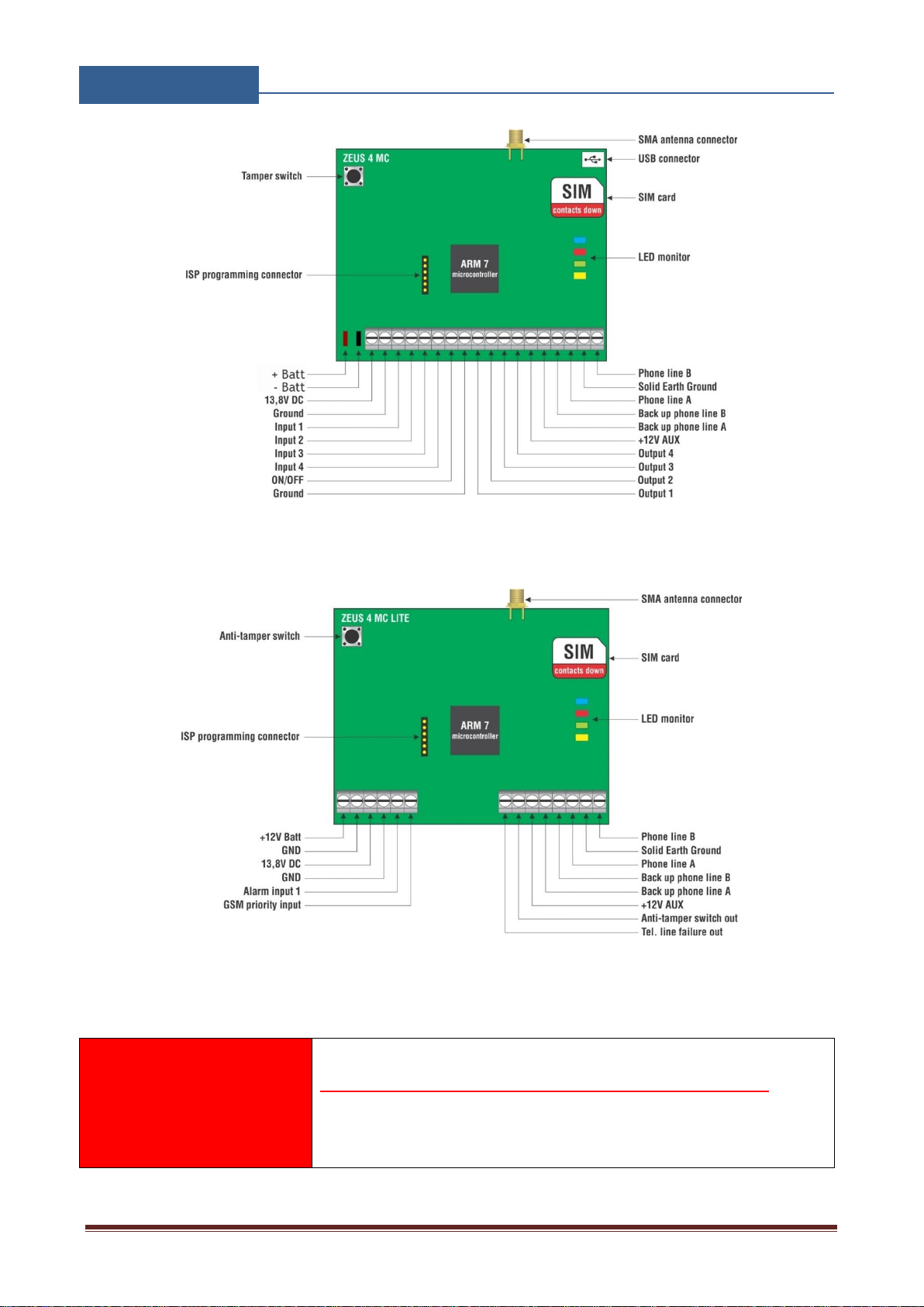
6CONNECTION DIAGRAM ..................................................................................................................................8
7ZEUS4 UNIT MANAGEMENT ..........................................................................................................................10
8ZEUS4 FUNCTIONS WITH PROGRAMMING INSTRUCTIONS ...............................................................11
8.1 WEB SERVER - LOG IN..................................................................................................................................................11
8.2 WEB SERVER –ADDING UNITS TO USER PROFILE................................................................................................12
8.3 WEB SERVER-UNIT MANAGEMENT ..........................................................................................................................14
8.4 CALLER ID ACCESS.......................................................................................................................................................15
8.5 OUTPUTS SETTINGS......................................................................................................................................................16
8.6 INPUTS SETTINGS..........................................................................................................................................................18
8.7 ADMINISTRATION.........................................................................................................................................................20
8.8 MISCELLANEOUS ..........................................................................................................................................................22
8.9 ALARM IP CONFIGURATION.......................................................................................................................................23
8.10 GENERAL SETTINGS .....................................................................................................................................................24
9CONTACTS ..........................................................................................................................................................26

ZEUS4
USER MANUAL
Page 2
Figures
Figure 1: ZEUS4: ZEUS4-VD Connection diagram ...........................................................................8
Figure 2: ZEUS4: ZEUS4-MC Connection diagram...........................................................................9
Figure 3: ZEUS4: ZEUS4-MC LITE Connection diagram .................................................................9
Figure 4: WEB Server-Sign In page..................................................................................................11
Figure 5: WEB Server-Main page select ADD mode........................................................................12
Figure 6: WEB Server-Main page adding ZEUS4 units....................................................................12
Figure 7: WEB Server-Unit management window............................................................................14
Figure 8: WEB Server-Caller ID Access...........................................................................................15
Figure 9: WEB Server-Output setting................................................................................................16
Figure 10: WEB Server-Input setting ................................................................................................18
Figure 11: WEB Server-Notification numbers ..................................................................................20
Figure 12: WEB Server-Misc ............................................................................................................22
Figure 13: WEB Server-Alarm IP configuration...............................................................................23
Figure 14: WEB Server - ZEUS4-VD General configuration..........................................................24
Figure 15: WEB Server - ZEUS4-MC General configuration..........................................................24

ZEUS4
USER MANUAL
Page 3
1FOR YOUR SAFETY
SWITCH ON SAFELY
Do not switch the unit on when use of wireless phone is prohibited or when it may cause
interference or danger.
INTERFERENCE
All wireless phones and units may be susceptible to interference, which could affect performance.
SWITCH OFF IN HOSPITALS
Follow any restrictions. Switch the unit off near medical equipment.
SWITCH OFF IN AIRCRAFT
Follow any restrictions. Wireless devices can cause interference in aircraft.
SWITCH OFF WHEN REFUELING
Do not use the unit at a refueling point. Do not use near fuel or chemicals.
SWITCH OFF NEAR BLASTING
Follow any restrictions. Do not use the unit where blasting is in progress.
USE SENSIBLY
Use only in the normal position as explained in the product documentation. Do not touch the
antenna unnecessarily.

ZEUS4
USER MANUAL
Page 4
2INTRODUCTION
ZEUS4 family of devices are a simple GSM alarm gateway system designed to ensure low-cost,
simple to install/use, reliable and single box solution for alarm gateway application. It is designed
for unlimited range, wire free alarm application.
ZEUS4-VD and it’s ZEUS4-VD LITE derivative is designed for standalone applications and it can
be used as a simple alarm system.
ZEUS4-MC and it’s ZEUS4-MC LITE derivative is designed as replacement for old telephone line
for alarm centrals. It allows the costumer to continue to use there old alarm centrals with the NEW
IP alarm centrals.
Optional ZEUS4 supports alarm detection, stay-alive messages, credit detection etc…
NOTE
Some functions are only supported on particular model in the ZEUS4 family
line up.

ZEUS4
USER MANUAL
Page 5
3ZEUS4-VD FEATURES AND APPLICATIONS
Features:
Built-in GSM (LTE) module
Up-to 10 Alarm notification numbers
Caller ID numbers control (up-to 10 caller ID numbers)
Build in IP alarm reporting
4 x Alarm Inputs
4 x Outputs
POTS line simulation
Programming by WEB server
Programming by Android and IOS apps
Applications:
Single box, wire free alarm system
Remote gate opener –Caller ID number recognition

ZEUS4
USER MANUAL
Page 6
4START UP
ZEUS4 unit accepts a standard GSM SIM card from any network.
VERY
IMPORTANT
USE A MICRO SIM CARD
WARNING
DO NOT Insert or remove the SIM card while the unit is powered ON!!
IMPORTANT
Before inserting SIM card to unit make sure the PIN code is
removed!!
Insert SIM card in ZEUS4 unit.
Connect power cable to ZEUS4 unit (YOU MUST POWER THE ZEUS4 UNIT WITH
THE POWER SUPPLY INCLUDED). Do not power with any other power supply.
Power up the unit.
Wait until LED1 (Blue) starts flashing. This is set in around 30 –45 seconds.
ZEUS4 unit is now ready to operate.

ZEUS4
USER MANUAL
Page 7
5LED INDICATION
Blue LED (LED1)
–Indicates the level of the GSM signal from 1 to 5 LED flashes (1 is weak signal, 5 is
excellent signal)
Red LED (LED2)
-When LED 2 is ON the unit has a problem with a GSM network connection or the GSM
part of the unit is out of order. In this case immediately call the service!
Red LED (LED2) –alarm state
-During an alarm event the red LED indicates on which input alarm has been triggered. For
example if alarm was triggered on the first input there is 1 LED flash, on second input 2
LED flashes, etc.
Green LED (LED3)
-When the alarm inputs on the unit are in active state (SYS=1) then the green LED is ON.
With alarm inputs disabled the green LED goes OFF (SYS=0).
Yellow LED (LED4)
-Short flashing indicates that the GSM module is ON, but it is not yet connected on the GSM
network. After connection, yellow led is flashing with short pulse ON and a long pulse OFF.

ZEUS4
USER MANUAL
Page 8
6CONNECTION DIAGRAM
Before connection the ZEUS4 please take a look at connection diagram for particular module.
Figure 1: ZEUS4: ZEUS4-VD Connection diagram

ZEUS4
USER MANUAL
Page 9
Figure 2: ZEUS4: ZEUS4-MC Connection diagram
Figure 3: ZEUS4: ZEUS4-MC LITE Connection diagram
IMPORTANT
DO NOT USE Power out (12V AUX) for electric lock driving!
Useseparatepower sourcefordoorelectriclock!

ZEUS4
USER MANUAL
Page 10
7ZEUS4 UNIT MANAGEMENT
Unit supports different types of management (programming):
Unit can be programmed remotely by using WEB server access
Unit can be programmed remotely by using Smartphone apps (Android and IOS).
Unit can be programmed remotely by SMS commands (Optional).

ZEUS4
USER MANUAL
Page 11
8ZEUS4 FUNCTIONS WITH PROGRAMMING
INSTRUCTIONS
As mentioned in previous chapters ZEUS4 unit can be programmed in various ways, this document
will focus on most common programming way: WEB programming.
IMPORTANT
SIM card in the ZEUS4 unit MUST have DATA PLAN to be able to use
WEB programming!
8.1 WEB SERVER - LOG IN
The web server can be found under the address: https://www.easyset.eu/.
Figure 4: WEB Server-Sign In page
User must first use the Sign IN section to create working profile on the server. The profile can be
created by using social login like Facebook, Google account or Twitter. If user lacks any of the
social profile it can proceed to Sign UP page use standard user name and password entry.

ZEUS4
USER MANUAL
Page 12
NOTE
Server support Firefox, Google Chrome, Safari.
8.2 WEB SERVER –ADDING UNITS TO USER PROFILE
After login the user will be diverted to WEB server main window. This page is used to
add/remove/search for ZEUS4 units from the user’s profile.
Select “+” sign to select ADD ZEUS4 units to user’s profile.
Figure 5: WEB Server-Main page select ADD mode
Figure 6: WEB Server-Main page adding ZEUS4 units

ZEUS4
USER MANUAL
Page 13
User than provides required data:
•Name: Name for the added unit - mandatory information.
•IMEI: Identification number of the unit can be found in the enclosure of the unit -
mandatory information. The IMEI is located on the cellular chip and also should be on the
card board box of the ZEUS4.
•Phone Number: The telephone number of the SIM card in the ZEUS4 unit - mandatory
data.
•SIM provider: Information needed to enable data connection between the server and the
unit. Selectable from the drop-down menu - mandatory data.
•Location: Notification field, used by the user to provide extra data for its own information -
optional data.
First building of the unit data-base may take a few minutes.

ZEUS4
USER MANUAL
Page 14
8.3 WEB SERVER-UNIT MANAGEMENT
After the ZEUS4 unit is added to user database, the user can change the configuration of the
specific unit.
All changes made by the user are listed in the Change Log window. By clicking Send to device
button ALL changes are sending to the unit.
Figure 7: WEB Server-Unit management window

ZEUS4
USER MANUAL
Page 15
8.4 CALLER ID ACCESS
Caller ID access is a very simple way to control relay output defined in Caller ID output setting.
User will by calling in the ZEUS4 unit trigger defined output.
Settings for this function are found in the Caller id # tab.
Figure 8: WEB Server-Caller ID Access
General settings:
•Caller ID security mode: User can select between 3 options:
Caller ID Disabled deactivates caller ID function –all numbers are restricted.
Caller ID for specific users will limit the caller ID function only to the numbers on the list.
Caller ID always ON will allow all users that know the number of the unit to open defined
output. In last option the user doesn’t need to be on the list to trigger the output.
•Caller ID output: Selecting the output that will be triggered in Caller ID function.
NOTE
Selection Caller ID always ON will allow anybody with the knowledge of the
unit number to trigger the output by calling the unit. Use this setting with
caution.

ZEUS4
USER MANUAL
Page 16
8.5 OUTPUTS SETTINGS
The behaviors on the outputs are defined in the Outputs tab.
Figure 9: WEB Server-Output setting
Output 1 - Settings for output 1:
•Output mode: User can select between 3 options
Disable-Output is disabled.
Latching-Output is in latching mode. First Caller ID or PIN entry will activate the output,
second Caller ID or PIN entry will deactivate the output.
Time Pulse-Output is time pulse mode. After output is triggered it will be activated for the
time defined in Output pulse duration, after that time output will be restored.
•Output pulse duration: ON time for output in case of output mode Timer pulse.
The settings are the same for the other 3 outputs.

ZEUS4
USER MANUAL
Page 17
Additional output settings - Setting are used to link onboard actions with the outputs if needed:
•Input 1 activate output: Alarm input event on the input will activate output defined under
this section.
•Input 2 activate output: Alarm input event on the input will activate output defined under
this section.
•Input 3 activate output: Alarm input event on the input will activate output defined under
this section.
•Input 4 activate output: Alarm input event on the input will activate output defined under
this section.
•GSM network error: Trouble with GSM module or lack of GSM network coverage will
activate output defined under this section.
•System tamper: Tamper activation will activate output defined under this section.
•System ARM/DISARM: Activation/deactivation of ARM/DISARM input will activate
/deactivate output defined under this section.
•Unauthorized call or SMS received: If unauthorized call or SMS is received on the unit
this event will activate output defined under this section.
•Listen in indication: When listen in function is active output defined under this section gets
activated.
•CID error indication: When CID function is errored, output defined under this section gets
activated.
NOTE
ZEUS4-VD LITE and ZEUS4-MC LITE has only 2 outputs.
NOTE
Do to limitation of the outputs use additional outputs settings with care.

ZEUS4
USER MANUAL
Page 18
8.6 INPUTS SETTINGS
The behaviors on the inputs are defined in the Inputs tab.
Figure 10: WEB Server-Input setting
•Caller ID enabled by input: Defined input will be used as a precondition for Caller ID
function.
Input 1 - Settings for Input 1:
•Mode: User can select between different modes of input operation.
•Minimum pulse length to trigger input: Minimum time required to trigger alarm input (in
seconds).
•Delay before sending alarm: Defined delay (in seconds) before the alarm event is sending
out.
Input alarm filter definition parameters:
•Input timer interval: Input filter time window definition (in seconds)
•Maximum allowed number of events: Maximum number of event in input filter time
window.

ZEUS4
USER MANUAL
Page 19
•System input block time: Input filter BLOCK time, which is used if the maximum allowed
number of events is reached in defined time window.
The Inputs settings are the same for all 4 inputs.
System ARM/DISARM –Settings for arm/disarm input
•Mode: User can select between different modes of ARM/DISARM input configuration
•Minimum pulse length to trigger input: Minimum time required to trigger
ARM/DISARM input (in seconds).
•Delay before sending alarm: Defined delay (in seconds) before the ARM/DISARM event
is sending out.
NOTE
ZEUS4-VD LITE and ZEUS4-MC LITE has only 2 inputs.
This manual suits for next models
4
Table of contents
Other MARS COMMERCE Cell Phone manuals