manuals.online logo
Brands
  1. Home
  2. •
  3. Brands
  4. •
  5. Martin Universal Design
  6. •
  7. Indoor Furnishing
  8. •
  9. Martin Universal Design Michaels Creative Table 10165131 User manual

Martin Universal Design Michaels Creative Table 10165131 User manual

Assembly Instructions
Model No. 10165131
Please call:
Martin Universal Design, Inc. Customer Service Hot Line at 1-313-895-0700.
If you need additional parts, it is not necessary to contact your dealer,
our Customer Service Rep. will forward them to you immediately.
Martin Universal Design, Inc. • Detroit, MI 48208 USA
Tel: 1-313-895-0700 • E-mail: [email protected]
www.MartinUniversalDesign.com • Made in China
Creative Table
UPC 00400100783733
02/28/11 rev. - RPI
IMPORTANT
If you have difculty assembling your U-DS1776AL Creative Table
Go to www.MartinUniversalDesign.com and click on Assembly Instructions
to watch a video for HOW TO ASSEMBLE the Michaels Creative Table.
Creative Table • Hardware Parts List
A - 1 ea. B - 1 ea. C - 2 ea. D - 1 ea. E - 2 ea.
F - 4 ea. G - 1 ea. H - 1 ea. I - 3 ea. J - 3 ea.
K - 1 ea. L - 2 ea. M - 2 ea. N - 3 ea. O - 2 ea.
P - 4 ea. Q - 2 ea. R - 7 ea. S - 14 ea. T - 2 ea.
U - 12 ea. V - 3 ea. W - 2 ea. Y - 2 ea.
Z - 4 ea. BB - 1 ea.
6x45mm 6x12mm 6x18mm
5x14mm 6x65mm
4x25mm
Left Leg Right Leg Cross Support Table Tray Drawer Frame
Drawer
Support
Bars Table Top Drawer Top Drawers Drawer Bottom
Pencil Ledge
Table Top
Braces
Tilt Mechanism
Brackets Spacers Tilt Mechanisms
Nylon Nuts
Plastic Washer Nuts
Wrench Allen Wrench
X - 4 ea.
Washer
AA - 1 ea.
4x12mm
202/28/11 rev. - RPI
Creative Table Assembly Instructions:
Martin Universal Design, Inc. • Detroit, MI 48208 USA
Tel: 1-313-895-0700 • E-mail: [email protected] • www.MartinUniversalDesign.com
Begin by taking the Left Leg (Part A)
and lay it on a solid soft surface.
Take the Table Tray (Part D) and line up the
[3] holes on the left side of the Tray to the [3]
holes in the middle area of the left leg.
See FIG 1.
Secure with [3] Allen 6x12mm bolts (Part S).
Tighten with Allen Wrench (Part BB)
See FIG 1B.
Repeat with Right Leg (Part B).
Step 1.
Attachment of Tray to Left & Right Legs
The photo to the right is what your table
should look like after attaching the Table
Tray (Part D) to the Left Leg (Part A) and
Right Leg (Part B) See FIG 1C
FIG 2
C
Left Leg
(Part A)
C
BB
BB
Right
Leg
(Part B) S
D
A
A
DS
FIG 1
FIG 1C
FIG 1B
Step 2.
Attachment of Cross Supports (Part C) to rear
of base assembly and at front of base
assembly.
Take one of the Cross Supports (Part C) and
attach to the Table Base Assembly at the rear
beneath the Tray, by lining up the 2 holes in
the Cross Support to the 2 holes in each Left
& Right Legs. See FIG 2.
Secure with [2] ea Allen Bolts (Part S) per leg.
Tighten with Allen Wrench (Part BB).
See FIG 2.
S
302/28/11 rev. - RPI
Creative Table Assembly Instructions:
Martin Universal Design, Inc. • Detroit, MI 48208 USA
Tel: 1-313-895-0700 • E-mail: [email protected] • www.MartinUniversalDesign.com
Step 4.
Attaching Tilt Mechanisms (Part O) to Base
Assembly.
When attaching the Tilt Mechanisms (Part O)
to the base use the holes found on each leg
as indicated at right in FIG 4
Begin by inserting [1] 6x45mm Allen Bolt
(Part R) through the hole from the outside of
the base, continue by adding [1] Nut
(Part Y) to the end of the bolt and tighten
with supplied wrench. See FIG 4B.
R
Y
FIG 4
FIG 4B
FIG 3
Step 3.
Attachment of Cross Supports (Part C) to Left
and Right legs continued....
Continue by attaching the 2nd Cross
Support (Part C) to the upper portion of the
Left & Right legs. Secure with 2 ea.
Allen Bolts (Part S) per leg.
Tighten with Allen Wrench (Part BB).
See FIG 3.
C
BB
S
A
402/28/11 rev. - RPI
Creative Table Assembly Instructions:
Martin Universal Design, Inc. • Detroit, MI 48208 USA
Tel: 1-313-895-0700 • E-mail: [email protected] • www.MartinUniversalDesign.com
Step 4 Continued.
Attaching Tilt Mechanisms (Part O) to Base
Assembly continued.
After tightening the Nut (Part Y), add [1]
Plastic Spacer (Part N) by placing it over the
Nut (Part Y). See FIG 4C.
N
Y
NFIG 4C
Step 4 Continued.
Attaching Tilt Mechanisms (Part O) to Base
Assembly continued.
After placing the Spacer over the Nut,
continue by adding a washer (Part X) and
placing it next to the Plastic Spacer.
See FIG 4D. FIG 4D
X
N
Completing Step 4.
After adding the adding the Nylon Nut to the
end of the Allen Bolt, you will now tighten the
Nut (Part P) with the wrench (Part AA).
See FIG 4F.
REPEAT these Steps for the other side to
complete assemblies for both Left & Right
Tilt Mechanisms.
FIG 4E
P
O
Step 4 Continued.
Attaching Tilt Mechanisms (Part O) to Base
Assembly continued.
Y
FIG 4F
After adding the washer, you will now place
the end of the Tilt Mechanism (Part O)
NOTE: Make sure you position the Tilt
Mechanism as shown in FIG 4E.
Complete by adding a Nylon Nut (Part P) to
the end of the Allen Bolt. See FIG 4E
NOTE:
Make Sure
you position
the Tilt
Mechanism as
shown in
FIG 4E &
FIG 4F
502/28/11 rev. - RPI
Creative Table Assembly Instructions:
Martin Universal Design, Inc. • Detroit, MI 48208 USA
Tel: 1-313-895-0700 • E-mail: [email protected] • www.MartinUniversalDesign.com
FIG 5D
Step 5 Continued.
Drawer Unit assembly Continued using Part V.
Now you will be attaching the top two & one
Bottom Rear Drawer Support Bars (Part F)
to the Drawer Frames (Part E) in addition
to securing it to the Table Base. Have your
helper hold up the partially assembled
Drawer Frame assembly, while you attach
it to the table base.
First you will insert [1] Allen Bolt (Part V)
through the inside front hole of the table base,
add a plastic spacer (Part N) to the bolt, then
put the bolt through the Drawer Frame Hole
(making sure you are using the front top hole
on the Drawer Frame) and thread it into the
Drawer Support bar. Tighten, using the Allen
Wrench. See FIG 5C
REPEAT Step to attach Third Drawer Support
Bar to the upper rear of table base. Note:
Spacer is not needed on this hole. See FIG 5D
REPEAT again, this time using the lower hole
in the rear of the table base. Note: No spacer
is needed for this hole either.
FIG 5C
N
F
E
V
F
E
V
Step 5. THIS STEP NEEDS 2 PEOPLE
for Easier Drawer Unit Assembly.
Note: This assembly uses [5] Part R Bolts
and [3] Part V Bolts.
Note: Where the Drawer Frame attaches to
the Table Base, these [3] holes use Part V. R
F
EFIG 5A
If this was assembled correctly, you should
have the upper front hole only secure with
an Allen Bolt (Part V) & Plastic Spacer (Part
N) attached to the Drawer Frame and to the
Base unit. The 2 other holes do not need
a spacer.
R
V
RR
R
V
V
R
Begin by taking the [1] Drawer Frame
(Part E) and attach [4] Drawer Support Bars
(Part F) to the Drawer Frames using [1] Allen
bolts (Part R) per end of Drawer Support Bar
(Part F). See FIG 5B. Continue by attaching
2nd Drawer Frame to Drawer Supports by
securing with the remaining (Part R) bolt to
the lower front hole. The [3] remaing holes are
used for (Part V), see next step.
FIG 5B E
E
F
FThis top front hole only,
uses a spacer (Part N)
See Fig 5C.
602/28/11 rev. - RPI
Creative Table Assembly Instructions:
Martin Universal Design, Inc. • Detroit, MI 48208 USA
Tel: 1-313-895-0700 • E-mail: [email protected] • www.MartinUniversalDesign.com
Step 8.
THIS STEP NEEDS 2 PEOPLE for
Easier Table Top Assembly.
To Attach Table Top (Part G) to Base, lay table
top with pre-drilled holes face up, down onto a
soft firm surface like a carpeted floor.
Turn the assembled base upside down onto
the table top making sure the holes in the Tilt
mechanism brackets line up with the
pre-drilled holes in the table top. See FIG 8.
FIG 8
Step 6.
THIS STEP NEEDS 2 PEOPLE for Easier
Drawer Top Assembly.
Attach Drawer Unit Top (Part H) to Drawer
Unit by lining up holes on underside of Top to
holes in Drawer unit Frame. Have your helper
hold top in place as you secure with [4] ea.
screws (Part Z) into the holes as shown in
FIG 6. Tighten.
FIG 6
H
G
Z
LEFT SIDE RIGHT SIDE
FIG 8B
O
U
Once the holes in the brackets are lined up
with the holes in the Table Top, secure by
using [4] ea. 5x14mm Screws (Part U)
per bracket (Part M). See FIG 8B
Step 7. Attaching Tilt Mechanisms to Tilt
Mechanism Brackets.
Attach Title Mechanism Bracket (Part M) to Tilt
Mechanism (Part O), using [1] allen bolt
(Part T) per bracket. Insert Bolt thru outside
hole of bracket, add washer (Part X), then
add plastic washer (Part W) and then put bolt
thru hole in Tilt Mechanism and complete by
adding Nylon Nut (Part P) and tighten with
wrench.
FIG 7
T
X
W
P
M
O
Attaching Table Top to Assembled Base
M
702/28/11 rev. - RPI
Creative Table Assembly Instructions:
Martin Universal Design, Inc. • Detroit, MI 48208 USA
Tel: 1-313-895-0700 • E-mail: [email protected] • www.MartinUniversalDesign.com
FIG 10
Step 10.
THIS STEP NEEDS 2 PEOPLE to turn
table back over onto its legs safely.
After Table Top is securely attached to Base.
Have your helper help you turn the assembled
table back up and over onto its legs.
FIG 9
G
K
Step 11.
Completing Drawers for Drawer unit.
1. Unfold each Fabric Drawer (Part I).
See FIG 11
2. Insert [1] ea Drawer Bottom (Part J) into
each Fabric Drawer. See FIG 12.
3. Slide each Drawer into each of the 3
sections of the Drawer Unit.
See FIG 13
FIG 11 FIG 12
FIG 13
THIS NOW COMPLETES THE
ASSEMBLY of the TABLE PORTION.
CONTINUE WITH THE ASSEMBLY
OF THE STOOL.
SEE NEXT PAGE for STOOL
ASSEMBLY INSTRUCTIONS.
Once table is up onto its legs. You will now
attach the pencil ledge (Part K) to the front
edge of the table top (Part G).
Center pencil ledge (Part K) on front edge of
table top and secure to table top using [2] ea.
screws (Part AA). Tighten. See FIG 10.
Step 9.
Attaching Table Top Braces
Insert the Table Top Brace Rod (Part L) into
the hole found on the top end of the table
base. Secure Brace to table using [2 ea.]
5x14mm screws (part U), Tighten.
Repeat with other side.
L
Hole in
ends of
table base
U
Q
802/28/11 rev. - RPI
IMPORTANT
If you have difculty assembling your Creative Table Stool or need customer service assistance.
Please call: Martin Universal Design, Inc. Customer Service Hot Line at 1-313-895-0700.
If you need additional parts, it is not necessary to contact your dealer,
our Customer Service Rep. will forward them to you immediately.
Creative Table Stool Assembly Instructions:
Begin by taking Part AA & BB,
position them as shown above.
Insert part CC between AA &
BB.
Secure by inserting the [4]
6x25mm bolts (part EE) through
the inside back through to the
outside and thread into Part FF.
Tighten to secure.
Attach Stool seat to stool
assembly by laying the seat
onto the oor and place the
stool assembly over it. Secure
with [4] 6x32mm bolts
(part GG).
Tighten down to secure.
Double check that all bolts are
tightened. Once that is complete
Turn your stool over onto its legs
and use.
FF
FF
FF
EE
AA
BB
CC
DD
GGGG GG
EE
EE
FF
Martin Universal Design, Inc. • Detroit, MI 48208 USA
Tel: 1-313-895-0700 • E-mail: [email protected] • www.MartinUniversalDesign.com
902/28/11 rev. - RPI

Other Martin Universal Design Indoor Furnishing manuals

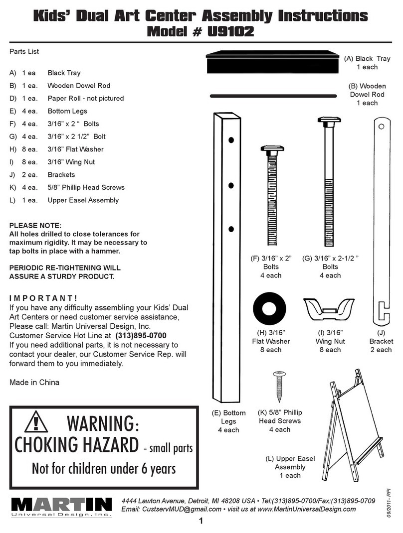
Martin Universal Design U9102 User manual

Martin Universal Design

Martin Universal Design U9102 User manual

Martin Universal Design Ashley U-DS92ST User manual

Martin Universal Design

Martin Universal Design Ashley U-DS92ST User manual

Martin Universal Design U-DS90W User manual

Martin Universal Design

Martin Universal Design U-DS90W User manual

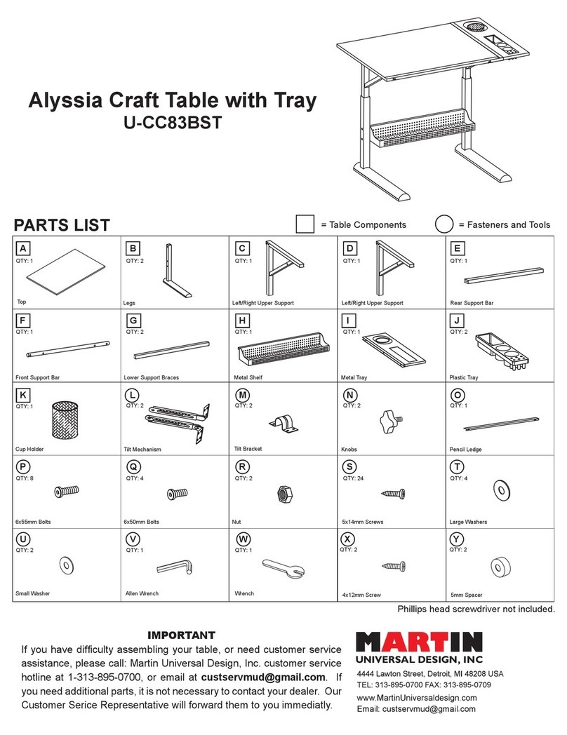
Martin Universal Design Alyssia Craft Table with Tray User manual

Martin Universal Design

Martin Universal Design Alyssia Craft Table with Tray User manual

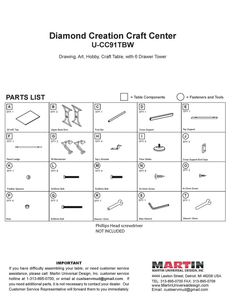
Martin Universal Design Creation Craft Center U-DS91TBW User manual

Martin Universal Design

Martin Universal Design Creation Craft Center U-DS91TBW User manual

Martin Universal Design STANFORD 91-1006 User manual

Martin Universal Design

Martin Universal Design STANFORD 91-1006 User manual

Martin Universal Design VESUVIO 91-8006 User manual
Martin Universal Design

Martin Universal Design VESUVIO 91-8006 User manual

Martin Universal Design AVANTI I User manual

Martin Universal Design

Martin Universal Design AVANTI I User manual

Martin Universal Design Diamond Creation Craft Center U-CC91TBW User manual

Martin Universal Design

Martin Universal Design Diamond Creation Craft Center U-CC91TBW User manual

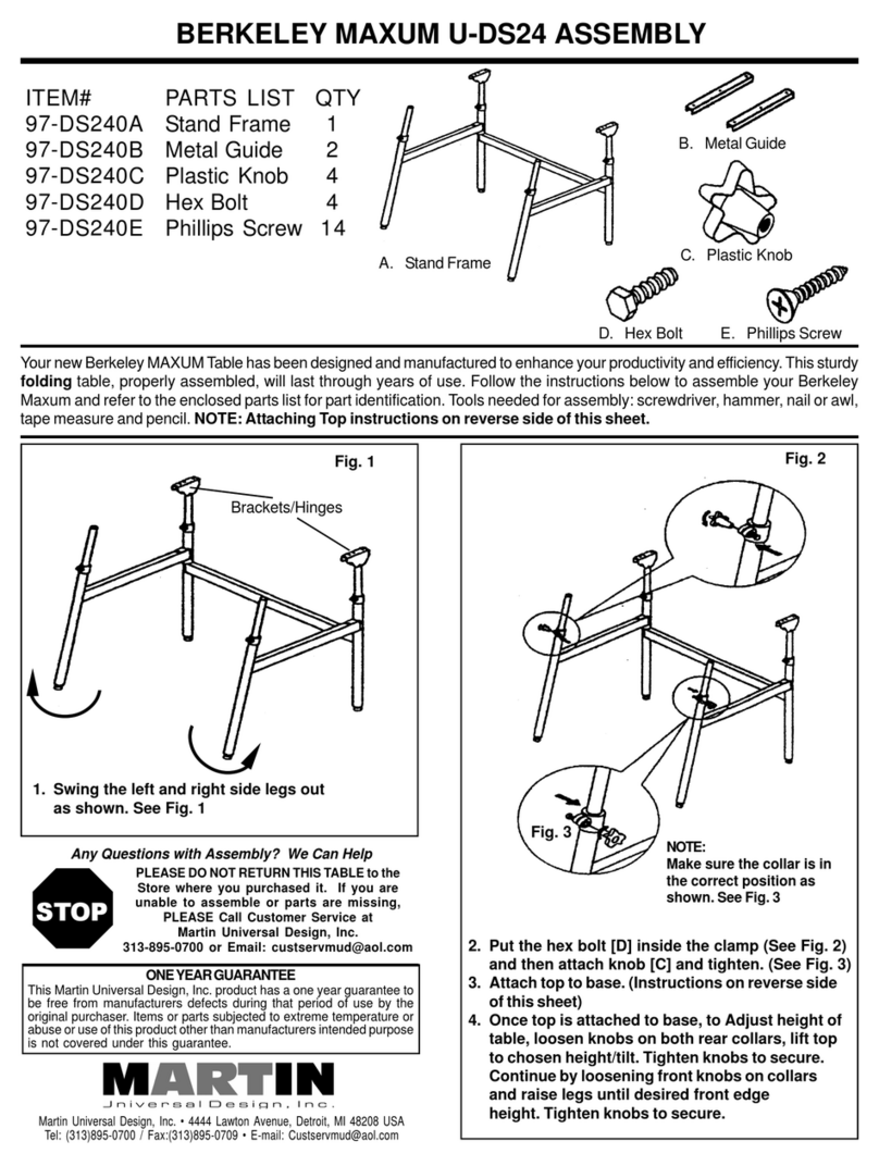
Martin Universal Design BERKELEY MAXUM U-DS24 User manual
Martin Universal Design

Martin Universal Design BERKELEY MAXUM U-DS24 User manual

Martin Universal Design Manchester User manual

Martin Universal Design

Martin Universal Design Manchester User manual

Martin Universal Design GRANDEUR 91-02606115 User manual

Martin Universal Design

Martin Universal Design GRANDEUR 91-02606115 User manual

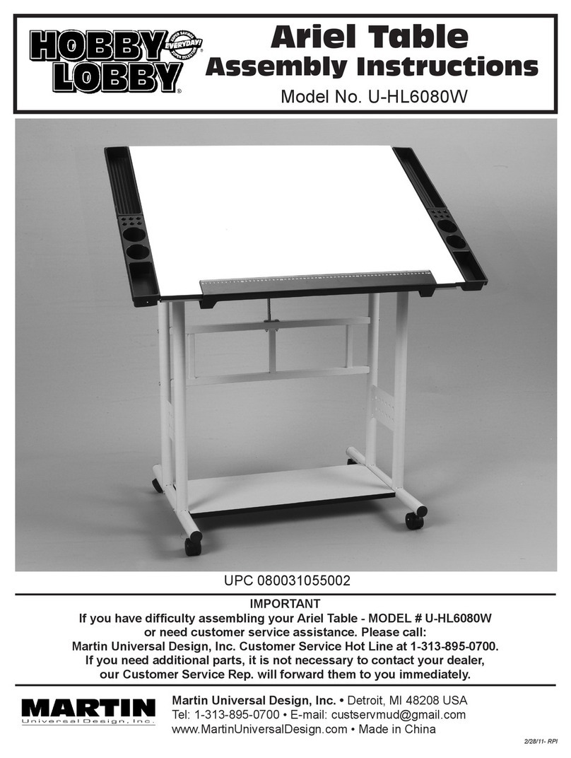
Martin Universal Design Hobby Lobby U-HL6080W User manual
Martin Universal Design

Martin Universal Design Hobby Lobby U-HL6080W User manual

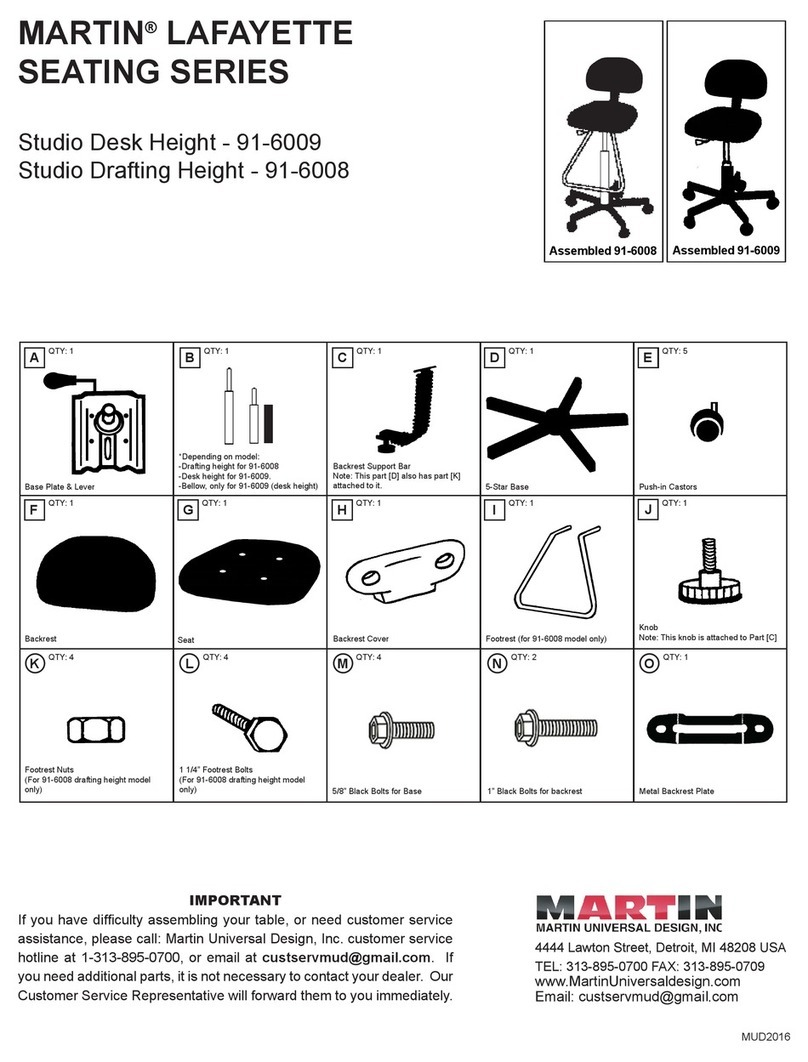
Martin Universal Design LAFAYETTE SEATING Series User manual

Martin Universal Design

Martin Universal Design LAFAYETTE SEATING Series User manual

Popular Indoor Furnishing manuals by other brands

Mocka Inca Bedside Assembly instructions

Mocka

Mocka Inca Bedside Assembly instructions

VonHaus 2500506 quick start guide

VonHaus

VonHaus 2500506 quick start guide

Furinno JAYA 21031 Assembly instruction

Furinno

Furinno JAYA 21031 Assembly instruction

MTM FLEX HEIGHT ADJUSTABLE TABLE BASE Assembly instructions

MTM

MTM FLEX HEIGHT ADJUSTABLE TABLE BASE Assembly instructions

Homelegance 9467BR-1 Assembling instructions

Homelegance

Homelegance 9467BR-1 Assembling instructions

Costway HW56765 Assembly instructions

Costway

Costway HW56765 Assembly instructions

Expert Manufacturing Princeton PN2972LF Disassembly instructions

Expert Manufacturing

Expert Manufacturing Princeton PN2972LF Disassembly instructions

Blumfeldt Burgos Round 10033579 Assembly instructions

Blumfeldt

Blumfeldt Burgos Round 10033579 Assembly instructions

fantastic furniture Carrington manual

fantastic furniture

fantastic furniture Carrington manual

Kidsaw Pilot's Work Station manual

Kidsaw

Kidsaw Pilot's Work Station manual

Möbelix ALMA OTMBK-2F Assembly instructions

Möbelix

Möbelix ALMA OTMBK-2F Assembly instructions

Cooper Lighting HALO DE600 Specifications

Cooper Lighting

Cooper Lighting HALO DE600 Specifications

ThunderDog TCD2 Assembly instructions

ThunderDog

ThunderDog TCD2 Assembly instructions

FANCII Maya manual

FANCII

FANCII Maya manual

Furinno 21027 Assembly instruction

Furinno

Furinno 21027 Assembly instruction

IKEA BEDDINGE BED STORAGE BOX Assembly instructions

IKEA

IKEA BEDDINGE BED STORAGE BOX Assembly instructions

KWC Faucet none maintenance

KWC

KWC Faucet none maintenance

Novogratz 1323015COM manual

Novogratz

Novogratz 1323015COM manual

manuals.online logo
manuals.online logoBrands
  • About & Mission
  • Contact us
  • Privacy Policy
  • Terms and Conditions

Copyright 2025 Manuals.Online. All Rights Reserved.