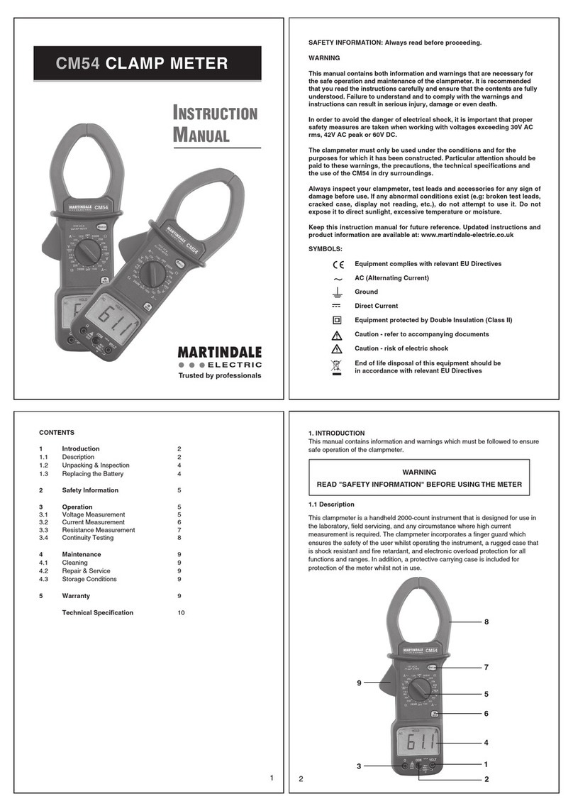
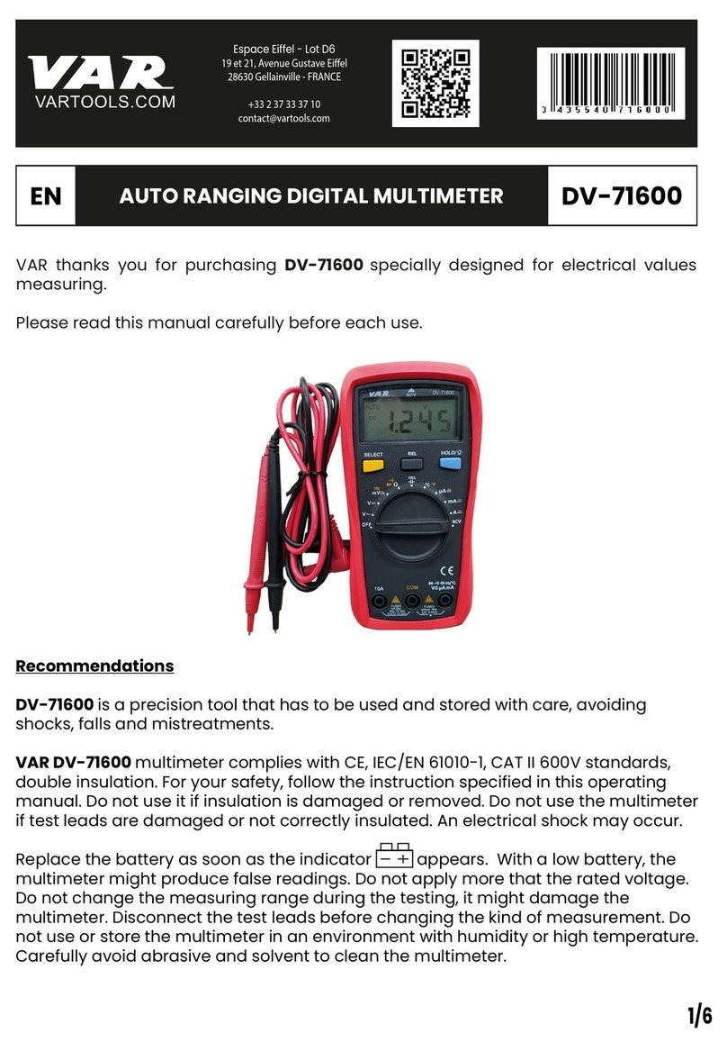
MARTINDALE AM5 User manual

resistance scale. If you cannot achieve
this, replace the battery with a new one
as follows:
1. Remove instrument from all circuits.
2. Remove the protective rubber holster
and open the battery case on the rear of
the instrument.
3. Loosen the 3 screws.
4. Replace the discharged battery with a
new battery (1.5V, AA, IEC LR6).
Respect correct polarity!
5. Close battery case and continue
measurements.
Fuse Replacement
If the fuse has blown due to current
range overload, please respect the
following references for fuse
replacement. Only use fuses with
specified current and voltage values,
switch-off characteristics and capacities.
1. Remove instrument from all circuits.
2. Remove the protective rubber holster
and open battery case on the rear of the
instrument.
3. Loosen the 3 screws.
4. Remove defective fuse.
5. Insert new fuse ensuring it is
positioned correctly (Fuse: 200mA /
250V, Fast Acting Martindale FUS-
F200). Using auxiliary fuses and short-
circuiting the fuse holders is prohibited
and can lead to instrument destruction
and serious personal injury.
Cleaning
If the instrument is dirty after usage, it is
advised to clean it by using a damp cloth
and mild household detergent. Never
use acid detergents or dissolvants. Do
not use until the unit has thoroughly
dried out.
Technical Data
Operating Temperature: 0-40°C, max.
75% RH.
Display: Analogue
Meter Movement: Wide 3 colour
mirrored scale 180µA movement.
Overvoltage Category: II max. 300V
Pollution Degree: 2
Battery: 1.5V, AA, IEC LR6
Fuse: 200mA / 250V Fast Acting
Dimensions: 120 x 60 x 30mm
Weight: 125g
Specifications are valid for 23°C ± 5°C,
max. 75% RH.
Resistance of Meter: 2kΩ/ V.
Martindale Electric Company Ltd
129 St Albans Road,
Watford,
WD17 1RA,
U.K.
Tel: 01923 441717
Fax: 01923 446900
Website: www.martindale-electric.co.uk
E-mail: [email protected]
Great care has been taken in the
completion of this instruction manual.
However, we cannot guarantee the
correctness of the data, figures or
drawings contained herein.
Subject to technical change without
notice.
© Martindale Electric Company Ltd
2001. Revised version: 06.
Introduction
The AM5 multimeter is a multi-function
instrument. The instrument has been
designed in accordance with the most
up-to-date safety regulations and
ensures safe, reliable measurement.
The compact AM5 multimeter is a useful
aid, for all standard measurements, to
the electrician on site, in industry or for
hobby electronics.
Analogue display.
DC & AC voltage measurement up to
500V.
DC current measurement up to 250mA.
Resistance measurement up to 2MΩ.
The AM5 is supplied with test leads.
When unpacking, check that the
instrument and the accessories are
complete and in good condition.
Symbols marked on the instrument:
Warns of potential danger,
observe the advice given in the
instruction manual.
Indicates a dangerously high
voltage.
Conformity symbol, the instrument
complies with the relevant
directives. It complies with the EMC
Directive (89/336/EEC) and the
standards EN 50081-1:1992 and EN
50082-1:1992. It also complies with the
Low Voltage Directive (73/23/EEC) and
EN 61010-1:1993.
Operator’s Safety
The instrument has left our factory in a
safe condition - to maintain this
condition, the user must pay attention to
the safety references contained in this
instruction manual.
WARNING This instruction manual
contains information and warnings
necessary for safe operation and
maintenance of the instrument. It is
recommended that you read and
understand this instruction manual
thoroughly prior to using the instrument:
failure to understand these instructions
and to comply with the warnings and
instructions, can result in serious injury
or damage.
WARNING In order to avoid electrical
shock, proper safety measures have to
be taken when working with voltages
exceeding 30V AC rms, 42V peak or
60V DC.
WARNING Prior to making any
measurement, ensure that test leads
and the test instrument are in perfect
condition. This measuring instrument
may only be used within the specified
ranges. The instrument may only be
opened for fuse or battery replacement
by competent persons.
Prior to opening the instrument, ensure
that it is switched off and disconnected
from any circuits.
Never measure current in circuits fused
Function
DCV
ACV
AccuracyRange
0 - 2.5 / 10 / 50 /
250 / 500V
0 - 10 / 50 / 500V
±5%
±5%
DCA 0 - 500µA /
10mA / 250mA ±5%
Ω0 - 20kΩ/ 2MΩ
(Rx10 / Rx 1k) ±5%
Battery
Test 1.5V (110mA) /
9V (9mA) ±10% (end of bad
& good line)
AM5 - Analogue
Multimeter
OPERATING INSTRUCTIONS

at more than 16A. Health & Safety
Guidance Note GS38 advises against
using this instrument on high energy
circuits due to the lack of fused leads.
To ensure correct functioning and long
life span, avoid leaving the instrument in
direct sunlight.
Operating Elements & Connections
1. Measurement Range Switch
2. Resistance-Zero-Adjustment
3. Analogue Display
4. Protective Rubber Holster
5. Test Leads with Probes
6. Battery casing on rear of instrument
Preparation & Safety Measures
WARNING Set range selection switch to
desired function prior to connecting test
probes to the UUT (Unit / circuit Under
Test).
Prior to switching to a new function or
measurement range, always disconnect
the measurement leads from the UUT.
Only use the multimeter in dry and clean
environments. Dirt and humidity lower
insulation resistances and can lead to
electric shocks in the case of higher
voltages.
Only use the multimeter within specified
measurement ranges.
Prior to and after instrument use, always
verify the instrument for correct
functioning (e.g. with a known voltage
source or a proving unit).
Ensure that measurement leads are in
perfect condition.
Only use fuses of the same type and
characteristics as originally supplied.
Short circuiting the fuse holders is
extremely dangerous.
Voltage Measurement
WARNING Never apply more than 500V
AC/DC at input sockets. Exceeding
these threshold values could lead to the
instrument being damaged or personnel
injuries.
WARNING Disconnect test probes from
the UUT prior to selecting a different
measurement range.
DC Voltage Measurement
1. Set measurement range switch (1) to
DC voltage measurement (DCV).
Always select the highest measurement
range for unknown voltages.
2. Connect test probes to UUT, select
lower measurement range as required,
until maximum resolution is achieved.
3. Read the voltage on the black scale.
AC Voltage Measurement
1. Set measurement range switch (1) to
AC voltage measurement (ACV). Always
select highest measurement range for
unknown voltages.
2. Connect test probes to UUT, select
lower measurement range as required,
until maximum resolution is achieved.
3. Read the voltage on the AC scale (for
10V range, read on the red 10V AC
scale).
Resistance Measurement
WARNING Prior to any measurement
ensure that the UUT is not live. If
required, carry out voltage measurement
for verification.
1. Set range selection switch (1) to Ω
range. Short two probes together and
adjust the 0 OHM ADJ (2) knob to set
the pointer to the “0” at the right end of
the resistance scale. If you cannot
achieve this, replace the battery with a
new one.
2. Connect test leads to UUT.
3. Read the resistance reading on the
OHM scale (green); use proper multiplier
to get the correct value (Rx10, Rx1k,
depending on the resistance range).
DC Current Measurement
WARNING Never measure in circuits
with more than 240V nominal voltage.
Do not attempt to read AC current. Do
not use on circuits where the current
may exceed 250mA DC.
1. Set range selection switch (1) to
DCmA.
2. In the case of unknown currents,
always select the 250mA current range
and switch to the lower measurement
range as required. Disconnect test leads
from UUT prior to changing
measurement ranges.
3. Connect multimeter in series with the
UUT and only switch on the UUT once
the multimeter is connected to the UUT.
4. Read the current reading on the
current scale.
Decibel Measurement
WARNING Never apply more than 500V
AC/DC at input sockets. Exceeding
these threshold values could lead to the
instrument being damaged or personnel
injuries.
WARNING Disconnect test probes from
the UUT prior to selecting a different
measurement range.
1. Set the selector switch to one of the
ACV ranges.
2. For 10V AC range, read dB reading
on the dB scale directly, but for other
ranges, calculate the reading using the
table below:
NOTE: For absolute dB measurement,
the circuit impedance must be 600Ω.
0dB = 1mW dissipated in a 600Ωload.
3. For a signal with a DC component,
insert a capacitor > 0.1µF between the
test probe and circuit under test.
Battery Check
1. Set selector switch to one of the
BATT positions.
2. Connect probes to the battery with the
red probe to the +ve terminal and the
black to the -ve terminal.
3. Read the GOOD/BAD (green and red)
scale.
Maintenance
When using the instrument in
compliance with the instruction manual
no special maintenance is required. Any
adjustments and repairs may only be
carried out by competent persons.
Calibration
To ensure accuracy and reliability of
measurement results, we recommend
you calibrate the instrument periodically.
Battery Replacement
Short the two probes together and adjust
the 0 OHM ADJ (2) knob to set the
pointer to the “0” at the right end of the
dB Range
ACV Range
Add Value
24 to 564 to 36-10 to 22
10V
0
50V
14
500V
34
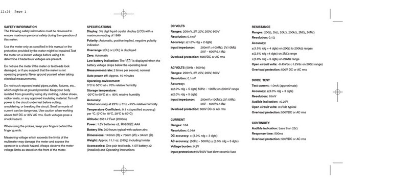
Table of contents
Other MARTINDALE Multimeter manuals

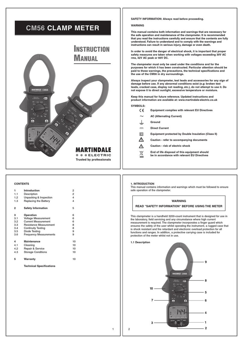
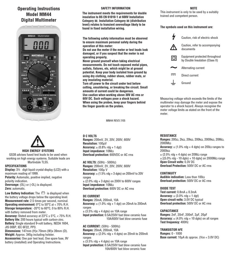
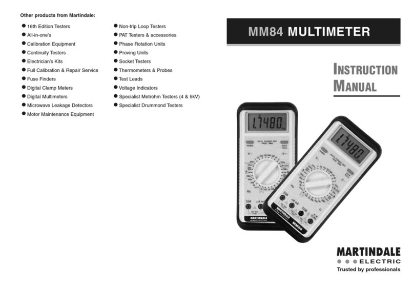
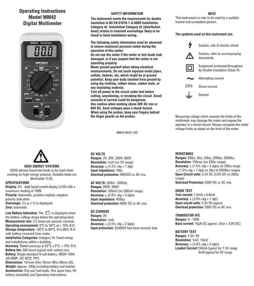
MARTINDALE
MARTINDALE MM65 User manual

MARTINDALE
MARTINDALE MM44 User manual

MARTINDALE
MARTINDALE CM56 User manual

MARTINDALE
MARTINDALE MM84 User manual

MARTINDALE
MARTINDALE CM57 User manual

MARTINDALE
MARTINDALE MM35 User manual

MARTINDALE
MARTINDALE MM42 User manual

MARTINDALE
MARTINDALE MM68 User manual

MARTINDALE
MARTINDALE MM39 User manual

MARTINDALE
MARTINDALE MM47 User manual

MARTINDALE
MARTINDALE MM34 User manual

MARTINDALE
MARTINDALE MM37 User manual

MARTINDALE
MARTINDALE CM54 User manual

MARTINDALE
MARTINDALE VERITEST 2240 User manual

MARTINDALE
MARTINDALE MM64 User manual

MARTINDALE
MARTINDALE MM84 User manual

MARTINDALE
MARTINDALE MM94 User manual

MARTINDALE
MARTINDALE MM45 User manual