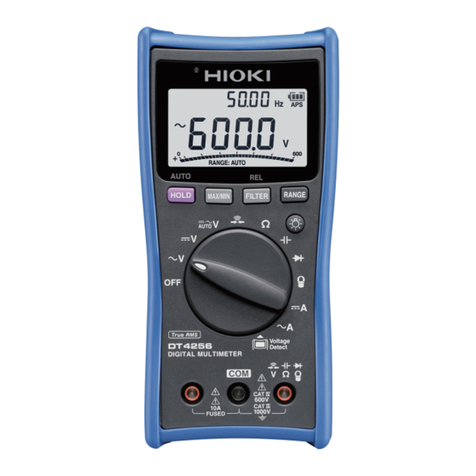
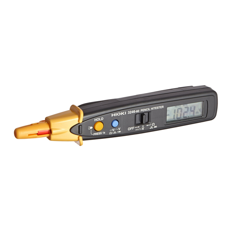
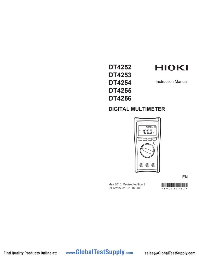
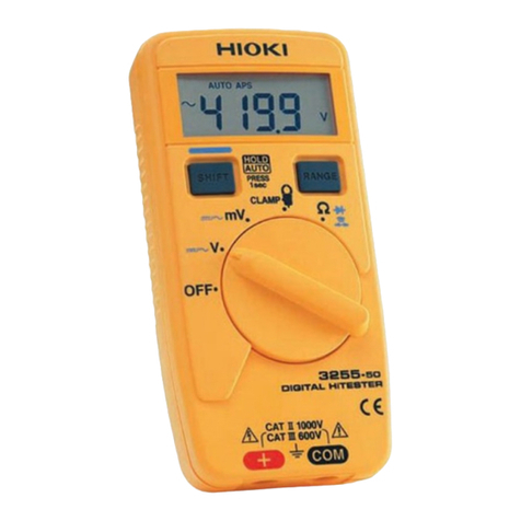
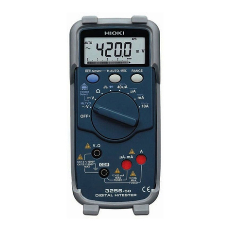
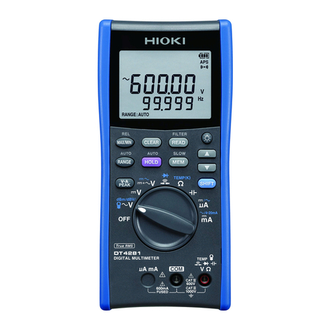
Hioki DT4200 Series User manual

DIGITAL MULTIMETER DT4200 Series
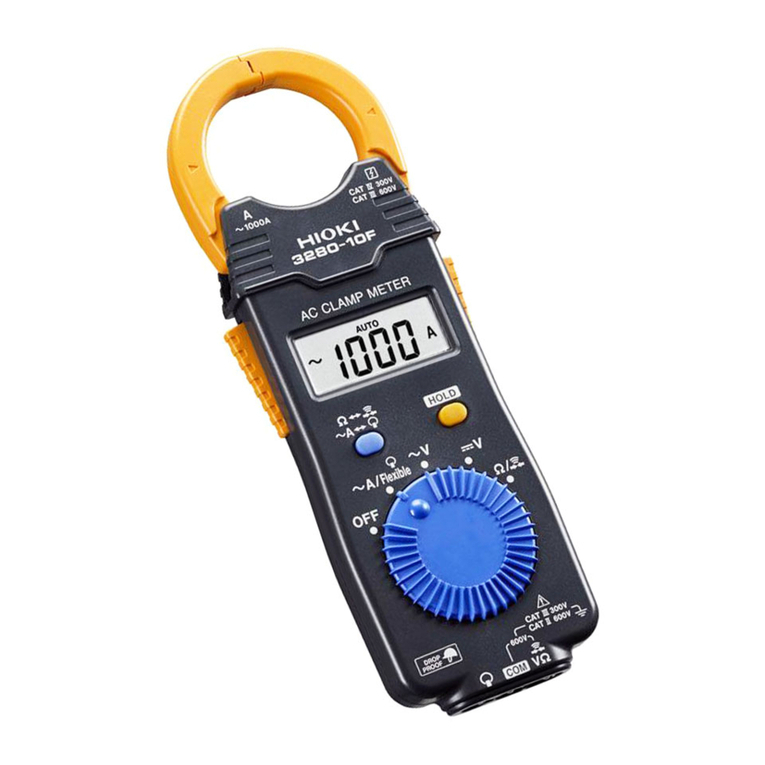
New wireless “Middle Model” DT4261 between the Standard
and High-end models of the DT4200 lineup!

2
Bluetooth®wireless technology support for recording
and managing measurement data
Now joined by the DT4261!
Bluetooth®communication with Z3210 attached to DT4261
Manage measurement data using GENNECT Cross
Install the Wireless Adapter Z3210 to the DT4261 to enable Bluetooth®communications.
With the Z3210, you can transfer data directly to an Excel® le or pair the instrument with GENNECT Cross.
Pair the DT4261 built in with Bluetooth® wireless technology with the free GENNECT Cross
mobile app to further data management, processing and report exporting on your mobile device.
GENNECT
Cross
Z3210
For more details
Attach to enable Bluetooth®wireless technology
Transport to GENNECT Cross
Transport to the Excel® le
GENNECT
Cross
For more details
• Save data and create reports
right on the App
• Share data via
cloud services or E-mail
CloudMail
Screen 1 Screen 2 Screen 3
Take a picture of
the test location and
map measured
values on it
Troubleshoot with
simple harmonic
analysis in the eld
View and verify
waveforms on your
mobile device like on
an oscilloscope
Transfer data to
a tablet wirelessly

3
The DT4255’s voltage input terminals incorporate a
protective fuse so that contamination of the instrument’s
internal components with iron powder or other particulate
matter will not result in an internal short-circuit. The fuse
can be replaced easily on site.
The DT4281, DT4282 and DT4261 use terminal shutters to
keep probes from being inserted into the wrong inlets. The
shutters block whichever terminal is not being used based
on the selected measurement function.
To prevent an accident, a warning function immediately
noties the operator if the DMM receives excessively high
input.
The DT4281, DT4261, DT4253, DT4255 and DT4256
eliminate the root cause of such accidents by providing
clamp-on sensor-based current measurement functionality
instead of using conventional probes.
*Red screen available on high-end models and DT4261, DT4223, DT4224 only.
A range: Only the A and COM terminal inlets open.
V range: Only the V and COM terminal inlets open.
Prevent unavoidable debris from shorting the
measurement target and causing an accident.
Mistakenly tripped circuit breakers and arcs due to careless input of voltage to the resistance range
can be extremely hazardous.
Wrong insertion
may lead to short-circuits.
Continued high input may result in major
accidents such as re.
Mistakenly measuring voltage using the
current range may lead to a short-circuit.
Hazard
1
Erroneous circuit-breaker activation Arcing and sparks
Switch to resistance range
Switch measurement circuit
Because changing the measurement range also changes the
measurement circuit, mistakenly inputting voltage with the instrument
set to the resistance range will cause a large current to ow to the
device, leading to hazards such as tripped circuit breakers and arcing.
The measurement circuit is switched after the instrument detects
resistance, continuity, capacitance, or diode input. Even if you
mistakenly input voltage with the instrument set to the resistance range,
the high input impedance will limit the current owing to the instrument
to 1.5 mA or less to prevent potential hazards.
Detect input
Resistance range
measurement circuit Input-based switching of the
measurement circuit
Voltage range
measurement circuit Resistance range
measurement circuit
The DT4223 and DT4224 feature a new proprietary function that prevents
accidents resulting from breakers that mistakenly trip due to incorrect input
Conventional digital multimeters DT4223 / DT4224 Digital Multimeter
High input impedance
1.5 MΩ
or greater
High input impedance
1.5 MΩ
or greater
Low input impedance
Constant current generation
circuit for measurement
Low input impedance
Constant current generation
circuit for measurement
Safe testers that protect workers
from dangerous accidents
Hazard
2
Hazard
4
Hazard
3
Hazard
5

4
To ensure operators’ ability to use measuring instruments safely,
IEC 61010 classies the locations in which instruments are used
into a series of safety-based measurement categories (ranging
from CAT II to CAT IV). Using an instrument that does not satisfy
the required safety level can lead to an electrical accident.
All development, design, and manufacturing processes for
almost all Hioki digital multimeters are carried out at our
Head Ofce in Nagano Prefecture. Some of the industry’s
most advanced technological capabilities enable us to
deliver products of the highest possible quality.
Safe measurement requires use of an instrument
that suits the measurement location.
Designed and manufactured in Japan to
ensure high quality and guaranteed with a
3-year warranty for peace of mind
CAT IV 600 V
Measurement category
suited to the location of use
Terminal-to-ground voltage
High-end models CAT III 1000 V / CAT IV 600 V
Standard models CAT III 1000 V / CAT IV 600 V
Pocket models CAT III 600 V / CAT IV 300 V
Service wires
Distribution
panel
L1
N
L2
Line voltage:
100 V
TV: 100 V
100V
100V
Air conditioner: 200 V
Line voltage:
200 V
Line voltage:
100 V
Pole-mounted
transformer
Electric
wires
Ground (0 V)
Measurement categories
Terminal-to-ground voltage
Buried wires
Transformer
Outlet Outlet
Service
connection
Service
wires
Power meter Distribution
panel
Distribution
panel
Fixed
equipment

5
Field-Proven Strength and Usability
DT4200 series
Robust design capable of withstanding a drop from a
height of 1 m onto concrete
Fast, accurate measurement of the output voltage on the
secondary side of an inverter
Outstanding viewing angle so display is easy to read at
an angle or even in a dim location
Hand-free and easy to use New L9300 test leads with integrated cap*
Extensive selection of probe tips that you can choose based on the measurement location, improving ease of measurement
True RMS measurement for accurate measurement of
even distorted current waveforms
Rotary switch that’s easy to operate even when
wearing gloves
The DT series can accurately measure the voltage on the secondary
side of an inverter, just like a power meter. Its low-pass lter rejects
harmonic components so that the fundamental wave can be
isolated and accurately measured.
Current waveforms are often distorted, causing the average-value
and true RMS measurement methods to yield different results. To
obtain accurate readings, RMS measurement is indispensable.
Preventing instrument failure by keeping out dust
With screw terminals In deep-set locations
that can’t be reached
with other probes
For clamping around the
target busbar
To test our products’ ability to
withstand mechanical shock,
we repeatedly drop them from a
height of at least 1 m until they
break. This drop-testing regime
leads to more robust products
by fostering a series of design
improvements.
If dust gets into the instrument’s
enclosure, it can cause the device to
fail. Since dust can get into the
instrument especially easily through
the gap around the rotary switch, the
DT4200 series incorporates a
dust-proof part known as an O-ring
where the rotary switch is mounted to
improve the device’s dust resistance.
It’s hard to carry out work tasks smoothly when
you’re juggling a measuring instrument, probes,
recording paper, and other supplies. Field concerns
like these are resolved by the DT4200’s magnetic
strap, auto-hold function*, and ability to save results
in its internal memory. These capabilities boost work
efciency and help reduce work times.
*The auto-hold function is available exclusively in high-
end, standard models and DT4261,DT4223,DT4224.
The ability to save results in internal memory is available
exclusively in high-end models.
*Standard accessory for DT4261
*Compatible probe tips vary with the DMM model. Please
see page 16. The optional Connection Cable L4930 is
required in order to use the probes shown at the left.
The DT4200 series features a display
with a wide viewing angle and a
backlight function so that it’s easy to
read, even when you can’t view the
screen from the front or when making
measurements in a dim location.
With the DT4200, you can choose the
probe type that best suits your
measurement location, making it possible
to measure in areas that can’t be reached
with conventional probes and busbars that
you wish to clamp between probes.
With low-pass lter off With low-pass lter on
True RMS method
measured value
Average-value method
measured value
Drop tester
The DT4200’s rotary switch is
designed to be easy to turn even
when wearing thick work gloves, for
example while working in
hazardous measurement locations
or harsh conditions.
Test leads L9300 now incorporate
integrated caps. The design lets
you change the measurement
category simply by sliding the test
lead’s protective nger guard.
As an added bonus, you no longer
have to worry about losing caps!
UNLOCK
CAT Ⅳ 600 V
CAT Ⅲ 1000 V
CAT Ⅱ 1000 V
LOCK
SLIDE
6
For electrical
work in the eld
For laboratory and
research use
DT4281 DT4282
Designed for maximum safety in the
eld when measuring current with
clamp-on sensors.
Designed for use in laboratories and
R&D applications where you wish to
measure a wide variety of parameters.
AC clamp-on measurement
Frequency
Resistance Continuity check
Temperature Diode test
Capacitance Conductance
AC/DC automatic detection
Voltage detection function
AC clamp-on measurement
Frequency
Resistance Continuity check
Temperature Diode test
Capacitance Conductance
AC/DC automatic detection
Voltage detection function
DC voltage
60.000 mV to 1000.0 V
AC voltage
60.000 mV to 1000.0 V
DC + AC voltage
6.000 V to 1000.0 V
DC current
600.00 μA to 600.00 mA
AC current
600.00 μA to 600.00 mA
DC voltage
60.000 mV to 1000.0 V
AC voltage
60.000 mV to 1000.0 V
DC + AC voltage
6.000 V to 1000.0 V
DC current
600.00 μA to 10.000 A
AC current
600.00 μA to 10.000 A
High-end models
Featuring high accuracy, extensive additional functionality,
and a broad range of measurement parameters
DC V typical accuracy: ±0.025% rdg. ±2 dgt.
Measurement categories: CAT III (1000 V), CAT IV (600 V)
Supported measurement parameter Supported measurement parameter (with model-specic variations) Unsupported measurement parameter
*The range gures given indicate the instrument’s measurement ranges (not the range of measurable values).

7
Functions and Features
Display refresh rate
Relative display
Maximum/minimum
value display
Decibel conversion
Magnetic strap frees both hands
for work
Measure output voltage on the
secondary sides of inverters
Measure very low currents used by
gas-burning devices
Manage measurement data on a
computer
Percentage display for
instrumentation signal measurement
Automatically hold display values
and save results with one touch to
the DMM’s internal memory
Ripple voltage conrmation of DC
charging systems
Intuitive notication of continuity check
results and excessively high input with
a red screen backlight and beep
Peak value measurement / DC + AC voltage
measurement
DC μA range
4 to 20 mA / 0 to 20 mA percentage-
equivalent display
By using the magnetic strap to secure the
instrument to the wall, you can free both
hands so that you can more easily record
measured values, signicantly boosting work
efciency.
Accurately measure the fundamental wave
alone by eliminating harmonic components with
the DMM’s low-pass lter function.
High-end models provide a DC 600.00 μA
range for measuring burner ame currents.
Measurement results can be downloaded to
a computer via a USB connection. Once
downloaded, you can save them as a le
(text format) or display them as a graph
using the desired interval. Results can also
be sent in real time while measurement is
ongoing.
You can check percentage-equivalent
values.
*The computer and multimeter are electrically
isolated by means of optical communications so
that data can be sent with peace of mind.
The display is automatically held once the
measured value stabilizes. You can save
measurement results to the instrument’s
internal memory simply by pressing the
MEM key, making it easy to read and record
values during inspection work.
High-end models can detect ripple voltage
with a superposed DC signal.
High-end models notify the operator of continuity
check results and excessively high input with a
red screen backlight and beep, making it
possible to check measurement results intuitively.
Change the display
refresh speed to
stabilize the display
when performing
measurement
characterized by a high
level of variability.
View relative values
using the display value
before the relative
function was enabled as
the reference.
Check the maximum and
minimum measured
values shown on the
display after pressing
the MAX/MIN button.
Convert the results of AC
voltage measurement to a
decibel value relative to a
reference value and
display the results (dbm/
dbv).
Input
waveform
114.1 V 85.9 V 100 V
100.49 V
DC + AC measurement*
114.10 V+Peak measurement
85.90 V-Peak measurement
Using the magnetic strap (option)
Using the Communication Package DT4900-01 (option)
Temperature
Pressure
Flow rate Transducer
Continuous state
Excessively high input
With low-pass lter off With low-pass lter on
Fundamental component
Harmonic component
++
0 V 0 V *DC + AC value = (AC)2+ (DC)2
√
Output 1 Display
4 mA 0%
20 mA 100%
Output 2 Display
4 mA 0%
20 mA 100%
Fundamental component
Harmonic component
++
Burner Flame sensor
rod
Insulator
Control
board

8
GENNECT
Cross
Wireless communication is
supported in combination with
the wireless adapter Z3210 (sold
separately). In addition to working
with the free "GENNECT Cross"
application, the Excel® direct
input function can also be used.
The DT4261-90, a set of DT4261
and Z3210, is also available. It is
more economical than purchasing
the DT4261 and Z3210 separately,
and allows you to build a wireless
communication environment with one
purchase.
WIRELESS ADAPTER
Z3210
Easily go wireless and manage
your data digitally
DT4261-90
(Z3210 set product)
When Z3210 is installed
Middle model
Supports wireless communication to
increase work efciency
DC V typical accuracy: ±0.15% rdg. ±2 dgt.
Measurement categories: CAT III (1000 V), CAT IV (600 V)
Multi-functional, for
on-site maintenance
DT4261
Go wireless with the Z3210!
For trouble analysis in the eld.
AC clamp-on measurement
Frequency
Resistance Continuity check
Temperature Diode test
Capacitance Conductance
AC/DC automatic detection
Voltage detection function
DC voltage
600.0 mV to 1000 V
AC voltage
6.000 V to 1000 V
DC + AC voltage
6.000 V to 1000 V
DC current
600.0 mA to 10.00 A
AC current
600.0 mA to 10.00 A
Supported measurement parameter Unsupported measurement parameter
*The range gures given indicate the instrument’s measurement ranges. Not the range of measurable values. Please see page 16 for details.

9
Terminal shutter closes on unused
terminals depending on the mea-
surement function
Prevents incorrect current measure-
ment with the Fuse Check function
When combined with GENNECT Cross, the DT4261
you can perform simple harmonic analysis. Appli-
cations include harmonic measurement of power
conditioners for solar systems and problem analysis
of power supply systems.
The wireless adapter Z3210 (sold separately)
comes standard with an Excel®direct input function.
It enables direct transfer and input of measure-
ment data to templates created in Excel®leading to
increased work efciency in the eld.
Problems that can be caused by harmonics
•
Equipment burn-out and destruction due to overheating
• Malfunctions of power control devices
• Reduced service life and efciency for power devices
Troubleshoot in the eld
Improve work efciency!
Labor-saving measurement with
digitalization
UNLOCK
CAT Ⅳ 600 V
CAT Ⅲ 1000 V
CAT Ⅱ 1000 V
LOCK
SLIDE
Link with GENNECT Cross
Excel®Direct Input Function
Functions and Features
AC contacts
DC contacts
The DT4261’s terminal shutters are linked to
the instrument’s rotary switch. They block
access to test lead terminals that aren’t being
used, making it physically impossible to
insert a lead into the wrong terminal.
When switching from the clamp function to
the current function, a fuse disconnection
check is automatically performed.
This allows the user to know if the fuse is
broken before current measurement, which
prevents erroneous measurement.
Automatic switching of measurement
in locations where AC and DC
voltages are mixed
When making measurements in locations
with both AC and DC voltages, automatic
switching eliminates the need to operate the
rotary switch and helps prevent
measurement mistakes.
Manage measurement data on a computer
Measurement results can be downloaded to
a computer via a USB connection. Once
downloaded, you can save them as a le
(text format) or display them as a graph using
the desired interval. Results can also be sent
in real time while measurement is ongoing.
Using the Communication Package DT4900-01 (sold separately)
Free up hands for work with the magnetic
strap* and auto-hold function
Test leads with an integrated cap
for greater convenience and safety
By using the magnetic strap to secure the
instrument to the wall and the auto-hold
function to automatically stop display values,
you can free your hands, making it easier to
record measured values and signicantly
boosting work efciency.
The L9300 test lead with an integrated cap is
included as a standard. The nger guard can
be easily slid to switch between measurement
categories without worrying about losing the
cap.
*The Magnetic Strap is sold separately

10
AC clamp-on
measurement Frequency
Resistance
Continuity check
Temperature Diode test
Capacitance Conductance
AC/DC automatic
detection
Voltage detection
function
DC voltage
600.0 mV to 1000 V
AC voltage
6.000 V to 1000 V
DC + AC voltage
DT4281/4282 only
DC current
6.000 A to 10.00 A
AC current
6.000 A to 10.00 A
AC clamp-on
measurement Frequency
Resistance
Continuity check
Temperature Diode test
Capacitance Conductance
AC/DC automatic
detection
Voltage detection
function
DC voltage
600.0 mV to 1000 V
AC voltage
6.000 V to 1000 V
DC + AC voltage
DT4281/4282 only
DC current
60.00 mA to 10.00 A
AC current
600.0 mA to 10.00 A
AC clamp-on
measurement Frequency
Resistance
Continuity check
Temperature Diode test
Capacitance Conductance
AC/DC automatic
detection
Voltage detection
function
DC voltage
600.0 mV to 1000 V
AC voltage
6.000 V to 1000 V
DC + AC voltage
DT4281/4282 only
DC current
60.00 μA to 60.00 mA
AC current n/a
AC clamp-on
measurement Frequency
Resistance
Continuity check
Temperature Diode test
Capacitance Conductance
AC/DC automatic
detection
Voltage detection
function
DC voltage
600.0 mV to 1000 V
AC voltage
6.000 V to 1000 V
DC + AC voltage
DT4281/4282 only
DC current n/a
AC current n/a
AC clamp-on
measurement Frequency
Resistance
Continuity check
Temperature Diode test
Capacitance Conductance
AC/DC automatic
detection
Voltage detection
function
DC voltage
600.0 mV to 1500 V
AC voltage
6.000 V to 1000 V
DC + AC voltage
DT4281/4282 only
DC current n/a
AC current n/a
*According to Hioki research conducted in April 2015.
Featuring the world’s fastest DMM engine*
The DT4200 series features a dedicated IC that Hioki developed
in-house in order to deliver unprecedented measurement speed.
For laboratory
and
research use
DT4252
For laboratories and R&D
applications where you
wish to measure a wide
variety of parameters.
For instrumentation
4-20 mA
DT4253
Measure
instrumentation, air-
conditioning equipment,
and gas-burning
devices.
Voltage
measurement
only model
DT4254
Measure no-load
voltage of photovoltaic
modules
at up to 1700 V DC.*
For electrical
work in the eld
DT4255
Designed for
maximum safety with
voltage measurement
terminals that are
protected by a fuse.
Multifunction
model
DT4256
Delivers maximum
functionality for use
in a wide range of
settings.
Standard models
Introducing a line of eld-optimized instruments that
can be chosen based on the application at hand
DC V typical accuracy: ±0.3% rdg. ±3 dgt.
Measurement categories: CAT III (1000 V), CAT IV (600 V)
Supported measurement parameter Supported measurement parameter (with model-specic variations) Unsupported measurement parameter
The range gures given indicate the instrument’s measurement ranges (not the range of measurable values).
*Your instrument can be used to measure voltages in excess of 1000 V DC if and only if both of the following conditions are satised:
1. The circuit under measurement is isolated from the commercial power grid. 2. The circuit under measurement is isolated from ground.

11
A: 0.63 A/1000 V fuse
B: Circuit current-limiting resistor ( 5Ω )
COM
BA
+
Tester
circuitry
Protective
circuit
Fuse capacity:
AC: 50 kA
DC: 30 kA
0 V 0 V
Burner Flame
sensor rod
Insulator
Control
board
Values are converted
to percentages and
displayed.
Output Display
4 mA 0%
20 mA 100%
AC contacts
DC contacts
Magnetic strap and auto-hold
function free up hands for easier
work
Automatic switching of
measurement in locations where
AC and DC voltages are mixed
Use a computer in the eld to save
and check measured values
By using the magnetic strap to secure the
instrument to the wall and the auto-hold
function to automatically stop display values,
you can free your hands, making it easier to
record measured values and signicantly
boosting work efciency.
When making measurements in locations
with both AC and DC voltages, automatic
switching eliminates the need to operate the
rotary switch and helps prevent
measurement mistakes.
Measured values can be displayed in real
time on a computer, and displayed values
can be saved to a le (text format) or graphed
at a user-specied interval.
*The computer and multimeter are electrically
isolated by means of optical communications so
that data can be sent with peace of mind.
Using the magnetic strap (option) AC/DC voltage automatic detection
(DT4253,DT4254, DT4255, DT4256 only)
With the Communication Package DT4900-01
(option)
Measure output voltage on the
secondary sides of inverters
Percentage display for
instrumentation signal measurement
Thorough prevention of short-
circuit accidents
Test no-load voltage at megasolar
installations
Polarity detection and notication
1700 V DC measurement (DT4254 only)
4 to 20 mA percentage-equivalent display (DT4253 only)
Voltage measurement terminal fuse (DT4255 only)
Accurately measure the fundamental wave by
eliminating harmonic components with the
DMM’s low-pass lter function.
The standard models’ dual display function
lets you to simultaneously check measured
values and percentage-equivalent values at
a glance.
When using the resistance measurement function, a protective circuit
functions to prevent a short-circuit accident in the event of erroneous
operation such improperly supplying voltage input. Even if a
short-circuit occurs inside the tester, a current-limiting resistor will limit
any short-circuit current while a fast-blow fuse quickly and reliably
disconnects the tester circuitry, preventing a short-circuit accident.
Model DT4254 can measure DC voltages up
to 1700 V, enabling you to make no-load
voltage inspections of megasolar
installations.*
Certain standard models can detect a load
voltage in excess of -10 V and notify the
operator with a red LED and beep.
(DT4254,DT4255, DT4256 only)
Temperature
Pressure
Flow rate Transducer
With low-pass lter off With low-pass lter on
Fundamental component
Harmonic component
++
Fundamental component
Harmonic component
++
Measure very low currents used by
gas-burning devices
Intuitive notication of continuity
check results and excessively high
input with a red LED and beep
DC μA range (DT4253 only)
Model DT4253 provides a DC 60.00 μA
range for measuring burner ame currents.
Standard models notify the operator of continuity
check results and excessively high input with a
red LED and beep, making it possible to check
measurement results intuitively.
Continuous state
Excessively high input
*Your instrument can be used to measure voltages in excess of 1000 V DC if and only if both of the following conditions are satised:
1. The circuit under measurement is isolated from the commercial power grid. 2. The circuit under measurement is isolated from ground.
Functions and Features

12
Circuit breaker
false trip
prevention built-in
AC clamp-on measurement
Frequency
Resistance Continuity check
Temperature Diode test
Capacitance Conductance
AC/DC automatic detection
Voltage detection function
DC voltage
600.0 mV to 600.0 V
AC voltage
6.000 V to 600.0 V
DC + AC voltage
DT4281/4282 only
DC current n/a
AC current n/a
AC clamp-on measurement
Frequency
Resistance Continuity check
Temperature Diode test
Capacitance Conductance
AC/DC automatic detection
Voltage detection function
DC voltage
600.0 mV to 600.0 V
AC voltage
6.000 V to 600.0 V
DC + AC voltage
DT4281/4282 only
DC current n/a
AC current n/a
AC clamp-on measurement
Frequency
Resistance Continuity check
Temperature Diode test
Capacitance Conductance
AC/DC automatic detection
Voltage detection function
DC voltage
600.0 mV to 600.0 V
AC voltage
6.000 V to 600.0 V
DC + AC voltage
DT4281/4282 only
DC current n/a
AC current n/a
AC clamp-on measurement
Frequency
Resistance Continuity check
Temperature Diode test
Capacitance Conductance
AC/DC automatic detection
Voltage detection function
DC voltage
600.0 mV to 600.0 V
AC voltage
6.000 V to 600.0 V
DC + AC voltage
DT4281/4282 only
DC current n/a
AC current n/a
*According to Hioki research conducted in April 2015.
Featuring the world’s fastest DMM engine*
The DT4200 series features a dedicated IC that Hioki developed
in-house in order to deliver unprecedented measurement speed.
Pocket models
Featuring a compact body for ergonomic hold
and a reliable, safe design
DC V typical accuracy: ±0.5% rdg. ±5 dgt.
Measurement categories: CAT III (600 V), CAT IV (300 V)
For electrical
work in the eld
DT4221
Delivering maximum eld safety
for workers whose principal use
is voltage measurement.
For electrical
work in the eld
DT4223
Delivering maximum eld safety
for workers whose principal use
is voltage measurement.
For multiple
applications
DT4222
For laboratories and R&D
applications to measure a wide
variety of parameters.
For multiple
applications
DT4224
For laboratories and R&D
applications to measure a wide
variety of parameters.
Supported measurement parameter Supported measurement parameter (with model-specic variations) Unsupported measurement parameter
*The range gures given indicate the instrument’s measurement ranges (not the range of measurable values).

13
Card HiTester 3244 During measurement
Beep
DT4221
Immediate display of
measurement results
Automatic switching of
measurement in locations where
AC and DC voltages are mixed
Detect voltage simply by holding
the instrument against a wire
AC/DC voltage automatic detection (DT4221, DT4223 only)
Voltage detection function
(DT4221, DT4223 only)
Compact and lightweight design
for outstanding ease of use
The small form factor ts in your hand
perfectly and is easily stowable, making it
convenient to transport to and from the eld
and boosting work efciency. The
lightweight design also ensures that pocket
models are easy to work with.
When making measurements in locations
with both AC and DC voltages, automatic
switching eliminates the need to operate the
rotary switch and helps prevent
measurement mistakes.
Easily detect voltage with the built-in sensor.
Results are communicated with a beep.
Safe enough for measuring
voltage at distribution panels and
service wires
Fast measurement for outstanding
ease of use
Intuitive notication of excessively
high input with ashing screen
The pocket digital multimeters notify the
operator of excessively high input by ashing
the screen, making it possible to check
measurement results intuitively.
Despite a compact body, the pocket models
can be used to measure voltage at
distribution panels and service wires in CAT
III (600 V), CAT IV (300 V) situations.
Measured values are displayed quickly to
facilitate quick testing. The difference is
clear when you compare the measurement
speed with that of the Hioki Card HiTESTER
3244-60.
AC contacts
DC contacts
New DT4223 and DT4224 feature circuit breaker false trip prevention
Prevent potential accidents during
incorrect input
The measurement circuit switches only after
detecting the appropriate signal.This way,
even if you mistakenly input voltage, accidents
due to tripped breakers or arcs will not
happen. (see page 2)
Warning function
noties you of incorrect input.
The instrument’s display ashes red to warn
you when voltage has been mistakenly input
while the instrument is set to the resistance
range.
LoZ icon identies switched
measurement circuit
When the instrument detects resistance,
continuity, capacitance, or diode input, the
LoZ icon is shown on the display, allowing
you to identify at a glance which
measurement circuit has been selected.
Functions and Features

14
DT4200 Series Basic Comparison
Glossary
DT4281 DT4282
DT4261 / DT4261-90*
1
DT4252 DT4253 DT4254 DT4255 DT4256 DT4221 DT4222 DT4223 DT4224
Basic Characteristics
True RMS
Yes Yes Yes Yes
DC V basic accuracy
±0.025% rdg. ±2 dgt. ±0.15% rdg. ±2 dgt. ±0.3% rdg. ±5 dgt. ±0.3% rdg. ±3 dgt. ±0.5% rdg. ±5 dgt.
Measurement items (Typical ranges are indicated; may not reect maximum or minimum measurable signal)
DC voltage 60 mV to 1000 V 600 mV to 1000 V 600 mV to 1000 V
600 mV to 1500 V*2
600 mV to 1000 V 600 mV to 600 V
AC voltage 60 mV to 1000 V 6 V to 1000 V 6 V to 1000 V 6 V to 600 V
DC V + AC V 6 V to 1000 V 6 V to 1000 V n/a n/a
DC A current
600 μA to 600 mA
600 μA to 10 A
60 mA to 10 A 6 A to 10 A
60 μA to 60 mA
n/a
60 mA to 10 A
n/a
AC A current
600 μA to 600 mA
600 μA to 10 A
60 mA to 10 A 6 A to 10 A n/a
600 mA to 10 A
n/a
AC clamp
10 A to 1000 A
n/a 10 A to 1000 A n/a
10 A to 1000 A
n/a
10 A to 1000 A 10 A to 1000 A
n/a
Resistance 60 Ω to 600 MΩ 60 Ω to 600 MΩ 600 Ω to 60 MΩ n/a 600 Ω to 60 MΩ n/a 600 Ω to 60 MΩ
Temperature -40℃ to 800℃ n/a n/a
-40℃ to 400℃
n/a n/a
Capacitance 1 nF to 100 mF 1 μF to 10 mF 1 μF to 10 mF n/a 1 μF to 10 mF n/a
1 μF to 10 mF
n/a
1 μF to 10 mF
Frequency 99 Hz to 500 kHz 99 Hz to 500 kHz 99 Hz to 99 kHz 99 Hz to 9.9 kHz
Continuity check Yes Yes Yes n/a Yes Yes
Diode check Yes Yes Yes n/a Yes n/a Yes n/a Yes
Conductance n/a Yes n/a n/a n/a
Voltage detection n/a n/a n/a Yes Yes n/a Yes n/a
Additional Functions
AUTO AC/DC V n/a Yes n/a Yes Yes n/a Yes n/a
Peak measurement
DC/AC DC/AC n/a n/a
Low-pass lter Analog lter
Cut-off: 630 Hz
Digital lter
Pass-band: 100/500 Hz
Digital lter
Pass-band: 100/500 Hz
Digital lter
Pass-band: 100/500 Hz
Display update setting
Yes n/a n/a n/a
Hold display value
AUTO/MANUAL AUTO/MANUAL AUTO/MANUAL MANUAL AUTO/MANUAL
Max/Min value display
Yes Yes Yes n/a
Relative display Yes n/a Yes Yes
Decibel conversion
Yes n/a n/a n/a
Percentage conversion display
Yes n/a n/a Yes n/a n/a n/a
DC voltage polarity check
n/a n/a n/a Yes n/a
Data storage
Capacity Max 400 data n/a n/a n/a
USB communication*3
Yes Yes Yes n/a
Bluetooth
®
communication*
4
n/a Yes n/a n/a
Operating time
Continuous operating time
Approx. 100 hours*5Approx. 130 hours*6Approx. 130 hours Approx. 40 hours Approx. 35 hours
Power supply
Alkaline (LR6) battery × 4/Manganese(R6P) battery × 4
Alkaline (LR6) battery × 3
Alkaline (LR03) battery × 4 Alkaline (LR03) battery × 1
Display
Back light Yes Yes Yes Yes
Dual display Yes Yes Yes n/a
Bar graph display n/a Yes Yes Yes
Safety
Safety standard categories
CAT Ⅲ 1000 V, CAT Ⅳ 600 V
CAT Ⅲ 1000 V, CAT Ⅳ 600 V CAT Ⅲ 600 V, CAT Ⅳ 300 V
Mis-insertion prevention shutters
Yes Yes n/a n/a
Circuit breaker false trip prevention
n/a n/a n/a n/a Ye s
Auto AC/DCV : Automatically detects and measures AC and DC voltage. | Peak measurement : After starting PEAK value measurement, check maximum and mini-
mum instantaneous voltage and current values. | Low-pass lter : Cuts high frequency content to provide stable numerical values for measurement. | Display update
setting : Reduces the display value update rate to stabilize measurements. | Hold display value : Manual: press the button to freeze the display. Auto: the display
freezes automatically when the measurement value is stable. | Max/Min value display : Pressing the MAX/MIN button displays the maximum and minimum displayed
measurement values. | Relative display : Pressing the REL button displays subsequent measurements as values relative to that displayed when the button was
pressed. | Decibel conversion : Displays AC voltage measurements converted to decibel values (dbm/dbv) | Percentage conversion display : Displays 4 to 20 mA (or
0 to 20 mA) signals converted to 0 to 100% values. For the DT4253, only 4 to 20 mA.
*1. Z3210 set product *2. Your instrument can be used to measure voltages in excess of 1000 V DC if and only if both of the following conditions are satised: 1. The circuit under measurement
is isolated from the commercial power grid. 2. The circuit under measurement is isolated from ground.
*3. Requires optional DT4900-01 Communication Package *4. Requires optional Z3210 wireless adapter *5. When using four AA alkaline batteries *6. When Z3210 is not installed

15
High-End DT4281 / DT4282
AC Voltage
Range Accuracy
20 Hz to 45 Hz 45 Hz to 65 Hz 65 HZ to 1 kHz 1 kHz to 10 kHz 10 kHz to 20 kHz 20 kHz to 100 kHz
60.000 mV
±1.3% rdg.
±60 dgt.
±0.4% rdg.
±40 dgt.
±0.% rdg.
±40 dgt.
±0.9% rdg.
±40 dgt.
±1.5% rdg.
±40 dgt.
±20% rdg. ±80 dgt.
600.00 mV
±8% rdg. ±80 dgt.
6.0000 V
±1% rdg.
±60 dgt.
±0.2% rdg.
±25 dgt.
±0.3% rdg.
±25 dgt.
±0.4% rdg.
±25 dgt.
±0.7% rdg.
±40 dgt.
±3.5% rdg.
±40 dgt.
60.000 V
Undened
600.00 V
Undened Undened
1000.0 V
DC V + AC V Measurement
Range Accuracy
20 Hz to 45 Hz 45 Hz to 65 Hz 65 HZ to 1 kHz 1 kHz to 10 kHz 10 kHz to 20 kHz 20 kHz to 100 kHz
6.0000 V ±1.2% rdg.
±65 dgt.
±0.3% rdg.
±30 dgt.
±0.4% rdg.
±30 dgt.
±0.4% rdg.
±30 dgt.
±1.5% rdg.
±45 dgt.
±3.5% rdg.
±125 dgt.
60.000 V
Undened
600.00 V
Undened Undened
1000.0 V ±0.4% rdg.
±45 dgt.
Input impedance 1 MΩ±4% // 100 pF or less
Crest factor 3 or less (1.5 or less for the 1000.0 V range)
Accuracy
specication range
5% or more of each range
With the lter ON, accuracy is dened only for frequencies
100 Hz or less. Furthermore, 2% rdg. is added.
DC A Measurement *1. DT4282 only
Range
Accuracy / Display update : slow
Accuracy / Display update : normal
Shunt Resistance
600.00 μA
±0.05% rdg. ±5 dgt.
±0.05% rdg. ±25 dgt. 101 Ω
6000.0 μA ±0.05% rdg. ±5 dgt.
60.000 mA ±0.05% rdg. ±25 dgt. 1 Ω
600.00 mA ±0.15% rdg. ±5 dgt. ±0.15% rdg. ±5 dgt.
6.0000 A*1
±0.2% rdg. ±5 dgt. ±0.2% rdg. ±25 dgt. 10m Ω
10.000 A*1 ±0.2% rdg. ±5 dgt.
AC A Measurement *1. DT4282 only
Range Accuracy
20 Hz to 45 Hz 45 Hz to 65 Hz 65 Hz to 1 kHz 1 kHz to 10 kHz 10 kHz to 20 kHz
600.00 μA ±1.0% rdg.
±20 dgt.
±0.6% rdg.
±20 dgt.
±0.6% rdg.
±20 dgt.
±2% rdg.
±20 dgt.
±4% rdg.
±20 dgt.
6000.0 μA ±1.0% rdg.
±5 dgt.
±0.6% rdg.
±5 dgt.
±0.6% rdg.
±5 dgt.
±2% rdg.
±5 dgt.
±4% rdg.
±5 dgt.
60.000 mA ±1.0% rdg.
±20 dgt.
±0.6% rdg.
±20 dgt.
±0.6% rdg.
±20 dgt.
±1% rdg.
±20 dgt.
±2% rdg.
±20 dgt.
600.00 mA ±1.0% rdg.
±5 dgt.
±0.6% rdg.
±5 dgt.
±0.6% rdg.
±5 dgt.
±1.5% rdg.
±10 dgt. Undened
6.0000 A*1 Undened ±0.8% rdg.
±20 dgt.
±0.8% rdg.
±20 dgt. Undened Undened
10.000 A*1 Undened ±0.8% rdg.
±5 dgt.
±0.8% rdg.
±5 dgt. Undened Undened
Shunt resistance μA Range 101 Ω, mA Range 1Ω, A Range 10 mΩ
Crest factor 3 or less (Note that it applies to 1/2 of the range.)
Accuracy specication range
Accuracy is not dened for measurements below 5% of range
Continuity Check
Range
Accuracy
Measurement Current
Open-terminal Voltage
600.0 Ω±0.5% rdg. ±5 dgt. 640 μA ±10% DC 2.5 V or less
Continuity threshold 20 Ω (default), 50 Ω, 100 Ω, 500 Ω
Capacitance Measurement
Range Accuracy
Measurement Current Open-circuit Voltage
1.000 nF ±1% rdg. ±20 dgt.
32 μA ±10% DC 2.5 V or less
10.00 nF
±1% rdg. ±5 dgt.
100.0 nF
1.000 μF
10.00 μF
±2% rdg. ±5 dgt. 680 μA ±20%
DC 3.1 V or less
100.0 μF
1.000 mF
DC 2.1 V or less10.00 mF
100.0 mF ±2% rdg. ±20 dgt.
Resistance Measurement
Range Accuracy
Measurement Current
Open-terminal Voltage
60.000 Ω ±0.3% rdg. ±20 dgt. 640 μA ±10%
DC 2.5 V or less
600.00 Ω ±0.03% rdg. ±10 dgt.
6.0000 kΩ
±0.03% rdg. ±2 dgt.
96 μA ±10%
60.000 kΩ 9.3 μA ±10%
600.00 kΩ 0.96 μA ±10%
6.0000 MΩ ±0.15% rdg. ±4 dgt.
96 nA ±10%
60.00 MΩ ±1.5% rdg. ±10 dgt.
600.0 MΩ ±3.0% rdg. ±20 dgt.
±8.0% rdg. ±20 dgt.
AC Clamp (AC Current) DT4281 only
Range Accuracy
40 Hz to 65 Hz 65 Hz to 1 kHz
10.00 A ±0.6% rdg. ±2 dgt. ±0.9% rdg. ±2 dgt.
20.00 A ±0.6% rdg. ±4 dgt. ±0.9% rdg. ±4 dgt.
50.00 A ±0.6% rdg. ±10 dgt. ±0.9% rdg. ±10 dgt.
100.0 A ±0.6% rdg. ±2 dgt. ±0.9% rdg. ±2 dgt.
200.0 A ±0.6% rdg. ±4 dgt. ±0.9% rdg. ±4 dgt.
500.0 A ±0.6% rdg. ±10 dgt. ±0.9% rdg. ±10 dgt.
1000 A ±0.6% rdg. ±2 dgt. ±0.9% rdg. ±2 dgt.
DC Voltage
Range Accuracy Input Impedance
60.000 mV ±0.2% rdg. ±25 dgt. 1 GΩ or more // 100 pF or less
600.00 mV ±0.025% rdg. ±5 dgt.
6.0000 V ±0.025% rdg. ±2 dgt. 11.0 MΩ ±2% // 100 pF or less
60.000 V 10.3 MΩ ±2% // 100 pF or less
600.00 V ±0.03% rdg. ±2 dgt. 10.2 MΩ ±2% // 100 pF or less
1000.0 V
The optional 9010-50, 9018-50, or 9132-50 CLAMP ON PROBE is used.
Accuracy does not include the error of the clamp-on probe.
Crest factor 3 or less
Accuracy is not dened for measurements below 15% of range
Conductance (nS) DT4282 only
Range Accuracy
Measurement Current Open-circuit Voltage
600.00 nS ±1.5% rdg. ±10 dgt. 96 nA ±10% DC 2.5 V or less
Accuracy is dened for humidity 60% RH or less. Accuracy is dened for the range
20nS or more. In the case of 300 nS or more, ±20 dgt. is added.
Diode Check
Range Accuracy
Measurement Current
Open-terminal Voltage
3.600 V ±0.1% rdg. ±5 dgt. 1.2 mA or less DC 4.5 V or less
Forward threshold
0.15 V, 0.5 V (default), 1 V, 1.5 V, 2 V, 2.5 V, 3 V
If the reading is lower than the threshold during the forward con-
nection, a buzzer sounds and the red backlight turns on.
Peak Measurement
(For AC V, DC V, DC+AC V, Clamp, DC μA, DC mA, DC A, AC μA, AC mA, AC A)
Main measurement
Signal width Accuracy
DC V 4 ms or more (single) ±2.0% rdg. ±40 dgt.
1 ms or more (repeated) ±2.0% rdg. ±100 dgt.
Other than
DC V
1 ms or more (single) ±2.0% rdg. ±40 dgt.
250 μs or more (repeated) ±2.0% rdg. ±100 dgt.
4, 8, 16, 32, 50, 75, 93, 110, 125, 135, 150, 200, 250, 300, 500, 600, 800, 900, 1000, 1200 Ω
(default: 600 Ω)
Temperature
Thermocouple Type Range Accuracy
K -40.0 to 800.0 °C (-40.0 to 1472.0°F)
±0.5% rdg. ±3°C (5.4°F)
The optional K Thermocouple DT4910 is used. Accuracy does not include the error of the K thermocouple.
Frequency (For AC V, DC + AC V, AC μA, AC mA, AC A)
Range Accuracy
99.999 Hz
±0.005% rdg. +3 dgt.
999.99 Hz
9.9999 kHz
99.999 kHz ±0.005% rdg. +3 dgt.
500.00 kHz
Decibel Conversion Measurement : Standard impedance (dBm)
Measurement range
0.5 Hz or more ([----] is displayed when frequency is less than 0.5 Hz)
Pulse width 1 μs or more (DUTY ratio is 50%)
With the lter ON, accuracy is dened only for frequencies 100 Hz or less. (For ACV, DC+ACV)
(Accuracy guaranteed for 1 year, post-adjustment accuracy guaranteed for 1 year)

16
General Specications
Durability
Drop proof Yes
Operating temperature and humidity*1
-15°C to 55°C
Storage temperature and humidity*2
-30°C to 60°C
Applicable standards
Safety: EN61010, EMC: EN61326; Waterproof and dustproof: IP40
Accessories
Safety
Maximum rated voltage
between
input terminals and ground
CAT Ⅲ 1000 V, CAT Ⅳ 600 V
Maximum rated voltage
between terminals Between the V and COM terminals: 1000 V DC/AC
Maximum rated current
between terminals
Between the mA and COM terminals: 600 mA DC/600 mA AC
Between the A and COM terminals: 10 A DC/10 A AC
TEST LEAD L9207-10, Instruction Manual, LR6 alkaline battery × 4
93W × 197H × 53D mm (3.66″W × 7.76″H × 2.09″D),
650 g (23 oz.) (including batteries)
Dimensions / Weight
*1. -15°C to 55°C (5°F to 131°F), Up to 40°C (104°F): at 80% RH or less (non-condensating),
40°C to 45°C (104°F to 113°F): at 60% RH or less (non-condensating),
45°C to 55°C (113°F to 131°F): at 50% RH or less (non-condensating)
*2. 80%RH or less (non-condensating)
High-End
Middle DT4261
(Accuracy guaranteed for 1 year, post-adjustment accuracy guaranteed for 1 year)
DC Voltage
Range Accuracy※1 Input Impedance
600.0 mV ±0.15% rdg. ±5 dgt. 11.3 MΩ ± 2.0 %
6.000 V
±0.15% rdg. ±2 dgt.60.00 V 10.4 MΩ ± 2.0 %
600.0 V 10.3 MΩ ± 1.5 %
1000 V ±0.15% rdg. ±5 dgt.
Resistance Measurement
Range Accuracy
Measurement Current
Open-terminal Voltage
600.0 Ω ±0.7% rdg. ±5 dgt. Approx. 200 μA
DC 2.0 V or less
6.000 kΩ
±0.7% rdg. ±3 dgt.
Approx. 100 μA
60.00 kΩ Approx. 10 μA
600.0 kΩ Approx. 1 μA
6.000 MΩ ±0.9% rdg. ±3 dgt. Approx. 100 nA
60.00 MΩ ±1.5% rdg. ±3 dgt. Approx. 10 nA
Accuracy guarantee condition After zero adjustment has been performed
Continuity Check
Range Accuracy
Measurement Current
Open-terminal Voltage
600.0 Ω ±0.7% rdg. ±5 dgt. Approx. 200 μA DC 2.0 V or less
Continuity ON threshold
Approx. 25 Ω or less (continuous buzzer sound, red backlight on)
Continuity OFF threshold
Approx. 245 Ω or more (buzzer sound off, red backlight off)
Diode Check
Range Accuracy
Measurement Current
Open-terminal Voltage
1.800 V ±0.5% rdg. ±5 dgt. Approx. 200 μA DC 2.0 V or less
Forward threshold Intermittent buzzer sound at 0.15 V to 1.8 V, continuous buzzer
sound at less than 0.15 V, red backlight on.
AC Clamp (AC Current)
Range Accuracy
40 Hz to 500 Hz 500 Hz to 1 kHz
10.00 A
±0.9% rdg. ±3 dgt. ±1.5% rdg. ±3 dgt.
20.00 A
50.0 A
100.0 A
200.0 A
500 A
1000 A
The optional 9010-50, 9018-50, or 9132-50 CLAMP ON PROBE is used.
Accuracy does not include the error of the clamp-on probe.
Crest factor 3 or less
Accuracy specication range
Minimum 1% of range; add ±5 dgt. when measuring at or below 5% of range
Capacitance Measurement
Range Accuracy Measurement Current
Open-terminal Voltage
1.000 μF
±1.9% rdg. ±5 dgt.
Approx. 10 n,100 n,1 μA
DC 2.0 V or less
10.00 μF Approx. 100 n,1 μ,10 μA
100.0 μF Approx. 1 μ,10 μ,100 μA
1.000 mF
Approx. 10 μ,100 μ,200 μA
10.00 mF ±5.0% rdg. ±20 dgt. Approx. 100 μ,200 μA
Frequency
Range Accuracy
99.99 Hz
±0.1% rdg. +1 dgt.
999.9 Hz
9.999 kHz
99.99 kHz (V AC Only)
AC Voltage
Range Accuracy Input Impedance
40 Hz to 500 Hz 500 Hz to 1 kHz
6.000 V
±0.9% rdg. ±3 dgt. ±1.5% rdg. ±3 dgt.
11.3 MΩ ± 2.0% // 100 pF or less
60.00 V
10.4 MΩ ± 2.0% // 100 pF or less
600.0 V
10.3 MΩ ± 1.5% // 100 pF or less
1000 V
DC A Measurement
Range Accuracy Input Impedance
600.0 mA
±0.5% rdg. ±3 dgt. 35 mΩ ±30%6.000 A
10.00 A
AC A Measurement
Range Accuracy Input Impedance
40 Hz to 500 Hz 500 H to 1 kHz
600.0 mA
±1.4% rdg. ±3 dgt. ±1.8% rdg. ±3 dgt. 35 mΩ ±30%6.000 A
10.00 A
Crest factor
3 at up to 4000 counts and reduces linearly to 2 at 6000 counts.
1000 V range only: 2 at up to 750 counts, linearly decreasing to
1.5 at 1000 counts.
Accuracy specication range
For ACV, minimum 1% of range; add ±5 dgt. when measuring at or below 5% of range.
Crest factor 3 at up to 4000 counts and reduces linearly to 2 at 6000 counts.
Accuracy specication range
For ACV, minimum 1% of range; add ±5 dgt. when measuring at or below 5% of range.
Accuracy specication range
Add ±2 dgt. when measuring at or below 5% of range.
*1. Add ±1 dgt. when measuring at or below 5% of range

17
General Specications
Accessories
Middle
Safety
Maximum rated voltage between
input terminals and ground
CAT Ⅲ 1000 V, CAT Ⅳ 600 V
Maximum rated voltage
between terminals Between the V and COM terminals: 1000 V DC/AC
Maximum rated current
between terminals Between the A and COM terminals: 10 A DC/10 A AC
Durability
Drop proof Yes
Operating temperature and humidity*1
-25℃ to 65℃
Storage temperature and humidity*2
-30℃ to 70℃
Applicable standards
Safety: EN61010, EMC: EN61326; Waterproof and dustproof: IP54*3
TEST LEAD L9300L9300, Instruction Manual, LR6 alkaline battery × 3
87W × 185H × 47D mm (3.43″W × 7.28″H × 1.85″D),
480 g (16.9 oz.) (including batteries)
*1: 80% RH or less at up to 40°C (non-condensating), linearly decreases from 80% RH at
40°C to 25% RH or less at 65°C (non-condensating)
*2: 80% RH or less (non-condensating) *3: Do not use in wet conditions.
Dimensions / Weight
DC Voltage *1. DT4252 only *2. DT4254 only
Range Accuracy Input Impedance
High precision
600 mV range*1 ±0.2% rdg. ±5 dgt. 10.2 MΩ ±1.5%
600.0 mV ±0.5% rdg. ±5 dgt. 11.2 MΩ ±2.0%
6.000 V
±0.3% rdg. ±3 dgt.*3
60.00 V 10.3 MΩ ±2.0%
600.0 V
10.2 MΩ ±1.5%1000 V
1500 V*2 ±0.3% rdg. ±3 dgt.*4
Resistance Measurement DT4252, DT4253, DT4255, DT4256 only
Range Accuracy
Measurement Current Open-terminal Voltage
600.0 Ω ±0.7% rdg. ±5 dgt. Approx. 200 μA
DC 1.8 V or less
6.000 kΩ
±0.7% rdg. ±3 dgt.*1
Approx. 100 μA
60.00 kΩ Approx. 10 μA
600.0 kΩ Approx. 1 μA
6.000 MΩ ±0.9% rdg. ±3 dgt.*1 Approx. 100 nA
60.00 MΩ ±1.5% rdg. ±3 dgt.*1 Approx. 10 nA
Accuracy guarantee condition After zero adjustment has been performed.
Continuity Check DT4252, DT4253, DT4255, DT4256 only
Range Accuracy
Measurement Current Open-terminal Voltage
600.0 Ω ±0.7% rdg. ±5 dgt. Approx. 200 μA DC1.8 V or less
Continuity ON threshold
Approx. 25 Ω or less (continuous buzzer sound, red LED lights)
Continuity OFF threshold
Approx. 245 Ω or more
Diode Check DT4252, DT4253, DT4255, DT4256 only
Range Accuracy
Measurement Current Open-terminal Voltage
1.500 V ±0.5% rdg. ±5 dgt.*1 Approx. 0.5 mA DC 5.0 V or less
Forward threshold
Buzzer sound intermittently at 0.15 V to 1.5 V, the red LED ashes.
AC Clamp (AC Current)
DT4253, DT4255, DT4256 only
Range Accuracy
40 Hz to 1 kHz
10.00 A
±0.9% rdg. ±3 dgt.
20.00 A
50.0 A
100.0 A
200.0 A
500 A
1000 A
The optional 9010-50, 9018-50, or 9132-50 CLAMP ON PROBE is used.
Accuracy does not include the error of the clamp-on probe.
Crest factor 3 or less
Accuracy specication range
Minimum 1% of range; add ±5 dgt. when measuring at or below 5% of range.
Capacitance Measurement
DT4252 ,DT4253, DT4255, DT4256 only
Range Accuracy
Measurement Current
Open-terminal Voltage
1.000 μF
±1.9% rdg. ±5 dgt.
Approx. 10 nA, 100 nA, 1 μA
DC 1.8 V or less
10.00 μF Approx. 100 nA , 1 μA , 10 μA
100.0 μF Approx. 1 μA , 10 μA , 100 μA
1.000 mF
Approx. 10 μA, 100 μA , 200 μA
10.00 mF ±5.0% rdg. ±20 dgt. Approx. 100 μA, 200 μA
Standard DT4252 / DT4253 / DT4254 / DT4255 / DT4256
*1. DT4255 : ±0.5% rdg. ±8 dgt.
*2. Your instrument can be used to measure voltages in excess of 1000 V DC if and only if both of the following conditions are satised:
1. The circuit under measurement is isolated from the commercial power grid. 2. The circuit under measurement is isolated from ground.
*3. DT4254,DT4255, DT4256 only, DT4252, DT4253 is ±5 dgt. *4. 0 to 1000 V, 1001 V to 1700 V: ±0.2% rdg. ±5 dgt.
AUTO V (Identication)
DT4253, DT4254, DT4255, DT4256 only
Range Accuracy Input Impedance
DC, 40 Hz to 500 Hz 500 Hz or more to 1 kHz
600.0 V ±2.0% rdg. ±3 dgt. ±4.0% rdg. ±3 dgt. 900 kΩ ±20%
1800 kΩ ±20%*1
AC Voltage
Range Accuracy Input Impedance
40 Hz to 500 Hz
500 Hz or more to 1 kHz
6.000 V
±0.9% rdg. ±3 dgt. ±1.8% rdg. ±3 dgt.
11.2 MΩ ±2.0% // 100 pF or less
60.00 V
10.3 MΩ ±2.0% // 100 or less
600.0 V
10.2 MΩ ±1.5% // 100 or less
1000 V
Crest factor 3 at up to 4000 counts and reduces linearly to 2 at 6000 counts.
Accuracy
specication range
For AC V, minimum 1% of range; add ±5 dgt. when measuring at or below 5% of range.
With the lter ON,the accuracy is not specied at 100/500 Hz or more.
DC A Measurement
DT4252, DT4253, DT4256 only
Range Accuracy Input Impedance
60.00 μA ±0.8% rdg. ±5 dgt. 1 kΩ ±5%
600.0 μA ±0.8% rdg. ±5 dgt. 1 kΩ ±5%
6.000 mA ±0.8% rdg. ±5 dgt. 15 Ω ±40%
60.00 mA ±0.8% rdg. ±5 dgt.*1 15 Ω ±40%*1
600.0 mA ±0.9% rdg. ±5 dgt. 35 mΩ ±30%
6.000 A ±0.9% rdg. ±3 dgt.*2 35 mΩ ±30%
10.00 A ±0.9% rdg. ±3 dgt.*2 35 mΩ ±30%
AC A Measurement DT4252, DT4256 only
Range Accuracy Input Impedance
40 Hz to 500 Hz 500 Hz or more to 1 kHz
600.0 mA*1 ±1.4% rdg. ±5 dgt. ±1.8% rdg. ±5 dgt. 35 mΩ ±30%
6.000 A ±1.4% rdg. ±3 dgt. ±1.8% rdg. ±3 dgt. 35 mΩ ±30%
10.00 A ±1.4% rdg. ±3 dgt. ±1.8% rdg. ±3 dgt. 35 mΩ ±30%
Crest factor 3 at up to 4000 counts and reduces linearly to 2 at 6000 counts.
Accuracy specication range
Minimum 1% of range; add ±5 dgt. when measuring 300 counts or less.
Electric Charge
DT4254, DT4255, DT4256 only
Range Detection voltage range Detection Target Frequency
Hi AC 40 V to AC 600 V 50 Hz / 60 Hz
Lo AC 80 V to AC 600 V
During voltage detection, a continuous buzzer sounds and the red LED lights up.
*1. DT4254
*1. DT4256 only
*1. DT4256: ±1.8% rdg. ±15 dgt. Input Impedance: 35 mΩ ±30%
*2. DT4252: ±0.9% rdg. ±5 dgt.
DT4252 DT4253 DT4256
*1. DT4252, DT4253 : ±5 dgt.
(Accuracy guaranteed for 1 year, post-adjustment accuracy guaranteed for 1 year)

18
Safety
Maximum rated voltage between
input terminals and ground
CAT Ⅲ 1000 V, CAT Ⅳ 600 V
Maximum rated voltage between
terminals
Between the V and COM terminals: DC 1000 V, AC 1000 V*1
Maximum rated current
between terminals
Between the A and COM terminals: DC 10 A / AC 10 A (DT4252, DT4256)
Between the μA ,mAand COM terminals: DC 60 mA (DT4253 only)
Durability
Drop proof Yes
Operating temperature and humidity*1
-25℃ to 65℃ (DT4254, DT4255, DT4256)
-10℃ to 50℃ (DT4252, DT4253)
Storage temperature and humidity*2
-30℃ to 70℃ (DT4254, DT4255, DT4256)
-30℃ to 60℃ (DT4252, DT4253)
Applicable standards
Safety: EN61010, EMC: EN61326; Waterproof and dustproof: IP42
TEST LEAD L9207-10, Instruction Manual, LR03 Alkaline battery × 4,
Holster (attached to the instrument, with a test lead holder)
84
W
× 174
H
× 52
D
mm (3.31″
W
× 6.85″
H
× 2.05″
D
),
390 g (13.8 oz.) (including batteries and holster)
Frequency
Range Accuracy
99.99 Hz
±0.1% rdg. +2 dgt.
999.9 Hz
9.999 kHz
Resistance Measurement DT4222, DT4223, DT4224 only
Range Accuracy
Measurement Current
Open-terminal Voltage
600.0 Ω
±0.9% rdg. ±5 dgt.
Approx. 200 μA
DC 1.8 V or less
(DT4222)
DC 2.0 V or less
(DT4223, DT4224)
6.000 kΩ Approx. 100 μA
60.00 kΩ Approx. 10 μA
600.0 kΩ Approx. 1 μA
6.000 MΩ Approx. 100 nA
60.00 MΩ ±1.5% rdg. ±5 dgt. Approx. 10 nA
Accuracy guarantee condition After zero adjustment has been performed.
Capacitance Measurement DT4222, DT4224 only
Range Accuracy
Measurement Current
Open-terminal Voltage
1.000 μF
±1.9% rdg. ±5 dgt.
Approx. 10 n, 100 n, 1 μA
DC 1.8 V or less
(DT4222)
DC 2.0 V or less
(DT4223, DT4224)
10.00 μF Approx. 100 n, 1 μ, 10 μA
100.0 μF Approx. 1 μ, 10 μ, 100 μA
1.000 mF Approx. 10 μ, 100 μ, 200 μA
10.00 mF ±5.0% rdg. ±20 dgt. Approx. 100 μ, 200 μA
Diode Check DT4222, DT4224 only
Range Accuracy
Measurement Current Open-terminal Voltage
1.500 V ±0.9% rdg. ±5 dgt.
Approx. 0.5 mA
(DT4222)
Approx. 0.2 mA
(DT4224)
DC 2.5 V or less
AUTO V (Identication) DT4221, DT4223 only
Range Accuracy Input Impedance
DC, 40 Hz to 500 Hz 500 Hz or more to 1kHz
600.0 V ±2.0% rdg. ±3 dgt. ±4.0% rdg. ±3 dgt. 900 kΩ ±20%
AC Voltage
Range Accuracy Input Impedance
40 Hz to 500 Hz
500 Hz or more to 1 kHz
6.000 V
±1.0% rdg. ±3 dgt.
±2.5% rdg. ±3 dgt. 11.2 MΩ ±2.0% // 100 pF or less
60.00 V
±2.0% rdg. ±3 dgt. 10.3 MΩ ±2.0% // 100 pF or less
600.0 V
10.2 MΩ ±1.5% // 100 pF or less
Crest factor 3 at up to 4000 counts and reduces linearly to 2 at 6000 counts.
Accuracy
specication range
For AC V, minimum 1% of range; add ±5 dgt. when measuring at or below 5% of range.
With the lter ON,the accuracy is not specied in 100/500 Hz or more.
Continuity Check
Range Accuracy
Measurement Current Open-terminal Voltage
600.0 Ω ±1.0% rdg. ±5 dgt. Approx. 200 μA
DC 1.8 V or less
(DT4221, DT4222)
DC 2.0 V or less
(DT4223, DT4224)
Electric Charge DT4221, DT4223 only
Detection Voltage Range Detection Target Frequency
AC 80 V to AC 600 V 50 Hz / 60 Hz
Continuity ON threshold Approx. 25 Ω or less (continuous buzzer sound)
Continuity OFF threshold Approx. 245 Ω or more
Crest factor 3 at up to 4000 counts and reduces linearly to 2 at 6000 counts.
Accuracy
specication range
For AC V, minimum 1% of range; add ±5 dgt. when measuring at or below 5% of range.
With the lter ON,the accuracy is not specied in 100/500 Hz or more.
During voltage detection, a continuous buzzer sounds.
DC Voltage
Range Accuracy Input Impedance
600.0 mV
±0.5% rdg. ±5 dgt.
11.2 MΩ ±2.0%
6.000 V
60.00 V 10.3 MΩ ±2.0%
600.0 V 10.2 MΩ ±1.5%
General Specications
*2. 80% RH or less (non-condensating)
Accessories
Dimensions / Weight
Pocket DT4221 / DT4222 / DT4223 / DT4224
*1. DT4254: DC 1700 V, AC 1000 V
Your instrument can be used to measure voltages in excess of 1000 V DC if and only if both of
the following conditions are satised:
1. The circuit under measurement is isolated from the commercial power grid.
2. The circuit under measurement is isolated from ground.
(Accuracy guaranteed for 1 year, post-adjustment accuracy guaranteed for 1 year)
*1. -10°C to 50°C(14°F to 122°F), Up to 40°C(104°F): at 80% RH or less(non-condensating),
40°C to 45°C (104°F to 113°F): at 60% RH or less(non-condensating),
45°C to 55°C (113°F to 131°F): at 50% RH or less (non-condensating)
*1. Up to 40°C(104°F): at 80% RH or less(non-condensating),
40°C to 65°C (104°F to 149°F): reduces linearly 80% RH to 25% RH or less
Temperature DT4253 only
Thermocouple Type Range Accuracy
K -40.0 to 400.0℃ ±0.5% rdg. ±2℃
The optional K Thermocouple DT4910 is used. Accuracy does not include the error of the K
thermocouple.
Frequency
Range Accuracy
99.99 Hz
±0.1% rdg. +1 dgt.
999.9 Hz
9.999 kHz
99.99 kHz (V AC Only)
Standard

19
Durability
Drop proof Yes
Operating temperature and humidity*1
-10°C to 50°C (DT4221, DT4222)
-10°C to 65°C (DT4223, DT4224)
Storage temperature and humidity*
2
-30°C to 60°C (DT4221, DT4222)
-30°C to 70°C (DT4223, DT4224)
Applicable standards
Safety: EN61010, EMC; EN61326, Waterproof and dustproof: IP42
Safety
Maximum rated voltage between
input terminals and ground CAT III 600 V, CAT IV 300 V
Maximum rated voltage between terminals
Between the V and COM terminals: 600 V DC/AC
General Specications
TEST LEAD DT4911, Instruction Manual, LR03 Alkaline battery × 1,
Holster (attached to the instrument, with a test lead holder)
Accessories
Dimensions / Weight
*1. -10°C to 50°C(14°F to 122°F), Up to 40°C(104°F): at 80% RH or less (non-condensating),
40°C to 45°C (104°F to 113°F): at 60% RH or less (non-condensating),
45°C to 65°C (113°F to 122°F): at 50% RH or less (non-condensating)
*2. 80% RH or less (non-condensating)
72W × 149H × 38D mm (2.83″W × 5.87″H × 1.50″D),
190 g (6.7 oz.) (including batteries and holster)
Pocket
Models
Accessories / Options
*Z3210 set product
High-end models
Model no.
(order code) DT4281 DT4282
Middle models
Model no.
(order code) DT4261 DT4261-90*
Standard models
Model no.
(order code) DT4252 DT4253 DT4254 DT4255 DT4256
Pocket models
Model no.
(order code) DT4221 DT4222 DT4223 DT4224
DC 70 V
AC 33 V
CAT Ⅱ 600 V
CAT Ⅲ 300 V
50 mm
L9300 / L9207-10 / DT4911 Options (accessory)
DT4280/DT4250 Series
(Bundled accessory)
DT4220 Series
(Bundled accessory)
DT4261
(Bundled accessory)
TEST LEAD L9207-10TEST LEAD L9300
Cable length 90 cm (2.95 ft)
with one each red and black caps
Cable length 95 cm (3.12 ft)
Integrated cap and protective nger guard
with cap
Exposed tip metal pin: short
without cap
CAT III 1000 V, CAT IV 600 VCAT III 1000 V, CAT IV 600 V
CAT II 1000 VCAT II 1000 V
TEST LEAD DT4911
Cable length 54 cm (1.77 ft)
with one each red and black caps
with cap
without cap
CAT IV 300 V, CAT III 600 V
CAT II 600 V
Exposed tip metal pin: long
L9300, L4933 and L4934 probe
tips (at right) can be used on
L9207-10, DT4911 test leads.
CONTACT PIN SET L4933
SMALL ALLIGATOR CLIP SET L4934

HEADQUARTERS
81 Koizumi,
Ueda, Nagano 386-1192 Japan
https://www.hioki.com/
All information correct as of Aug. 27, 2021. All specications are subject to change without notice. series_DT4200E14-18E Printed in Japan
DISTRIBUTED BY
Note: Company names and product names appearing in this brochure are trademarks or registered trademarks of various companies.
•
Thermal junction form: exposed weld
• Sensor length: approx. 800 mm
• Measurement temperature range
–40 to 260°C
• Allowable tolerance: ±2.5°C
MAGNETIC
STRAP
Z5004
MAGNETIC
STRAP
Z5020
THERMOCOUPLES (K)
DT4910
CARRYING CASE
C0200
COMMUNICATION PACKAGE
(USB) DT4900-01
• Communication cable
• Communication adapter
• PC software
• Instruction manual
OS: Windows 10
For DT4261
Enables Bluetooth®communication
DT4220 Series
CARRYING CASE
C0202
CARRYING CASE
C0207
DT4250, DT4280 Series, DT4261
Bag type for use with all eld products
CARRYING CASE
C0201
DT4250 Series
Adapter Model 9704 is required to connect
AC CLAMP ON PROBES 9010-50, 9018-
50 and 9132-50 to the DT4281, DT4261,
DT4253, DT4255, DT4256.
Product appearance
Model number 9010-50 9018-50 9132-50
Rated current AC 10 A, 20 A, 50 A, 100 A, 200 A, 500 A AC 20 A, 50 A, 100 A, 200 A, 500 A, 1000 A
Amplitude accuracy (45 Hz to 66 Hz)
±2% rdg. ±1% f.s. ±1.5% rdg. ±0.1% f.s. ±3% rdg. ±0.2% f.s.
Frequency characteristics 40 Hz to 1 kHz:±6% rdg. 40 Hz to 3 kHz:±1% rdg. 40 Hz to 1 kHz:±1% rdg.
Output rate AC 0.2 V f.s. (For each range)
Max. circuit voltage AC 600 V (50/60 Hz)
Diameter φ46 mm (1.81 in) or less
φ55 mm (2.17 in) or less, 80 × 20 mm (3.15 × 0.79 in)
Dimensions, mass
78
W
× 188
H
× 35
D
mm (3.07″
W
× 7.40″
H
× 1.38″
D
),
420 g (14.8 oz.),cord length 3 m (9.84 ft)
100
W
× 224
H
× 35
D
mm (3.94″
W
× 8.82″
H
× 1.38″
D
),
600 g (21.1 oz.), cord length 3 m (9.84 ft)
ALLIGATOR CLIP SET
L4935
EXTENSION CABLE SET L4931GRABBER CLIP L9243
BUS BAR CLIP SET L4936 MAGNETIC ADAPTER SET L4937
TEST PIN SET L4932
CONVERSION ADAPTER 9704
CAT III 600 V CAT
III
1000 V
CAT II 1000 V
CAT III 1000 V
CAT IV 600 V
CAT III 1000 V
CAT IV 600 V
Length : 1.5 m (4.9212 ft)
With coupling connectors
CAT III 1000 V
CAT IV 600 V
with one each red and black caps
30 mm
(1.18 in)
Magnet
φ6 mm(0.24 in)
CAT III 600 V CAT III 600 V CAT III 600 V
CONNECTION CABLE L4930
Length : 1.2 m (3.937 ft)
Compatible DMMs: DT4261,
DT4250 Series, DT4280 Series
TEST PIN SET L4938
BREAKER PIN L4939
CAT III 600 V
CAT III 600 V (with cap)
CAT II 600 V (without cap)
Probe tips (at right) can be
used on L4930 connection
cables.
with one each red
and black caps
48 mm(1.89 in)
φ2.6 mm(0.15 in)
22 mm(0.87 in)
φ3.7 mm(0.15 in)
22 mm(0.87 in)
φ3.7 mm(0.15 in)
L4930 Options
AC CLAMP ON PROBES for DT4281, DT4261, DT4253, DT4255, DT4256
(Adapter 9704 required for connection)
Other options
WIRELESS ADAPTER
Z3210
GENNECT
Cross
For more details
Downloading GENNECT Cross
Data can be downloaded to tablets and smartphones using Hioki’s
dedicated apps available from the Google Play or App Store.
Search for “HIOKI” and download the “GENNECT Cross” app.
*Android, Google Play and the Google Play logo are trademarks of Google Inc.
*iOS is a registered trademark of Cisco Technology, Inc. and/or its affiliates in the United
States and certain other countries.
*iPhone, iPad, iPad mini, iPad Pro and iPod touch are trademarks of Apple Inc.
*Apple and the Apple logo are trademarks of Apple Inc. App Store is a service mark of Apple
Inc.
*Microsoft, Windows, Windows Vista, and Excel are either registered trademarks or
trademarks of Microsoft Corporation in the United States and/or other countries.
*Company names and product names appearing in this catalog are trademarks or registered
trademarks of various companies.
*The Bluetooth® word mark and logos are registered trademarks owned by Bluetooth SIG,
Inc. and any use of such marks by HIOKI E.E. CORPORATION is under license.
*For the latest information about countries and regions where wireless operation is currently
supported, please visit the Hioki website.
This manual suits for next models
8
Table of contents
Other Hioki Multimeter manuals

Hioki
Hioki DT4221 User manual

Hioki
Hioki DT4261 User manual

Hioki
Hioki DT4221 User manual

Hioki
Hioki 3280-10F User manual

Hioki
Hioki DT4261 User manual

Hioki
Hioki 3255-50 HiTESTER User manual

Hioki
Hioki DT4281 User manual

Hioki
Hioki 3246-60 User manual

Hioki
Hioki DT4251 User manual

Hioki
Hioki DT4222 User manual