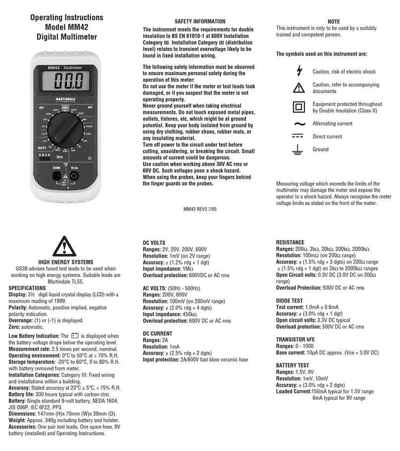
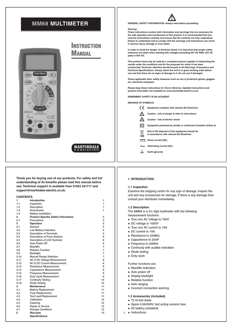
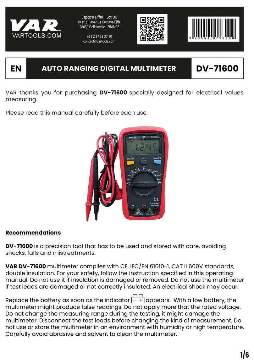
MARTINDALE MM37 User manual

Martindale Electric will carry out routine calibration (on a chargeable basis)
if the instrument is returned, carriage paid, to the address on the final page
of this document. Alternatively, a chargeable collection and return service is
available.
4.5 Repair & Service
There are no user serviceable parts in this unit. Return to Martindale
Electric Company Ltd if faulty, unless fuse replacement only is necessary.
Our service department will promptly quote to repair any faults that occur
outside the warranty period.
4.6 Storage Conditions
The MM37 should be kept in warm, dry conditions away from direct
sources of heat or sunlight, with the battery removed and in such a manner
as to preserve the working life of the multimeter. It is strongly advised that
the unit is not kept in a tool box where other tools may damage it.
4.7 Warranty
Faults in manufacture and materials are fully guaranteed for 2 years from
date of invoice and will be rectified by us free of charge, provided the unit
has not been tampered with and is returned to us with its housing
unopened. Damage due to dropping, abuse or misuse is not covered by the
guarantee. Nothing in these instructions reduces your statutory rights.
Martindale Electric Company Limited
Metrohm House, Penfold Trading Estate, Watford, WD24 4YY, UK.
Tel: +44(0)1923 441717 Fax: +44 (0)1923 446900
E-mail: [email protected]
Website: www.martindale-electric.co.uk
© Martindale Electric Company Ltd.
Registered in England No. 3387451. Rev 1. July 2005
MM37 DIGITAL MULTIMETER
MARTINDALE
ELECTRIC
Trusted by professionals
INSTRUCTIONS

SAFETY INFORMATION: Always read before proceeding.
WARNING
These instructions contain information and warnings that are necessary for safe
operation and maintenance of the MM37. It is recommended that you read the
instructions carefully and ensure the contents are understood. Failure to
understand the instructions and comply with warnings and instructions herein
can result in serious injury, damage or even death.
In order to avoid the danger of electrical shock, it is important that proper safety
measures are taken when working with voltages exceeding 30V AC rms, 42V AC
peak or 60V DC. Never exceed the maximum allowable input level for each
function and range. Refer to the specifications for maximum inputs. Never
touch exposed wiring, connections or live circuits.
The MM37 must only be used in conditions and for the purpose which it has
been constructed. Attention should be paid to safety instructions, technical
specifications and use of the MM37 in dry surroundings.
Always inspect your meter, test leads and accessories for any sign of damage
before use. If any abnormal conditions exist (e.g: broken test leads, cracked
case, display not reading, etc.), do not attempt to use it. Do not expose it to
direct sunlight, excessive temperature or moisture.
Keep these instructions for future reference. Updated instructions and product
information are available at: www.martindale-electric.co.uk.
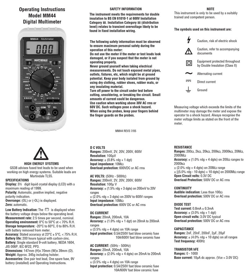
SYMBOLS: Equipment complies with relevant EU Directives
AC (Alternating Current)
Ground
Direct Current
Equipment protected by Double Insulation (Class II)
Caution - refer to accompanying documents
Caution - risk of electric shock
4. MAINTENANCE
4.1 Cleaning
Maintenance consists of periodic cleaning and battery replacement.
The exterior of the instrument can be cleaned with a dry clean cloth to
remove any oil, grease or grime. Never use liquid solvents or detergents.
Repairs or servicing not covered in this manual should only be performed
by qualified personnel.
4.2 Battery Replacement
WARNING - To avoid electrical shock, disconnect the test leads and
any input signals before replacing the battery. Replace only with the
same type of battery.
This meter is powered by NEDA type 1604 or equivalent 9V battery. When
the meter displays the “ ” symbol, the battery must be replaced to
maintain proper operation. To replace the battery, remove the three screws
from the back of the meter and open the bottom case, remove the battery
from battery compartment and replace it with a new one.
4.3 Fuse Replacement
If no current measurements are possible, check for a blown overload
protection fuse. There are two fuses: F1 for the µA/mA socket and F2 for
the 10A socket. For access to fuses, remove the three screws from the
back of the meter and open the bottom case. Replace F1 only with the
original type 0.5A/250V, fast acting fuse (part no: FUSE500250).
Replace F2 only with the original type 10A/600V, fast acting ceramic fuse
(part no: FUSE10600).
4.4 Calibration
The recommended calibration interval is 12 months.
211

CONTENTS
1 Introduction
1.1 Description
1.2 Unpacking And Inspection
1.3 Battery Installation
2 Technical Specification
3 Operation
3.1 Precautions
3.2 Range Selection
3.3 Hold Button
3.4 DC/AC Button
3.5 Audible Continuity/Diode Button
3.6 Continuity Test
3.7 Non-Contact Voltage Indicator
3.8 Maximum Reading Mode
3.9 Hold Button
4 Maintenance
4.1 Cleaning
4.2 Battery Replacement
4.3 Fuse Replacement
4.4 Calibration
4.5 Repair & Service
4.6 Storage Conditions
4.7 Warranty
3.7 Non-contact voltage indicator
1. Remove the test leads from the meter.
2. The rotary function / range switch may be set to any position.
3. Press and hold the “NC” button. The meter will produce a brief buzz and
the display will blank.
4. With the “NC” button continuously held, the sensor “S” on the top of the
meter should be directed towards the point where 50/60Hz AC voltage is
expected. Move the unit as near as is practical. The presence of a voltage
greater then 70V will produce an audible tone, with visible indication.
3.8 Maximum reading mode
A single press of the “MAX” button with a signal connected and AC/DC
voltage, AC/DC current or resistance selected, will enter this mode.
The “MAX” symbol appears in the top left of the display and the reading
updates to show each new higher value measured. A further press of the
“MAX” button exits the mode.
3.9 HOLD button
This button toggles in and out of the Data Hold mode, which maintains the
present reading on the display.
An “H” symbol is shown on the display until the Hold button is pressed
again, which exits the mode.
310

3.3 Current measurement
1. Select the correct current range, using the rotary switch.
2. For inputs less than 200mA, connect the red test lead to the uA/mA
socket, and the black lead to the COM socket.
3. For inputs greater than 200mA, connect the red lead to the 10A socket,
& the black lead to the COM socket.
4. Remove power from the circuit, open the circuit path for the
measurement and connect the meter in series with it.
5 Apply power and take the reading shown on the display.
3.4 Resistance measurement
1. Select the required resistance range.
2. Remove power from the circuit under test.
3. Connect the red test lead to the "VΩ" socket and black lead to "COM"
socket.
4. Connect the test leads to the measurement points and take a reading.
3.5 Diode test
1. Select the " " switch position.
2. Connect the red test lead to the "VΩ" socket and black lead to "COM"
socket.
3. Remove power from the circuit under test.
4. Touch the probes across the diode and take a reading, reverse the
probes and again take a reading. For a silicon diode, a value between 0.5
& 0.6 should be obtained in the forward direction, and "1." should be
displayed for the reverse direction. A value of "1." in both directions
indicates open circuit, a lower reading than 0.5 in either direction indicates
a shorted diode.
3.6 Continuity test
1. Select the " " rotary switch position.
2. Remove power from the circuit under test.
3. Connect the red test lead to the "VΩ" socket and black lead to "COM"
socket.
4. Connect the test leads to the measurement points. The buzzer sounds
for resistance values less than about 100Ω.
1. INTRODUCTION
1.1 Description
The MM37 is a full function multimeter having AC/DC voltage, AC/DC
current, resistance, diode & continuity tests.
A Max mode enables the meter to display only the maximum value of a
changing signal, which constantly updates.
Pressing Hold once freezes the reading and a second press restores
normal operation.
The meter has two separately fused, current input positions.
The non-contact voltage indicator operates from any position of the central
rotary switch and is activated by pressing the “NC” button.
1.2 Unpacking & Inspection
Before unpacking the MM37, examine the shipping carton for any sign of
damage. Unpack and inspect the MM37 for any sign of damage. If there is
any damage then consult the supplier immediately.
1.3 Battery Installation
Refer to section 4.2 for battery installation instructions.
4 9

2. TECHNICAL SPECIFICATION
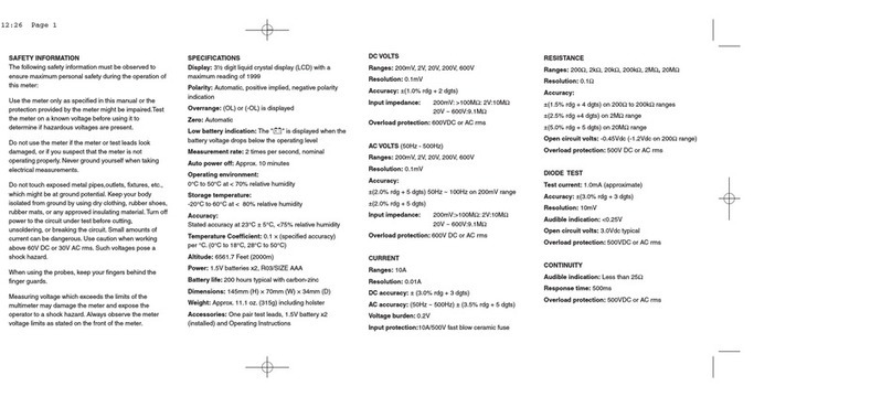
Display: 3.5 digit liquid crystal (LCD), maximum reading 3200 with floating
decimal point. Updates at 2.5 times per second.
Polarity: Automatic, implied for positive values, "-" to show negative
readings.
Overrange: OL or -OL is displayed.
Zero: Automatic.
Low battery indication: A " " symbol appears when the voltage drops
below that required for correct operation.
Auto Power Off: After approx. 10 minutes.
Operating: 0 to 50°C @ < 70% relative humidity (RH).
Storage: -20 to 60°C, 0 to 80% RH (battery must be removed).
Temperature coefficient: Add (0.1 x % accuracy) per °C from 0 to 18°C,
and from 28 to 50°C.
Maximum altitude: 2,000m.
Battery: 1 x 9 volt, type PP3, MN1604, NEDA1604, JIS006P, IEC 6F22.
Battery life: 200 hours, typical (Zinc - carbon).
Dimensions: 143 x 68 x 47mm (5.6 x 2.7 x 1.9 inches).
Weight: 206g (7.3oz) with battery fitted.
Included: Set of test leads, 9V battery (fitted) & user manual.
DC VOLTS
Ranges: 200mV, 2V, 20V, 600V.
Resolution: 100µV
Accuracy: ± 1.2% rdg + 1 digit
Input impedance: 10MΩ
Overload protection: 600V DC or AC rms
500V DC / 350V rms for 15 secs on 200mV range
AC VOLTS (50Hz to 500Hz)
Ranges: 200mV, 2V, 200V, 600V
Resolution: 100µV
Accuracy: ± (2% rdg + 4 digits)
Input impedance: 10MΩ
Overload protection: 600V DC or AC rms
500V DC / 350V rms for 15 secs on 200mV range
3. OPERATION
3.1. Precautions
Warning: Before using the instrument, read the Safety Information
Section, and examine it for damage or contamination (excessive dirt,
grease, etc.). Check the test leads for any evidence of cracked or
frayed insulation. If any abnormal conditions exist, do not use the
meter.
Warning: When using probes, keep your fingers behind the guards.
Warning: Measuring voltages which exceed the limits of the meter
may damage it and expose the operator to a shock hazard. Always
work within the meter voltage limits indicated on it's front panel.
Warning: Never ground yourself when taking electrical
measurements. Do not touch exposed metal pipes, outlets, fixtures
etc. which may be at ground potential. Keep your body insulated by
wearing dry clothing, rubber shoes or stand on a rubber mat, or other
suitable material.
3.2 Voltage measurement
1. Connect the red test lead to the "VΩ" socket, and the black lead to the
"COM" socket.
2. Select the correct function & range using the rotary switch, ensuring that
AC, or DC, ranges are chosen as appropriate. If the magnitude of the
signal is uncertain, then begin with the highest setting, and reduce it until a
satisfactory indication is obtained.
3. Connect the other end of both test leads to the unit under test.
4. In the DC function a "-" is displayed for negative values, positive
indication is implied.
58

DC CURRENT
Ranges: 200µA, 20mA, 200mA, 10A
Resolution: 0.1µV
Accuracy: ± (1.5% rdg + 1 digit) except 10A range
± (3% rdg + 3 digits) on 10A range
Input protection: 0.5A, 250V fast blow & 10A, 600V fast blow ceramic,
fuse.
AC CURRENT (50Hz to 500Hz)
Ranges: 200µA, 20mA, 200mA, 10A
Resolution: 0.1µA
Accuracy: ± (2% rdg + 4 digits) except 10A range
± (3.5% rdg + 4 digits) on 10A range
Input protection: 0.5A, 250V fast blow & 10A, 600V fast blow ceramic,
fuse.
RESISTANCE
Ranges: 200Ω, 20kΩ, 200kΩ, 20MΩ
Resolution: 100mΩ
Accuracy: ± (1.5% rdg + 4 digits) except on 20MΩrange
± (3% rdg + 4 digits) for 20MΩrange
Open circuit voltage: 0.3V DC typical (3V DC for 200Ωrange)
CONTINUITY
Audible tone: <100Ω
Response time: 500mS
Overload protection: 500V DC or AC rms.
DIODE TEST
Test current: Approximately 1mA
Accuracy: ± (2% rdg + 1 digit)
Open circuit voltage: 3V DC typical
Non-contact Voltage Indicator: Operates for voltages from 70V to 480V
AC, 50-60Hz.
NOTE:
This instrument complies with class ll, overvoltage CAT lll, 600V of the
IEC1010-1 (EN61010-1) standard and pollution degree 2 in accordance
with IEC-664 indoor use.
This instrument also complies with the requirements of the following
European Community Directives: 89/336/EEC (Electromagnetic
Compatibility) and 73/23/EEC (Low Voltage) as amended by 93/68/EEC
(CE Marking).
However, electrical noise or intense electromagnetic fields in the vicinity of
the equipment may disturb the measurement circuit. Measurement
instruments will also respond to unwanted signals that may be present.
Users should exercise care and take appropriate precautions to avoid
misleading results in the presence of electromagnetic interference.
6 7
Table of contents
Other MARTINDALE Multimeter manuals

MARTINDALE
MARTINDALE AM5 User manual

MARTINDALE
MARTINDALE MM42 User manual

MARTINDALE
MARTINDALE MM35 User manual

MARTINDALE
MARTINDALE MM47 User manual

MARTINDALE
MARTINDALE MM84 User manual

MARTINDALE
MARTINDALE MM34 User manual

MARTINDALE
MARTINDALE VERITEST 2240 User manual

MARTINDALE
MARTINDALE MM44 User manual

MARTINDALE
MARTINDALE MM94 User manual

MARTINDALE
MARTINDALE MM68 User manual