MARTINDALE VERITEST 2240 User manual

VERITEST 2240 ALL-IN-ONE
MARTINDALE
ELECTRIC
Trusted by professionals
QUICK START
Other products from Martindale:
G16th Edition Testers
GAll-in-one’s
GCalibration Equipment
GContinuity Testers
GElectrician’s kits
GFull Calibration & Repair Service
GFuse Finders
GDigital Clamp Meters
GDigital Multimeters
GMicrowave Leakage Detectors
GMotor Maintenance Equipment
GNon-trip loop testers
GPat testers & Accessories
GPhase rotation
GProving units
GSocket Testers
GThermometers & Probes
GTest Leads
GVoltage Indicators
GSpecialist Metrohm testers (4 & 5kV)
GSpecialist Drummond testers
Martindale Electric Company Limited
Metrohm House, Penfold Trading Estate, Watford, WD24 4YY, UK.
Tel: +44(0)1923 441717 Fax: +44 (0)1923 446900
E-mail: [email protected]
Website: www.martindale-electric.co.uk
© Martindale Electric Company Ltd. 2005
Registered in England No. 3387451. Rev 8


CONTENTS
THIS IS DESIGNED TO BE USED AS A QUICKSTART GUIDE ONLY.
COMPREHENSIVE INSTRUCTIONS ARE AVAILABLE FOR DOWNLOAD AT
www.martindale-electric.co.uk/instruct.htm
1 Calibration of test leads 3
2 LOW Ω continuity test 4
3MΩ insulation test 5
4 RCD test 6
5 Loop - Zs / IK 9
6 Non Trip Earth Loop Impedance Test (Ra15mA) 10
@1Ω resolution with PFC calculation
7 Phase Rotation/Sequence 11
8 Instrument Connection to a PC 14
9 Specification 15
10 Accessories 19
11 Maintenance 19
ALL TESTING TO BE CARRIED OUT IN ACCORDANCE WITH
WIRING REGULATIONS IEE 16TH EDITION, BS 7671-2001
USER NOTES

2
SAFETY INFORMATION: Always read before proceeding.
WARNING
These instructions contain information and warnings that are necessary for
safe operation and maintenance of the Veritest. It is recommended that you
read the instructions carefully and ensure the contents are understood.
Failure to understand the instructions and comply with warnings and
instructions herein can result in serious injury, damage or even death.
In order to avoid the danger of electrical shock, it is important that proper
safety measures are taken when working with voltages exceeding 30V AC
rms, 42V AC peak or 60V DC. Never exceed the maximum allowable input
level for each function and range. Refer to the specifications for maximum
inputs. Never touch exposed wiring, connections or live circuits.
The Veritest must only be used in conditions and for the purpose which it
has been constructed. Attention should be paid to safety instructions,
technical specifications and use of the Veritest in dry surroundings.
Always inspect your meter, test leads and accessories for any sign of
damage before use. If any abnormal conditions exist (e.g: broken test leads,
cracked case, display not reading, etc.), do not attempt to use it. Do not
expose it to direct sunlight, excessive temperature or moisture.
Keep these instructions for future reference. Updated instructions and
product information are available at: www.martindale-electric.co.uk
SYMBOLS:
Equipment complies with relevant EU Directives
AC (Alternating Current)
Ground
Direct Current
Equipment protected by Double Insulation (Class II)
Caution - refer to accompanying documents
Caution - risk of electric shock
10. OPTIONAL ACCESSORIES
Infra red data lead
VRTL1
Download software
VRSOFT1
Mini printer
VRPRINT1
Data Lead VRPRINT1 to VR2240
TL130
Test lead (GB 13A plug)
TL206
Fused test lead set
TL54
11. MAINTENANCE
Cleaning
Maintenance consists of periodic cleaning.
The exterior of the instrument can be cleaned with a dry clean cloth to
remove any oil, grease or grime. Never use liquid solvents or detergents.
Repairs or servicing not covered in this manual should only be performed by
qualified personnel.
Calibration
The recommended calibration interval is 12 months.
Martindale Electric will carry out routine calibration (on a chargeable basis) if
the instrument is returned, carriage paid, to the address on the final page of
this document. Alternatively, a chargeable collection and return service is
available.
Repair & Service
There are no user serviceable parts in this unit. Return to Martindale Electric
if faulty. Our service department will promptly quote to repair any faults that
occur outside the warranty period.
Storage Conditions
The Veritest should be kept in warm, dry conditions away from direct sources
of heat or sunlight and in such a manner as to preserve the working life of the
instrument.
Warranty
Faults in manufacture and materials are fully guaranteed for 24 months from
date of invoice and will be rectified by us free of charge, provided the unit has
not been tampered with and is returned to us with its housing unopened.
Damage due to dropping, abuse or misuse is not covered by the guarantee.
Nothing in these instructions reduces your statutory rights. 19

3
1. CALIBRATION OF TEST LEADS
1) Connect red & black test leads to P + N terminals respectively.
2) Turn dial to low Ω (continuity setting). Display shows 'LOW Ω' at top left.
3) Press key repeatedly until 'CAL' is shown on display.
4) Connect/Short circuit test leads together so good contact is made.
5) Press yellow key. 'MEASURING' briefly appears on the display -
Calibration is being carried out. The test lead resistance is shown briefly,
before the screen zeros.
6) When calibration is complete, 2 beeps are heard and 'MEASURING' is
not displayed.
NB: To remove test lead compensation, repeat procedure above, but with test
leads open circuit.
This function enables the instrument to measure the resistance of the test leads
and commits the measurement to memory. Once this has been carried out, the
test lead resistance is automatically subtracted from any continuity measurement,
thus giving more accurate results.
This compensation value is retained when the instrument is powered down and
when batteries are removed for replacement.
CAL LOWΩ
0.00Ω
219mA
the instrument has
a stored value for
the resistance of
the test leads
current supplied by
instrument during
calibration
procedure
function selected
FUNC
GO
NON TRIP EARTH LOOP TEST: (RA15MA )
Measuring Resolution Accuracy
1-1999Ω1ΩRes ±(5%rdg+2dgt)
PFC 1-999 Amps, 1.0-20.0KA
Test current 15mA
Battery type: 6x1.5V LR6-AA-AM3-MN1500
Low battery indication: Yes
Battery life: About 40 hrs in stand-by or 500 Continuity tests or
250 Insulation tests 500V/500k or
1000 LOOP/RCD/PHASE SEQUENCE TESTS
Weight: (batteries included) 1000gm
Dimensions: 222mm(L) x 162mm(W) x 57mm(D)
Phase Rotation Test: graphic display of phase sequence
Memory Slots For Saved Tests: 350
Display Features: LCD custom
Interface optical: RS232 to print or to download the tests
Please refer to the accessories section for test leads.
SAFETY STANDARDS
The instrument complies with: EN 61010-1 + A2 (1997), EN61557, EN61326-1
(1997) + A1 (1998).
Insulation: Class 2, double insulation
Pollution degree: 2
Inside use: max altitude - 2000m
Overvoltage category: CAT III 460V~P-N-E / 265V~ to earth
ENVIRONMENT
Environmental working conditions
Reference temperature: 23° ± 5°C
Working temperature: -10°C – 50 °C
Relative humidity allowed: <80%
Storage temperature: -20 – 60 °C
Storage humidity: <80%
18

4
2. LOW ΩCONTINUITY TEST
1) Connect red & black test leads to P + N terminals respectively.
2) Turn dial to low Ω(continuity setting). Display shows 'LOW Ω' at top left.
3) Select: 'Auto', 'R+', 'R-', 'R+TIMER', 'R-TIMER'. By repeated pressing of
the key. See below for details of individual tests.
If using the timer function, set time using + keys
4) Connect the test leads to the conductors on which the continuity test is to
be carried out.
5) Press yellow key – The instrument performs the test
Auto: The instrument carries out 2 measurements. 1x positive polarity and
1 x negative polarity. The instrument displays an average reading of
the two measurements performed.
R+: The instrument carries out 1 measurement with a positive polarity. I.E.
Red test lead positive.
R-: The instrument carries out 1 measurement with a negative polarity.
I.E. Black test lead positive
R+TIMER: The instrument carries out 1 measurement with a positive polarity and
an adjustable duration of test. Min 3 seconds, Max 15 seconds. Use
+ to set test duration.
R-TIMER: The instrument carries out 1 measurement with a negative polarity and
an adjustable duration of test. Minimum of 3 seconds, Maximum of
15 seconds.
Use + to adjust time up and down respectively.
At the end of the test, if the resistance value is lower than 5Ω, the instrument
beeps twice, indicating low resistance. The resistance value is displayed on the
screen.
NB Cal & Low Ωis displayed in the top left of the screen if a lead compensation
value is stored; this value will be applied to any measurement made.
L
SULM
L
SULM
L
SULM
FUNC
GO
AC VOLTAGE:
Electrical Syst Range(V) Resolution(V) Accuracy
Single-phase 0 - 265 1 ±(2% rdg + 2 dgt)
2 or 3 - phase 0 - 460 1 ±(5% rdg + 2 dgt)
FREQUENCY:
Range(V) Resolution HZ Accuracy
15.3 - 99.9 Hz 0.1 HZ ±(0.1% rdg + 1 dgt)
LINE IMPEDANCE
(LOOP ZS/IK PHASE TO PHASE OR PHASE TO NEUTRAL)
Test mode Range Resolution Accuracy
(P-P & P-N) 0.03-19.99Ω(0.01ΩRes) ±(5% rdg + 2 dgt)
20.0-199.9Ω(0.1ΩRes) ±(5% rdg + 2 dgt)
PSC 1-999A
1.0-20.0KA
Test voltage: VPN 100V - 265V 50Hz + 0.5 Hz
VPP 100V - 460V 50Hz + 0.5 Hz
Max peak test current: 100V 3.17A test duration: 80ms
230V 6.64A test duration: 40ms
400V 11.5A test duration: 40ms
Accuracy current measurement: ±10% Imax Pk
PHASE EARTH IMPEDANCE (LOOP ZS/IK)
Range Resolution Accuracy
0.03-19.99Ω(0.01ΩRes) ±(5%rdg+2dgt)
20.0-199.9Ω(0.1ΩRes) ±(5%rdg+2dgt)
200-1999Ω(1ΩRes) ±(5%rdg+2dgt)
PFC 1-999A, 1.0-20.0KA
Max peak test current: 100V 3.17A test duration: 80ms
230V 6.64A test duration: 40ms
Accuracy current measurement: ±10% Imax Pk
Test frequency: VPE 100V - 265V 50Hz +0.5 Hz
17

5
3. M ΩINSULATION TEST
1) Connect the red and black test leads to P + N terminals respectively
2) Turn dial to M Ω(insulation resistance). Display shows 'Riso' at top left.
3) Select 'MAN', 'AUTO' or 'TIMER' mode by repeatedly pressing the
key. See below for details of individual tests.
4) Press repeatedly to select the voltage suitable for the test being
carried out. 50V, 100V, 250V, 500V, 1000V.
5) Connect the test leads to the conductor on which the insulation test is to
be carried out.
6) Press yellow key. The instrument performs the test as stated below.
At the end of the test, the instrument beeps twice indicating a successful
measurement. The resistance is displayed on the screen.
If the insulation is very low value the tester emits a long single beep to indicate
that the test voltage fell below the set rated voltage and the measurement was
unsuccessful.
See technical specification.
MAN: Minimum test time of 5 or 10 seconds depending on test voltage and
insulation resistance. See table below. If “Go” is pressed and held for
longer than 10 seconds, the instrument continues to measure until the
“Go” key is released.
AUTO: The test ends when the measured value becomes stable.
TIMER: Test duration can be adjusted from 10-999 seconds. Adjust values
using or This test can be used if a minimum
measuring time is required.
UN/IΔn
FUNC
L
SULM
GO
100V 250V 500V 1000V
Low resistance 5 seconds 10 seconds 10 seconds 10 seconds
High resistance 5 seconds 5 seconds 5 seconds 5 seconds
Open circuit voltage: Rated voltage test -0% +10%
Short circuit current: <3,0mA @ 500V
<2,0mA @ 50V, 100V, 250V, 1000V
Test current on load: >1mA @ VTest across R load =(1000 x VTest)Ω
If the instrument measures a voltage higher than 30V, the instrument does not
perform the test
RCD
Type of RCD: AC, A
Range of phase to earth voltage: (100 - 265) V
Rated Tripping Current (IΔΔN): 10mA, 30mA, 100mA, 300mA, 500mA
Test frequency: 50Hz ± 0.5 Hz
TRIPPING TIMES
Test Range Resolution Accuracy
½ IΔN, IΔN0-999ms 1ms ±(2%rdg+2dgt)
2 IΔN0-200ms general 1ms ±(2%rdg+2dgt)
0-250ms selective 1ms ±(2%rdg+2dgt)
5 IΔNRCD(*) 0-50ms general 1ms ±(2%rdg+2dgt)
0-160ms selective 1ms ±(2%rdg+2dgt)
(*) For RCD type A 500mA, the MAN x5 and AUTO tests are not available.
The Ramp test measures tripping current
CONTACT VOLTAGE
Measuring range(V) Resolution(V) Accuracy
0 - 2Ut Lim 0.1 -0%,+(10%rdg+2dgt)
Ut Lim (UL): 25V or 50V
TRIPPING CURRENT FOR RCD TYPE A AND AC
RCD with IΔN≤10mA
Type RCD Range IΔN(mA) Resolution(mA) Accuracy IΔN
AC (0.5 - 1.4) IΔN0.1 IΔN-0%, +10% IΔN
A (0.5 - 2.4) IΔN
RCD with IΔN≥10mA
Type RCD Range IΔN(mA) Resolution(mA) Accuracy IΔN
AC (0.5 - 1.4) IΔN0.1 IΔN-0%, +10% IΔN
A (0.5 - 2) IΔN
16

6
4. RCD TEST
1) Connect the red, black and green test leads, or the plug top lead to P,N +E
terminals respectively.
2) Turn the dial to RCD for RCD type A.C. sensitive to sine
leakage current, (general) or RCD for RCD'S type A sensitive to
pulsating leakage current (DC sensitive). Display shows RCD or
RCD at top centre.
3) Select: MAN x ½, MAN x1, MAN x 2, MAN x 5, AUTO, RAMP, Ut
by repeatedly pressing the function key See further
description on next page.
4) Select the rated tripping current of the RCD by repeatedly pressing the
key. (10mA, 30mA, 100mA, 300mA, 500mA) until the desired level is
reached.
5) If the test is to be carried out on a 'selective' time delayed RCD, the symbol
must be displayed. This function is controlled via the key and
is not available in ramp or Ut mode.
6) Select the limit for contact voltage (50V by default) by pressing
button.
(This cycles between 50V & 25V).
7) Connect either the mains plug to a 230V 50HZ socket outlet, or the croc
clips to the appropriate conductors on which the test is to be carried out.
8) A. Press the yellow key once. The instrument injects a current in
phase with positive half wave of the voltage. (indicated on display by O°).
B. Press the yellow key twice. The instrument injects a current in
phase with negative half wave of the voltage (indicated on display by
180°).
FUNC
UN/IΔn
L
S
S
UL M
GO
GO
9. SPECIFICATION
Accuracy is indicated as [% of reading + number of digits]. It refers to the
atmospheric conditions listed previously.
CONTINUITY:
Test mode Range Resolution Accuracy
AUTO, R+, R- 0.01-19.99Ω0.01Ω±(2%rdg+2dgt)
20.0-99.9Ω0.1Ω±(2%rdg+2dgt)
Timer Mode 0.01-9.99Ω0.01Ω±(2%rdg+2dgt)
Test current: >200mA DC up to 16Ω(include the resistance of the calibration)
40mA DC from 16Ωto 99.9Ω
Resolution: 1mA
Open circuit Test Voltage: 9V
Live Circuit Warning: Yes
Timer: test duration 10-999 seconds
INSULATION TESTS
Rated Test Measurable Range MΩ
Voltage at Rated Test Voltage Resolution Accuracy
50V 0.05-19.99 MΩ0.01MΩ±(2%rdg+2dgt)
20.0-49.9 MΩ0.1MΩ±(2%rdg+2dgt)
50.0-99.9 MΩ0.1MΩ±(5%rdg+2dgt)
100V 0.10-19.99 MΩ0.01MΩ±(2%rdg+2dgt)
20.0-99.9 MΩ0.1MΩ±(2%rdg+2dgt)
100.0-199.9 MΩ0.1MΩ±(5%rdg+2dgt)
250V 0.23-19.99 MΩ0.01MΩ±(2%rdg+2dgt)
20.0-199.9 MΩ0.1MΩ±(2%rdg+2dgt)
200-249 MΩ1MΩ±(2%rdg+2dgt)
250-499 MΩ1MΩ±(5%rdg+2dgt)
500V 0.25-19.99 MΩ0.01MΩ±(2%rdg+2dgt)
20.0-199.9 MΩ0.1MΩ±(2%rdg+2dgt)
200-499 MΩ1MΩ±(2%rdg+2dgt)
500-999 MΩ1MΩ±(5%rdg+2dgt)
1000V 0.90-19.99 MΩ0.01MΩ±(2%rdg+2dgt)
20.0-199.9 MΩ0.1MΩ±(2%rdg+2dgt)
200-999 MΩ1MΩ±(2%rdg+2dgt)
1000-1999 MΩ1MΩ±(5%rdg+2dgt)
Automatic selection of the measuring range
15

7
MAN x ½ the instrument performs the test with a leakage current at ½x
the value of the rated current indicated, with the leakage current
in phase with the voltage or phase shifted by 180° with respect
to the voltage.
MAN x 1 the instrument performs the test with a leakage current at 1x the
value of the rated current indicated, with the leakage current in
phase with the voltage or phase shifted by 180° with respect to
the voltage.
MAN x 2 the instrument performs the test with a leakage current at 2x the
value of the rated current indicated, with the leakage current in
phase with the voltage or phase shifted by 180° with respect to
the voltage.
MAN x 5 the instrument performs the test with a leakage current at 5x the
value of the rated current indicated, with the leakage current in
phase with the voltage or phase shifted by 180° with respect to
the voltage
AUTO the instrument performs the test automatically with a leakage
current at ½x, 1x, 5x the value of the rated current indicated with
the leakage current in phase with the voltage and then phase
shifted by 180° with respect to the voltage. Recommended test.
.
RAMP Mode the instrument performs the test with a steadily increasing
leakage current, with the leakage current in phase with the
voltage or phase shifted by 180° with respect to the voltage.
Use this test to measure the tripping current.
UtMode the instrument performs the test with a leakage current equal to
½ the value of the rated current indicated and calculates the
contact voltage as well as the Ra earth resistance with the
leakage current in phase with the voltage or phase shifted by
180° with respect to the voltage.
Readings below 1Ω are displayed as 1Ω.
PLEASE NOTE:
MAN x5 and auto test modes are not available for RCD type A, 500mA
8. INSTRUMENT CONNECTION TO PC OR A PRINTER
The connection from the VR2240 to a PC is made using the optional infra red
data lead VRTL1 connected to the PC serial port. The optional software package
VRSOFT1 provides the facility to download and print results onto a form (All
items sold separately).
Before connecting the VR2240 to a PC, it is necessary to select and configure
the COM port on the PC used for data transfer. To set this, start the software and
refer to the help provided with the VRSOFT1 download application.
The selected port should NOT be shared by other devices or applications (eg.
mouse, modem, etc.).
The connection from the VR2240 to the printer VRPRINT1 is made using the infra
red data lead VRTL1, in conjunction with printer adaptor cable TL130 (all items
sold separately).
To transfer the stored data from the instrument to the PC or printer, follow the
directions below.
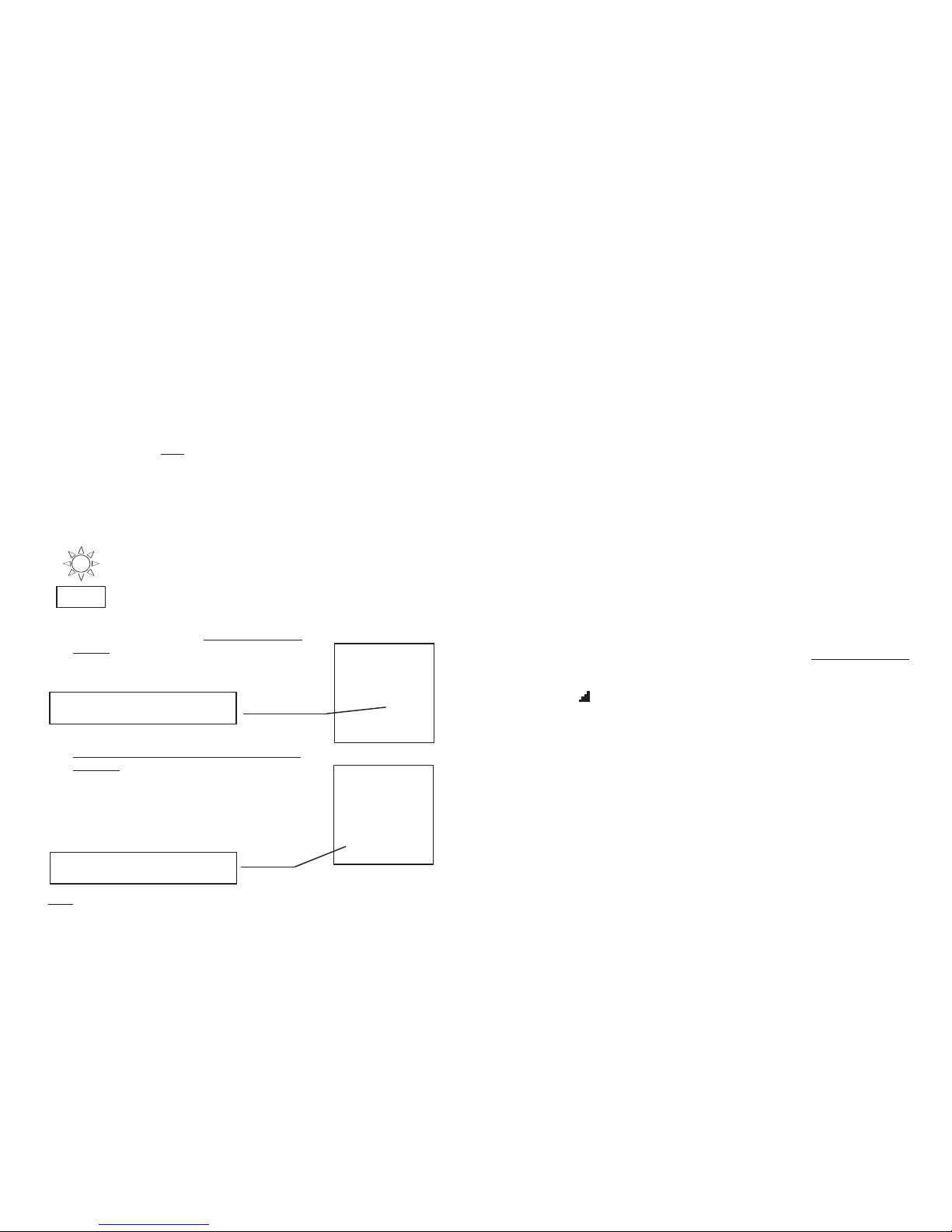
1. Turn the rotary switch to the RS232 position.
2. Using the FUNC key, select the modes "Prn ALL" or "Prn
n1 n2", to display the following screens respectively:
14
FUNC
Press GO to start printing all of the stored test
results.
Press ESC to stop printing immmediately.
indicates the total number of results
stored in memory.
Press GO to start printing the test results from
memory locations n1 to memory locations n2
inclusive. Note that the printing order is that of
the increasing value of the parameter P, NOT
memory location order. Ensure the range n1
to n2 covers all the results you need.
Press ESC to stop printing immediately.
indicates the memory cell which will
be printed as the last one.
Prn
All 125
Prn
13
25
Note Transmission speed on the PC or printer is set to 4800 baud to match
the output from VR2240.

8
Test results:
MAN x ½: If the RCD does not trip, the instrument beeps twice
indicating a successful outcome. (see screen on unit)
MAN x1, x2, x5: If the RCD trips within limits, the instrument beeps twice
suggesting a successful outcome. (see screen on unit).
Please note that the internal values apply for RCDs
manufactured to comply with BSEN61008. RCDs which are
manufactured to comply with BS4293 are required to operate in
0.2s at 1X IΔN. It is important that the user of this instrument is
aware of the applicable tripping time(s) for the RCD being
tested.
Please refer to the full user manual for tripping times.
AUTO: The instrument carries out the following 6 tests with different
values of rated current.
½ x IΔn @ 0° - The RCD should not trip
½ x IΔn @ 180° - The RCD should not trip
1 x IΔn @ 0° - The RCD trips (blinking RCD) - Switch RCD on again
1 x IΔn @ 180° - The RCD trips (blinking RCD) - Switch RCD on again
5 x IΔn @ 0° - The RCD trips (blinking RCD) - Switch RCD on again
5 x IΔn @ 180° - The RCD trips (blinking RCD) - Switch RCD on again
'OK' displayed - test passed.
Please refer to the full user manual for tripping times.
Press to scroll through the test results
RAMP: The instrument generates a leakage current growing step by
step in a given time interval. At the end of the test, if the RCD
tripping current is < IΔn (type AC) or 1.4xIΔn ( type A with
IΔn>10mA ) the instrument beeps twice indicating a positive
outcome of the test.
If the parameters set on the instrument are consistent with the
RCD under test, the ramp test will cause RCD tripping with a
current lower than or equal to the selected rated differential
current.
Ut: Press yellow key once. The instrument carries out the
test. If the RCD does not trip, the instrument beeps twice
indicating a successful outcome of the test.
GO
DISP
13
CLEARING TEST RESULTS
To clear results, proceed as follows:
1) Press the key
2) Navigate to the desired test using and keys.
3) Press the key to display the selected test result.
4) Press once. flashes in the display.
To cancel deletion press
5) Press again to permanently delete the test result, from the one
selected to the last one saved
WARNING The instrument will delete the all results stored from the memory
location selected to the last full one.
CLR
L
SUL M
DISP
CLR
RCL
CLR
ESC

9
5. LOOP - ZS / IK
PHASE TO NEUTRAL TESTING (PN)
1) Connect the red, black and green leads, or plug top lead, to P,N + E
terminals respectively.
2) Turn the dial to loop Zs/Ik. Display shows 'LOOP' at the top centre.
3) Press key repeatedly to select P-N. 'P-N' is shown.
4) Connect the mains plug to a 230V 50Hz socket outlet, or the croc clips to
appropriate conductors on which the test is to be carried out.
5) Press the yellow key to start the test.
6) At the end of the test, the instrument beeps twice indicating a positive
outcome of the test with the relevant results displayed.
PHASE TO PHASE TESTING (P.P.)
1) Connect the red, black and green leads to P,N + E terminals respectively.
2) Turn the dial to loop Zs/Ik. Display shows 'LOOP' at the top centre.
3) Press key repeatedly to select P-P. 'P-P' is shown.
4) Connect green test lead to the earth (PLE) conductor. Connect the red and
black test leads to each pair of phase conductors in turn, P1 & P2, P2 &P3,
P3 & P1, and press the key for each pair.
6) At the end of the test, the instrument beeps twice indicating a successful
outcome of the test with the relevant results displayed.
PHASE TO PROTECTIVE EARTH (P-PE)
1) Connect the red, black and green cables to P,N + E terminals respectively.
2) Turn the dial to loop Zs/Ik. Display shows 'LOOP' at the top centre.
3) Connect the mains plug to a 230V 50HZ socket outlet or to the
appropriate conductor by means of the croc clips
4) Press key repeatedly to select P-PE. 'P-PE' is shown.
5) Press the yellow key once. The instrument carries out the
test injecting a current in phase with positive half wave of the voltage
indicated on display by 0°
OR
Press the yellow key twice. The instrument carries out the test
injecting a current in phase with negative half wave of the voltage
indicated on display by 180°.
At the end of the test, the instrument beeps twice, indicating a positive outcome of
the test. The relevant results are displayed.
FUNC
FUNC
FUNC
GO
GO
GO
GO
12
SAVING TEST RESULTS
If test results are to be stored, proceed as follows:
a. After carrying out any successful test, press the key once.
b. Press either or to adjust the 'P' number up or
down. This is used to identify the test within a number of tests. When the
desired number is shown. Press save again to commit the test to memory.
The instrument beeps twice confirming that the test results have been stored.
c. Press to return to test mode.
RECALLING TEST RESULTS
If the test results are to be recalled, proceed as follows.
1) Press the key
2) Navigate to the desired test number using the and keys.
3) Press the button to display test result.
4) You can navigate to other test results by pressing and again.
5) Press to return to test mode.
MEM
SAVE
L
SUL M
2
P03
L
SUL M
L
SUL M
memory location
saved results
identify
RCL
DISP
ESC
ESC

6. Non Trip Earth Loop Impedance Test (Ra15mA) @1Ω resolution with PFC
calculation
1) Connect the red, black and green test leads to P, N+E terminals
respectively.
2) Turn the dial to the Ra 15 mA position. Display shows 'RCD' at the top
centre.
3) Connect the mains plug to a 230V 50HZ socket outlet, or to the appropriate
conductors on which the test is to be carried out using the croc clips.
4) Press the key to select the limit values for contact voltage 50V
(default) or 25V.
5) Press the yellow key to start the test.
6 At the end of the test, the instrument beeps twice indicating a positive out
come of the test. The relevant results are displayed.
PFC is displayed on lower RHS of Display in Amps
Readings below 1Ω are displayed as 1Ω
Formula for the prospective short circuit current:
Icc = UN
Ra
When UN = phase to earth voltage 127V if 100V < Vmeas ≤150V
230V if 150V < Vmeas ≤265V
This test is carried out at 15mA
10
UL M
GO
7. PHASE ROTATION/ SEQUENCE
1) Connect red, black and green test leads to P, N and E (L1, L2, and L3)
terminals respectively.
2) Turn dial to position.
3) Connect the test leads to the conductors on which the test is to be carried
out by using the croc clips.
4) The following screen is displayed:
5) Press the 'FUNC' key repeatedly to display the three differential voltages,
L1-2, L2-3, and L3-1 individually.
6) Press the yellow key to start the measurement of phase sequence.
The display must read '123' for correct phase sequence. This means that
the red test lead (connected to L1 ) is phase no 1. The black
test lead (connected to L2 ) is phase no 2, and the green test
lead (connected to L3 ) is phase no 3.
If '213' or '132' are displayed, then the phase sequence is incorrect.
11
386V
386V
386V voltage between
P2+ P3
voltage between
P1+ P2
voltage between
P3+ P1
GO
Table of contents
Other MARTINDALE Multimeter manuals

MARTINDALE
MARTINDALE CM54 User manual

MARTINDALE
MARTINDALE MM68 User manual

MARTINDALE
MARTINDALE MM39 User manual

MARTINDALE
MARTINDALE CM57 User manual

MARTINDALE
MARTINDALE MM37 User manual

MARTINDALE
MARTINDALE MM47 User manual

MARTINDALE
MARTINDALE MM42 User manual

MARTINDALE
MARTINDALE MM44 User manual

MARTINDALE
MARTINDALE MM64 User manual

MARTINDALE
MARTINDALE MM65 User manual