MASCOT UF-18C User manual

USER S MANUAL
BAND
DIVERSITY
WIRELESS
MICROPHONE
SYSTEM

WIRELESS MICROPHONE SYSTEM
1. Introduction
...
1
2. Safety
1
3. Environment
...
1
4. Wireless Note .... 1
5. Product Description .. ...
5.1 Receivers
5.2 Handheld Microphone
5.3 Bodypack Transmitter
2
6. Basic Connections ... ... ..
5
7. Setting Up ....
7.1 Connecting the receiver to power.
7.2 Connecting the receiver to an audio mixer or an amplifier.
7.3 Insertingbatteries into the handheld / bodypack transmitter
7.4 Settingup the handheld transmitter
7.5 Settingup the bodypack transmitter
7
8. Trouble-shooting .. ...
8
9. System Feature ....
9
10. System Specification .. .
9
Table of Contents

WIRELESS WIRELESS NOTE
1
FCC Statement
This device complies with part 15of theFCC rules. Operation is subject tothe following two
conditions: (1)This devicemay not cause harmful interferenceand (2) This devicemust accept
any interference received, including interferencethat maycause undesired operation
Notice: The changes ormodifications not expressly approved by theparty responsible for
compliance could voidthe user’s authority tooperate the equipment.
IMPORTANTNOTE: Tocomply with the FCC RF exposure compliance requirements, no
change totheantennaor thedevice ispermitted. Anychange tothe antennaor thedevice
could resultin the device exceeding the RF exposure requirements and void user’sauthority
to operate the device.
1. Introduction
Thank you for purchasing our product. This wireless microphone system operates in UHF
band frequency with synthesizer controlled. Thesystem with 16 or 64 selectablefrequencies
via PhaseLocked Loop (PLL) circuitry makes it easy to choosenon-interfered channels.
Pleaseread this instruction manual carefully before operating thesystem.This manual
covers the function and operationof thewireless microphone system.
2. Safety
ØDo not spillliquidon theapplianceand do not drop it on ahard concrete floor.
ØDo not place the appliance near heat sources such as radiators, amplifier, oretc. Donot
expose it todirect sunlight, extremely dust, excessive moisture, or vibration.
ØTakeout the battery from transmitter, if the appliance has beennot used fora longer
period. This will avoid the damage resulting from a defective leaking battery
3. Environment
ØDo not throwused batteries into afire or garbage bin with domestic rubbish. Be sure to
disposeof usedbatteries inaccordance with local waste disposal rules.
ØWhen disposing the equipment, remove the batteries, separatethe case, circuit boards,
and cables, and dispose of all components inaccordancewith local waste disposal rules.
4. Wireless Note
ØBefore setting up, make sure that the transmitter and receiver are tuned to the same
frequency.
ØDo not use two transmitters inthe same frequency.
ØUse good quality batteries toavoid the damage resulting fromadefective leakingbattery.
ØTurn thevolume controlon thereceiver to adjust receiver output level to match input level
requirements of amixer or amplifier. Pleasesee 7.2)
ØWhilechecking sound, move thetransmitter around the area where you use the systemto
look for dead spots. If you find any dead spot, change thereceiver position.If it does
not work, avoid suchplaces.
ØTo avoid interference, do not put the receiver toonear metal object and avoid obstructions
between transmitter and receiver.
ØAvoid theinterference fromTV, radio, otherwireless appliances and etc.
Wireless Microphone

¬
-
®
¯
°
±
²
³
´
11
15
13
14
2
5. Product Description
5.1 Receivers
This is a stationary diversity receiver for usewith our 16- or 64-channel selectable transmitters.
The receiver operates inUHF band frequency with PLL synthesized control. Powered by 12V DC.
1.
Power:
Pushes the receiver onand off.
2. Group LEDDisplay:Displays group number.
3. Channel LEDDisplay: Displays channel number.
´
µ
12
Wireless Microphone
WIRELESS PRODUCT DESCRIPTION

DC 12V
500mA
AUDIO OUTPUT
UNBALANCEDBALANCED SQUELCH
or
FOR
CHARGER
OPEN
WIRELESS PRODUCT DESCRIPTION
3
4.
Group Button:
Press this buttonto choosea displayed group number and the setting
group will be locked in5 seconds.
5. Channel Button: Press this button to choosea displayed channel number andthesetting
channel will be locked in5 seconds.
6. Set Button: Press this button tochoosea displayed group or channel number.
7. RF Level Indicators: Five LEDs per RF antenna channelglowto indicateRF signal
strength.Themore LEDs that glow, the stronger the received signal. If noneof these
LEDs glow, no signalis being received.
8. Level Control: This rotary control adjusts thereceiver output levelto match the input
sensitivityof anaudio mixer or amplifier
9. Antenna: Fixed-length UHF antenna permanently mounted on rear panel.
10. Balanced Output: 3-pin XLR connector provides balancedlow-impedance output
11. UnbalancedOutput: 6.3jphone jack provides unbalancedlow-impedance output
12. Squelch: The squelch adjusts the output level to suppress thenoise. Settingthe squelch
too high will reducethe usable range of the system. Set thesquelch to minimum before
turning the receiver on.
13. DC IN: Input connectorfor the supplied AC adapter.
14. Charger Input: Connect the supplied cableto the receiver and the microphone, and it
takes around 10 hours to rechargeand theLED of transmitter is flashing all the time.
15. Coil Strain: For the feeder cableof thesupplied ACadapter.
Wireless Microphone
ChargingConnectingDiagram
Connect the supplied DC1.5cableto the receiver and themicrophone, and it takes around
10 hours to recharge andthe LED of transmitter is flashing all the time.

CHANNEL
SELECTOR
1
1
54
2
3
6
CH.
8
7
54
2
3
GR.
6
8
7
¬
-
®
¯
°
±
²
³
WIRELESS PRODUCT DESCRIPTION
4
5.2 HandheldMicrophone
The handheld microphone operates inUHF band frequency with PLL synthesized control. UHF
16-or 64 preprogrammed selectable frequencies to avoid interference.Uni-directional dynamic
or uni-directional electret condenser capsules with different characters forvarious choices. Use
1.5V x2 AA size batteries for lowoperating cost.
1. Grille: Protects themicrophone capsule and helps reduce breathsounds and wind noise.
The grille for thevarious microphone capsules differ inappearance.
2. LowBatteryLED: LED indicates battery life status. Switching the power to "ON", theLED
flashing onceindicates that the transmitter has sufficient power. If the LED stayed on, it
indicates that the battery has insufficient power and shouldbe changed soon. If thestatus
LED fails to flash, the battery is either dead or not positioned correctly, and you shouldcorrect
the positioningor changethe battery.
3. On/off Switch: Turns transmitterpower on and off.
4. BatteryCompartment: Insert two AA dry or rechargeable batteries into the compartment
and makesurethat thepolarity of batteries is correct.
5. Group Selector: Changes transmitter Group setting.
6. Channel Selector: Changes transmitter Channelsetting.
7. BatteryCover: Unscrewto expose battery compartment and Group/Channel selector.
8. Color Clip: This color cliphelps to mark the same frequency of receiver and transmitter.
9. ChargingInput: Theinserted rechargeable batteries arecharged by using the supplied
DC-plug cable connection to DC out on the receiver.It takes up to 10 hours for charging.
Wireless Microphone
´

WIRELESS PRODUCT DESCRIPTION
5
5.3 Bodypack Transmitter
The bodypack transmitter operates inUHF band frequency with PLL synthesized control. UHF 16
or 64 preprogrammedselectable frequencies to avoidinterference. Uni-directional condenser
capsules with different characters for various choices. Use 1.5V x2 AA size dry or rechargeable
batteries for lowoperating cost.
1.
On/Off Switch:
Turns transmitter power on and off.
2. Mini XLR /3.5jconnector: Theincluded electret lapelmicrophone is inserted into the
connector on transmitter.
3. LowBatteryLED: LED indicates battery life status. Switching the power to "ON", the
LED flashing once indicates that the transmitter has sufficient power. If the LED stayed on,
it indicates that thebattery has insufficient power and should be changed soon. If thestatus
LED fails to flash, the battery is either dead or not positioned correctly, and you should
correct thepositioning or change the battery.
4. Mic/LineSelector (optional foruse with mini XLR connector) : The switchsets the
audio input either to microphone level or line level.
5. Antenna: Permanently connected, helical antenna.
6. Group Selector: Changes transmitter Group setting.
7. Channel Selector: Changes transmitter Channelsetting.
8. Gain.: The rotary control adjusts the sensitivity of the transmitter’s audio to the level of the
connected lapelmicrophone or instrument.
9. Mic Unit:The uni-directionalelectret condenser unit features the wide frequency response
for warm, richbass andclearsound.
10. Tie Clip:Toclip on the tie or lapel for free-movement.
11. Cable: Withmini XLR jack or 3.5jscrewtype plug cabletoconnect thetransmitter.
12. BatteryCompartment: Insert two AA dry or rechargeable batteries into the compartment
and makesurethat thepolarity of batteries is correct.
13. ChargingInput: for charging rechargeable batteries insidethebattery compartment using
the using a supplied cablewith 1.5jDC plugs. It needs up to 10hours forcharging.
Wireless Microphone
¬
-
®
¯
°
±
²
³
´
µ
12
13

AUDIO MIXER
AMPLIFIER
LOUDSPEAKER
LOUDSPEAKER
WIRELESS BASIC CONNECTIONS
6
6. Basic Connections
Connect the receiver output to the audio mixer or amplifierinput, using a standard audio cable
with 3-pin XLR connectors or6.3jphone plugs. Never use thebalanced and unbalanced
audio outputs at the same time!This may causesignalloss or increased noise.
Wireless Microphone

MAXMIN
VOLUME
VOLUME
MIN MAX
WIRELESS SETTING UP
7
7. Setting Up
NOTICE: Prior tosettingup, check that the transmitter andreceiver are tuned to thesame
frequency.Two or above transmitters operating in thesame frequency cannot be
used at thesame timeand area, so please select thedifferent frequencies which can
be used simultaneously at local area.
7.1 Connectingthe receiverto power
ØPlug the antennas into theTNC socket onthe receiver and point them upward.
ØCheck that thevoltage of thesupplied ACadapter conforms to the voltage available (AC110 or
220) in local area. Using the wrong AC adaptermay causeirreparable damage to theunit.
ØPlug the feeder cable of the supplied AC adapterintoDC INsocket on the receiver.Then
plug the AC adapter into apower outlet.
7.2 Connectingthe receiverto an audio mixer oran amplifier
In order tomake sure thesound quality and avoid distortion, pleaseadjust the volume level
according to following instructions.
7.3 Insertingbatteries intothe handheld/ bodypack transmitter
ØPushto openthe battery cover and insert batteries intothe battery compartment conforming to
the polarity (+)(-) marks. Thetransmitter can not work with incorrectly insertedbatteries.
ØWhen push the ON/OFFswitchto “ON”to switch the power on, the LED will flash momentarily.
If the battery has sufficient power, the LEDflashes once.If the LED stayed on, it indicates
that the battery has insufficient power and should be changed soon. If thestatus LED fails to
flash, the battery is eitherdead or not positioned correctly, andyou should correct the
positioningor change thebattery.
ØPushback the battery cover to click it shut.
7.4 Setting up thehandheldtransmitter
ØSwitch the receiver power on and check the frequency and volumelevel.
ØSwitch the transmitter andhi-fiappliance (amplifier, tape deck etc.) power on.
ØTest the microphone and adjust the levels onyour audio mixer or amplifier.
Wireless Microphone
ØWhen using astandard audio cable with 3-pin XLR connectors or 6.3
j
phone
plugs to plug into the MIC IN onthe audio mixer or on theamplifier, please turn
the VolumeLevel Controlon thereceiver to around 1o’clock position, the
output levelfor balanced and unbalanced output is about at 77mV.
ØWhen using astandard audio cable with 3-pin XLR connectors or 6.3jphone
plugs to plug into the LINE IN onthe audio mixer or on theamplifier, please
turn the VolumeLevel Control to around MAX. position on the receiver, the
output levelfor unbalanced and balanced output is about at 770mV.
Never use the balanced andunbalanced audio outputs at thesame time!This may cause
signal loss or increased noise.

WIRELESS TROUBLE SHOOTING
8
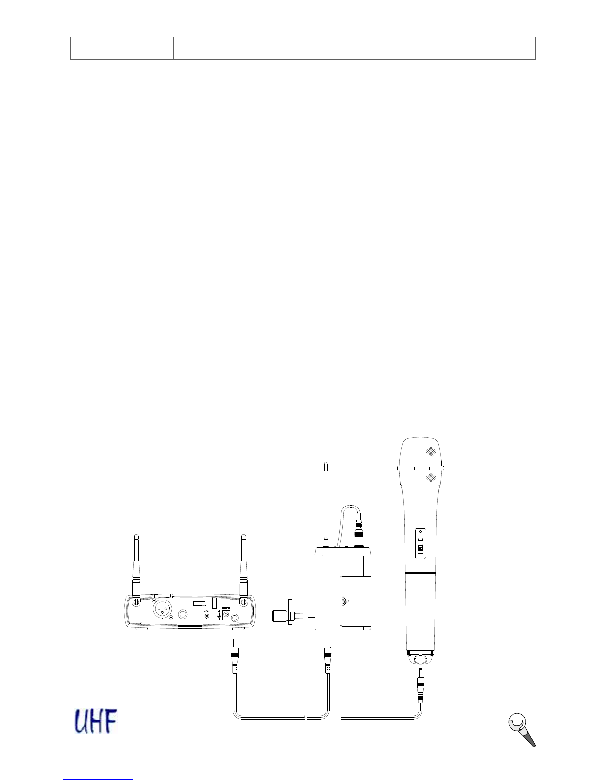
7.5 Setting up thebodypack transmitter
A. Connectinga microphone
ØOpen the battery cover.PushtheMIC/LINE switch to “MIC”and use the supplied screw-
driver to adjust the GAIN at appropriate position.
ØPlug the mini XLR connector (3.5jplug) of the microphone cableintothe audioinput
connector on the bodypack transmitter.
ØSwitch the transmitter andhi-fiappliance (amplifier, tape deck etc.) power on.
ØTest the microphone and adjust the levels onyour mixer or amplifier.
B. Connectingan instrument
ØOpen the battery cover. PushtheMIC/LINE switch to “LINE”and use the supplied
screwdriver to adjust the GAIN at appropriate position.
ØPlug the 6.3jphoneplug of theoptional guitar cable totheoutput jack on the instrument and
the mini XLR (3.5jplug) into audio input connector on the bodypack transmitter.
ØSwitch the transmitter andhi-fiappliance (amplifier, tape deck etc.) power on.
ØPlay theinstrument for testingand adjust the levels on your mixer or amplifier.
MIC/LINE switchisan optional function only for use with mini XLR connector.
8. Trouble-shooting
Problem Solution
No sound äCheck the power supply of themicrophone and receiver.
äCheck that the transmitter and receiver are tuned to the same
frequency.
äCheck whether the hi-fiappliance is switched on and the receiver
output is connected to audio mixer or amplifier input.
äCheck whether transmitter is toofar away fromreceiver or SQUELCH
control set toohigh.
äCheck whether receiver is located too near metalobject or there are
obstructions between transmitter and receiver.
Sound interference äCheck the antenna location.
äWhen using 2or above microphone sets simultaneously, makesure
that the chosenfrequencies arenot interfered.
äCheck whether the interference comes fromother wireless
microphones, TV, radio andetc.
Distortion äCheck the receiver volume level is set too highor toolow.
äCheck whether the interference comes fromother wireless
microphones, TV, radio andetc.
Wireless Microphone

WIRELESS FEATURES & SPECIFICATIONS
9. System Feature
ØOperating in UHFband frequency with synthesizer controlled.
ØThe wireless microphone system with 16 or 64 selectable frequencies via PhaseLocked
Loop (PLL) circuitry makes it easy to choose non-interfered channels.
ØSuper high sensitivity, extremely low noise transmissionand reception.
ØSMT assembled PCB module ensures thequality andstability.
10. SystemSpecification
Receiver
ØCarrier Frequency Range : UHF band 682~806MHz
ØFrequency Stability : ±0.005%
ØS/N ratio : >94dB, at 48KHz deviationand 60dBmV antenna input
ØMaximum Deviation : ±48KHz
ØImage and Spurious Rejection
:80 dB minimum
ØReceiving Sensitivity : 6 dBμV.
ØSelectivity : >50dB
ØAF Response : 50Hz to15KHz (±3dB)
ØT.H.D. : <1% (at 1KHz)
ØAudio Output : Balanced andunbalanced audiooutputs
ØCurrent consumption : 250mA ±10mA,
ØPower Supply : 12V DC
ØDimensions : 156(W)x140(D) X41(H) mm
Handheld/Bodypack Transmitter
ØCarrier Frequency Range : UHF band 682~806MHz
ØRF Power Output : 10mW (max.)
ØOscillation Mode : PLLsynthesized
ØFrequency Stability : ±0.005%
ØMaximum Deviation : ±48KHz
ØSpurious Emission : >60dB belowcarrier frequency
ØT.H.D. : <1% (at 1KHz)
ØMicrophone Capsule : Handheld:uni-directional dynamic or uni-directional electret
condenser unit
Lavalier:uni-directional electret condenser unit
ØOperating voltage : DC1.5V x2 AA size dry or rechargeable batteries
ØCurrent consumption : 65mA ±5mA
ØOperating Time : 20 hours (1300mA dry or rechargeable batteries)
ØDimension(mm) : Handheld: 55jx267mm
Bodypack:64(W)x97(H)x24(D)
9
Wireless Microphone
Table of contents
Other MASCOT Microphone System manuals