manuals.online logo
Brands
  1. Home
  2. •
  3. Brands
  4. •
  5. Mase Generators
  6. •
  7. Portable Generator
  8. •
  9. Mase Generators VOYAGER 8000 DM User manual

Mase Generators VOYAGER 8000 DM User manual

MANUALE D'INSTALLAZIONE
INSTALLATION MANUAL
MANUEL D' INSTALLATION
EINRICHTGHANDBUCH
MANUAL DELLA INSTALACIÒN
Rev. 0 - COD. 41111
VOYAGER 8000 DM
VOYAGER 9000 DT
VOYAGER 9000 DM
VOYAGER 10000 DT
mase
GENERATORS
2
INDICE - INDEX
1. INSTALLAZIONE ................................ 4
1.1 Caratteristiche ................................... 4
1.2 Ventilazione ....................................... 4
1.3 Vano di alloggio
e osizionamento del gru o ........ 6
1.4 Collegamento marmitta
e silenziatore .................................... 8
1.5 Kit silenziatore (o tional) .............. 10
1.6 Montaggio collettore scarico
(o tional) ......................................... 10
2. CIRCUITO DI RAFFREDDAMENTO 12
2.1 Descrizione ...................................... 12
2.2 Riem imenti e rabbocchi .............. 12
3. CIRCUITO COMBUSTIBILE ............ 16
3.1 Descrizione ...................................... 16
3.2 Collegamento .................................. 16
3.3 Disareazione im ianto ................... 18
4. COLLEGAMENTI ELETTRICI .......... 20
4.1 Premessa ......................................... 20
4.2 Allacciamento batteria ................... 20
4.3 Allacciamento annello comandi . 22
4.4 Collegamento degli utilizzi ............ 26
4.5 Collegamento di messa a terra .... 28
1. INSTALLATION .................................. 4
1.1 Features ............................................. 4
1.2 Ventilation .......................................... 4
1.3 Generator housing
and positioning.................................6
1.4 xhaust
and silcencer connection ................ 8
1.5 Silencer kit (optional) .................... 10
1.6 Fitting and optiona exhaust
manifold ........................................... 10
2. COOLING CIRCUIT .......................... 12
2.1 Description ...................................... 12
2.2 Filling and topping up ...................12
3. FU L CIRCUIT .................................16
3.1 Description ...................................... 16
3.2 Connection ...................................... 16
3.3 System deaeration .........................18
4. POW R CONN CTION ................... 20
4.1 Introduction .....................................20
4.2 Battery connection ......................... 20
4.3 Control panel connection .............. 22
4.4 Appliance connection .................... 26
4.5 arthing ........................................... 28
3
INDICE - INDEX
1. INSTALLATION ........ 5
1.1 Caracteristiques ...... 5
1.2 Ventilation ................ 5
1.3 Logement et
positionnement
du groupe ................ 7
1.4 Branchement pot
dechappement et
silencieux ................ 9
1.5 Kit silencieux
(en option) ............. 11
1.6 Montage collecteur
echappement
(en option) ............. 11
2. CIRCUIT D
R FROIDIS-
S M NT ................. 13
2.1 Description ............ 13
2.2 Remplissage et
remises a niveau .. 13
3. CIRCUIT
COMBUSTIBL ..... 17
3.1 Description ............ 17
3.2 Branchement ......... 17
3.3 Desaeration
installation ............. 19
4. BRANCH M NTS
L CTRIQU S ...... 21
4.1 Avant-propos ......... 21
4.2 Branchement
batterie ................... 21
4.3 Branchement pupitre
de commandes ..... 23
4.4 Branchements
des utilisations ..... 27
4.5 Branchement de
mise à la terre ...... 29
1. INSTALLATION ........ 5
1.1 Merkmale ................. 5
1.2 Belüftung ................. 5
1.3 Installationsraum und
Anordung des
Aggregates .............. 7
1.4 Anschluss von
Asupufftopf und
Schalldämpfer ......... 9
1.5 Schalldämpfer-Kit
(auf wunsch) ......... 11
1.6 Montage des zusatz-
auspuffkrümmers . 11
2. KÜHLKR ISLAUF .. 13
2.1 Beschreibung ........ 13
2.2 Füllen und
Nachfüllen ............. 13
3. KRAFTSTOFF-
KR ISLAUF ........... 17
3.1 Beschreibung ........ 17
3.2 Anschluss .............. 17
3.3 ntlüftung
der Anlage ............. 19
4. L KTRO-
ANSCHLÜSS ....... 21
4.1 Vorbemerkung ....... 21
4.2 Batterieanschluss . 21
4.3 Alle Kontrol-,
Start- und Aus-
Schaltfunktionen ... 23
4.4 Anschluss der
Verbraucher........... 27
4.5 rdanschluss ........ 29
1. INSTALACION .......... 5
1.1 Características ........ 5
1.2 Ventilación ............... 5
1.3 Compartimiento de
instalación y
posicionamiento
de la unidad ............ 7
1.4 Conexión del
silenciador y del
silenciador
accesorio ................. 9
1.5 Kit silenciador
(opcional)............... 11
1.6 Montaje del colector
opcional de
descarga ................ 11
2. CIRCUITO D
NFRIAMI NTO .... 13
2.1 Descripción ........... 13
2.2 Llenado del circuito
y sucesivos
rellenos .................. 13
3. CIRCUITO D L
COMBUSTIBL ..... 17
3.1 Descripción ........... 17
3.2 Conexiones ............ 17
3.3 liminación del aire
en el sistema ........ 19
4. CON XION S
L CTRICAS ......... 21
4.1 Premisa .................. 21
4.2 Conexión de la
batería .................... 21
4.3 Conexión del panel
de mandos ............ 23
4.4 Conexión de los
dispositivos utilizado-
res de corriente .... 27
4.5 Conexión de contacto
a tierra ................... 29
4
1. INSTALLATION
1.1 FEATURES
The VOYAGER is a generator designed to be
installed in motor vehicles, but which can also be
used in a fixed location, taking care that the
cooling air vents are never blocked
The degree of protection against water or intrusion
of foreign bodies corresponds to IP34, so the
generator can be used outdoors or in the presence
of water spray or rain VOYAGER is equipped
with a liquid-cooled diesel motor, complete with
fuel pump and filter system
The generator is connected to a control panel
which can be installed inside the motor vehicle
This controls start - stop and safety devices.
1.2 VENTILATION
The VOYAGER generator has an internal forced-
air and liquid cooling system The air, required for
cooling and combustion, is sucked up inside the
soundproof casing (Fig 1 Ref 1) through two
different vents - one on the door (Fig 1 Ref 3)
and another on the rear of the casing (Fig 2 Ref
6) - and is expelled through the expulsion vent on
the door (Fig 1 Ref 4) To ensure correct
generator operation, it is important that these air
vents are never blocked or close to hear sources
1. INSTALLAZIONE
1.1 CARATTERISTICHE
Il VOYAGER è un gruppo elettrogeno progettato
per essere installato a bordo di autoveicoli, ma
pu tuttavia essere utilizzato in postazione fissa
avendo cura di lasciare libere le aperture di
aspirazione e scarico dellaria di raffreddamento.
Il grado di protezione contro lacqua e lintrusione
di corpi estranei è corrispondente a IP34, il quale
consente luso del gruppo allaperto ed in presen-
za di spruzzi dacqua e pioggia. Le motorizzazio-
ni impiegate sono diesel, raffreddate a liquido,
complete di pompa carburante e sistemi filtranti.
Il gruppo è collegato ad un pannello comandi,
che pu essere installato allinterno dellautomez-
zo, il quale gestisce le funzioni di avviamento -
arresto e le protezioni di sicurezza.
1.2 VENTILAZIONE
Il gruppo elettrogeno VOYAGER è dotato di un
sistema interno di raffreddamento a liquido ed
aria forzata. Laria, necessaria al raffreddamento
ed alla combustione, è aspirata allinterno della
cassa insonorizzante (fig.1 rif. 1) attraverso due
differenti griglie: una posta sul portello di chiusu-
ra (fig.1 rif. 3 ), ed una seconda posta sul lato
posteriore della cassa (fig. 2 rif. 6) ed è espulsa
attraverso la griglia di scarico posta sul portello
di chiusura (fig.1 rif. 4). E di estrema importanza,
per il buon funzionamento del gruppo, che le
griglie di aspirazione e scarico siano sempre ben
libere e lontane da fonti di calore.
Fi . 1 Fi . 1
5
1. INSTALLATION
1.1 ERK ALE
VOYAGER ist ein Generator,
der für die Montage in
Automobilen konstruiert wurde,
er kann jedoch auch an einem
festen Ort installiert werden
Dabei ist allerdings darauf zu
achten, daß die Ansaug- und
Auslaßöffnungen für die Kühlluft
nicht versperrt werden Der
Schutz gegen das Eindringen
von Wasser und Fremdkörpern
entspricht der Schutzart IP34
und ermöglicht die Benutzung
des Aggregates im Freien, auch,
wenn es dort Spritzwasser und
Regen ausgesetzt ist Betrieben
wird es mit flüssigkeitsgekühlten
Dieselmotoren mit Kraftstoff-
pumpe und Filtersystemen
Am Aggregat ist eine Bedientafel
angeschlossen, die im Inneren
des Wagens installiert werden
kann, und die die Funktionen
Start - Stop und die
Schutzfunktionen handhabt.
1.2 BELÜFTUNG
Der VOYAGER-Generator ist
mit einem internen Flüssigkeits-
und Luftleit-Kühlsystem
ausgestattet Die zur Kühlung
und für die Verbrennung
notwendige Luft wird durch zwei
verschiedene Roste in das
schallgedämpfte Gehäuse (Abb
1, Pos 1) gesaugt: einer
befindet sich an der
Verschlußklappe (Abb 1, Pos
3), und ein zweiter sitzt an der
Hinterseite des Gehäuses (Abb
2, Pos 6); die Abluft wird durch
den Abluftrost an der
Verschlußklappe (Abb 1, Pos
4) abgeleitet Für das ordnungs-
gemäße Funktionieren des
Aggregates ist es außerord-
entlich wichtig, daß die Ansau-
groste und der Abluftrost immer
frei sind und sich nicht in der
Nähe von Wärmequellen
befinden
1. INSTALACION
1.1 CARACTERÍSTICAS
La VOYAGER es una unidad
electrógena proyectada para ser
instalada a bordo de vehículos
pero puede ser también utilizada
en posición fija, cuidando dejar
libres las aberturas de aspiración
y descarga del aire de
enfriamiento
El grado de protección contra el
agua y la entrada de cuerpos
extraños corresponde a IP34, lo
que permite el uso de la unidad
al aire libre y en presencia de
chorros de agua y de lluvia Los
motores empleados son diesel,
enfriados mediante líquido, con
bomba de carburante y sistemas
de filtración
La unidad está conectada a un
panel de mandos que puede ser
instalado al interior del vehículo
y que permite gobernar las
funciones de arranque - parada
y las protecciones de
seguridad
1.2 VENTILACIÓN
La unidad electrógena
VOYAGER dispone de un siste-
ma interno de enfriamiento me-
diante líquido y aire de circu-
lación forzada El aire, necesario
para el enfriamiento y la combu-
stión, es aspirado al interior de
la caja insonorizante (fig 1 ref 1)
a través de dos diferentes rejil-
las, una situada en la portezuela
de cierre (fig 1 ref 3) y la segun-
da instalada en la parte posterior
de la caja (fig 2 ref 6); el aire es
expulsado a través de la rejilla
de descarga situada en la
portezuela de cierre (fig 1 ref 4)
Para un adecuado funciona-
miento de la unidad es de
fundamental importancia que las
rejillas de aspiración y descarga
se encuentren siempre libres de
todo obstáculo y en posición
alejada de fuentes de calor
1. INSTALLATION
1.1 CARACTERISTIQUES
VOYAGER est un groupe
électrogène conçu pour être
installé à bord des véhicules
automobiles, toutefois, il peut
aussi être utilisé dans un
emplacement fixe en prenant
soin de laisser les ouvertures
daspiration et dévacuation de
lair de refroidissement libres
Le degré de protection IP34
contre leau et lintroduction de
corps étrangers permet lutili-
sation du groupe en plein air et
en présence décla-boussures
deau et de pluie Les moto-
risations utilisées sont diesel,
refroidies par liquide, complétées
de pompe carburant et de
systèmes filtrants
Le groupe est relié à un pupitre
de commandes qui peut être
installé à lintérieur du véhicule,
ce groupe gère les fonction de
démarrage - arrêt ainsi que
les protections de sécurité.
1.2 VENTILATION
Le groupe électrogène
VOYAGER est doté dun
système interne de refroidis-
sement par liquide et à air forcé
Lair nécessaire au refroidis-
sement et à la combustion est
aspiré à lintérieur du carénage
insonorisant (Fig 1 Réf 1) à
travers deux grilles différentes :
une première située sur le
portillon de fermeture (Fig 1 Réf
3) et une seconde située sur le
côté arrière du carénage (Fig 2
Réf 6) et expulsé à travers la
grille dévacuation située sur le
portillon de fermeture (Fig Réf
4) Pour le bon fonctionnement
du groupe, il est extrêmement
important que les grilles daspi-
ration et dévacuation soient
toujours libres et éloignées de
toute source de chaleur

6
IMPORTANTE
Laria di raffreddamento del ruppo può
contenere as nocivi e perciò non deve mai
essere utilizzata per riscaldare ambienti
abitabili. Si consi lia di si illare il vano
dinstallazione in modo da impedire infiltra-
zioni di vapori o as nellarea abitata.
1.3 VANO DI ALLOGGIO E
POSIZIONAMENTO DEL GRUPPO
Il vano, in cui andrà posizionato il gruppo elettro-
geno VOYAGER, dovrà essere sufficientemente
ampio, in modo da consentire un agevole inseri-
mento del gruppo.
Le dimensioni del gruppo sono riportate in Fig.
2; la parte inferiore dovrà prevedere degli appog-
gi portanti sui quali va appoggiato il gruppo.
Sulla parte inferiore del vano, se non è in diretta
comunicazione con lesterno, dovrà essere rica-
vata unapertura che permetta lentrata dellaria
attraverso la griglia posteriore della casa (fig. 1
rif. 6)
Sulle due parti laterali del gruppo (Fig. 1 rif. 2 e
7) si trovano i punti di ancoraggio da utilizzare
per fissare il gruppo alla base del vano di allog-
gio. Il vano di alloggio deve inoltre prevedere
delle aperture che permettano il passaggio: dei
fili elettrici di collegamento, delle tubazioni del
carburante e del tubo di collegamento della mar-
mitta.
Il volume del vano, che accoglie la marmitta sul
lato posteriore del gruppo, non è necessario
qualora la marmitta venga portata a distanza.
(Fig. 4)
I PORTANT
The generator cooling air can contain
harmful gases and must never be used to
heat living environments. It is best to seal
the generator housing in order to avoid the
infiltration of fumes or gases.
1.3 GENERATOR HOUSING
AND POSITIONING
The housing for the VOYAGER generator should
be sufficiently large for the unit to fit in easily
Generator dimensions are shown in Fig 2; the
lower part of the housing must be provided with
supports for the generator If there is no direct
passage between the lower part of the housing
and the outer environment, then an opening will
have to be made to enable air to pass through
the rear grating (Fig 1 Ref 6)
On the two sides of the generator (Fig 1 Ref 2
and 7) are the anchor points to be used to fix the
generator to the floor of the housing The housing
must also be equipped with openings for: the
power leads, the fuel pipes and the exhaust pipe
The part of the housing set aside for the exhaust
at the back of the generator will not be required
if the exhaust is positioned at a distance (Fig 4)
7
I PORTANT
Lair de refroidissement du
groupe peut contenir des
gaz nocifs, par conséquent,
il ne doit jamais être utilisé
pour réchauffer des pièces
habitables. Il est conseillé
de sceller le logement
dinstallation de façon à
empêcher les infiltrations
de vapeur ou de gaz dans
la zone habitée.
1.3 LOGE ENT ET
POSITIONNE ENT DU
GROUPE
Le logement dans lequel le
groupe électrogène VOYAGER
sera positionné devra être
suffisamment vaste, de façon à
permettre une introduction aisée
du groupe
Les dimensions du groupe sont
indiquées Fig 2; la partie
inférieure devra être dotée
dappuis portants sur lesquels
le groupe sera posé Si la partie
inférieure du logement ne
communique pas directement
avec lextérieur il est nécessaire
de réaliser une ouverture
permettant lentrée de lair à
travers la grille postérieure (Fig
1 Réf 6)
Sur les deux parties latérales
du groupe (Fig 1 Réf 2 et 7)
se trouvent les points dancrage
à utiliser pour fixer le groupe à
la base du logement De plus,
la zone logement doit être dotée
douvertures permettant le
passage des fils électriques de
branchement, des tuyaux du
carburant et du tuyau de liaison
du pot déchappement
Le volume du logement qui
accueille le pot déchappement
à larrière du groupe nest pas
nécessaire si le pot
déchappement est installé à
distance (Fig 4)
WICHTIG
Die Kühlluft des Aggregates
kann gesundheitsschädli-
che Gase enthalten und darf
daher nie für die Beheizung
von Wohnräumen
verwendet werden. Es wird
empfohlen, den Raum, in
dem es installiert wurde, so
zu versiegeln, daß keine
Dämpfe oder Gase in den
Wohnbereich gelangen
können.
1.3 INSTALLATIONSRAU
UND ANORDNUNG DES
AGGREGATES
Der Raum, in dem der
VOYAGER-Generator
untergebracht wird, muß so groß
sein, daß das Aggregat dort
bequem installiert werden kann
Die Abmessungen des
Aggregates werden in Abb 2
wiedergegeben; im unteren
Bereich müssen Stützen
vorgesehen werden, auf denen
das Aggregat aufliegen kann
Im unteren Bereich des Raumes
muß, wenn er keine direkte
Verbindung nach außen hat,
eine Öffnung angebracht
werden, die das Einströmen von
Luft durch den hinteren Rost
(Abb 1, Pos 6) ermöglicht
An den beiden Seitenteilen des
Aggregats (Abb 1, Pos 2 und
7) befinden sich
Verankerungspunkte, die zur
Befestigung des Aggregats am
Boden des Installationsraumes
dienen Der Installationsraum
muß außerdem Öffnungen als
Durchgang für elektrische
Anschlußkabel,
Kraftstoffleitungen und für das
Auspuffrohr haben
Raum für den Auspufftopf hinten
am Aggregat ist nicht
erforderlich, wenn der Auspuff
weiter weg geführt wird (Abb
4)
I PORTANTE
El aire de enfriamiento de
la unidad puede contener
gases nocivos, motivo por
el cual no deberá ser nunca
utilizado para la calefacción
de ambientes habitados. Es
conveniente sellar el com-
partimiento de instalación
a fin de impedir filtraciones
de vapores o gases hacia
zonas habitadas.
1.3 CO PARTI IENTO DE
INSTALACIÓN Y
POSICIONA IENTO DE
LA UNIDAD
El compartimiento en el cual
será instalada la unidad
electrógena VOYAGER deberá
ser suficientemente amplio a fin
de permitir una fácil instalación
Las dimensiones de la unidad
son indicadas en la fig 2; la par-
te inferior deberá disponer de
adecuados soportes (sobre los
cuales deberá ser apoyada la
unidad) y, en caso de no
encontrarse directamente
comunicada con el exterior, en
ella deberá ser predispuesta una
abertura que permita la entrada
del aire a través de la rejilla
posterior (fig 1 ref 6)
En ambos costados de la unidad
(fig 1 ref 2 y 7) existen puntos
de anclaje, a utilizar para fijar la
unidad a la base del
compartimiento de instalación
Además este compartimiento
debe disponer de aberturas que
permitan el paso de los cables
eléctricos de conexión, de los
tubos del carburante y del tubo
de conexión del silenciador
El espacio que se requiere para
la instalación del silenciador en
la parte posterior de la unidad
no será necesario en caso de
que el silenciador sea instalado
a distancia (fig 4)
8
1.4 COLLEGAMENTO MARMITTA
E SILENZIATORE
Il gruppo viene fornito con una marmitta, una
staffa ed una fascetta.La marmitta pu essere
montata posteriormente alla cassa utilizzando
lapposita staffa, in dotazione, per il suo ancorag-
gio. Come indicato alla fig. 2 la marmitta pu
essere orientata in quatto direzioni per soddisfare
le varie esigenze dinstallazione.
Per il posizionamento della marmitta sulla parte
inferiore del gruppo (fig. 3) è previsto un colletto-
re OPTIONAL orientato verso il basso da sosti-
tuire allo standard. Sul fondo della cassa sono
presenti i fori di fissaggio della marmitta con la
staffa fornita di serie.
Se particolari esigenze dinstallazione lo richedono,
è possibile portare a distanza la marmitta (fig. 4),
e per un maggior abbattimento del rumore emes-
so allo scarico, si pu collegare in serie, tramite
un tubo flessibile di acciaio (fig. 2 rif. 2), un
silenziatore (fig. 2 rif. 1). A tale scopo stato
previsto un kit SILENZIATORE (OPTIONAL) che
permette la realizzazione delle varie configura-
zioni possibili dello scarico.
1.4 EXHAUST AND SILENCER CONNECTION
The generator is equipped with an exhaust, a
bracket and a clamp The exhaust can be fitted
at the back of the casing using the bracket
provided As shown in Fig 2, the exhaust can be
turned in four different directions to meet various
installation needs
To position the exhaust in the lower part of the
generator (Fig 3), an OPTIONAL manifold can
be supplied which is turned downwards This
replaces the standard manifold On the bottom of
the casing are the holes for securing the exhaust
using the bracket provided
For special types of installation, the exhaust can
be fitted at a distance (Fig 4) and to lower noise
levels, a silencer (Fig 2 Ref 1) can be fitted, in
series, using a flexible steel pipe (Fig 2 Ref 2)
For this purpose an (OPTIONAL) SILENCER kit
is available for implementing the various exhaust
configurations
Fi . 2 Fi . 3
9
1.4 BRANCHE ENT POT
DECHAPPE ENT ET
SILENCIEUX
Le groupe est équipé dun pot
déchappement, dune bride et
dun collier Le pot
déchappement peut être monté
à larrière du carénage en
utilisant la bride appropriée en
dotation pour sa fixation
Comme indiqué Fig 2, le pot
déchappement peut être orienté
dans quatre directions afin de
satisfaire les différentes
exigences dinstallation
Pour le positionnement du pot
déchappement sur la partie
inférieure du groupe (Fig 3) un
collecteur orienté vers le bas
remplaçant le collecteur stan-
dard peut être fourni EN
OPTION Sur le fond du
carénage se trouvent les orifices
de fixation avec la bride fournie
de série
En cas dexigences dinstallation
particulières, il est possible
dinstaller le pot déchappement
à distance (Fig 4) et, afin de
diminuer le bruit émis par
léchappement, il est possible
de brancher, en série, un
silencieux (Fig 2 Réf 1) au
moyen dun tuyau flexible en
acier (Fig 2 Réf 2)
Dans ce but, un kit SILENCIEUX
(EN OPTION) est prévu afin de
permettre la réalisation des
différentes configurations
déchappement possibles
1.4 ANSCHLUSS VON
AUSPUFFTOPF UND
SCHALLDÄ PFER
Das Aggregat wird geliefert mit
einem Auspufftopf, einem Bügel
und einer Schelle Der
Auspufftopf kann mit Hilfe des
zugehörigen Bügels, der zur
Verankerung mitgeliefert wird,
hinten ans Gehäuse montiert
werden Wie in Abb 2
dargestellt, kann der Auspufftopf
in vier verschiedene Richtungen
gedreht werden, um den
unterschiedlichen Installation-
serfordernissen entgegenzu-
kommen
Für das Anbringen des
Auspufftopfes am unteren Teil
des Aggregates (Abb 3) kann
AUF WUNSCH ein nach unten
gerichteter Auspuffkrümmer
geliefert werden, der anstelle
des Standardkrümmers
verwendet wird Am
Gehäuseboden befinden sich
Befestigungsbohrungen für den
Auspufftopf mit serienmäßig
geliefertem Bügel
Wenn es die Installation
erfordert, kann der Auspufftopf
(Abb 4) in einer gewissen
Entfernung montiert werden, und
zur besseren Dämpfung des am
Auspuff entstehenden
Geräusches kann dahinter über
einen Stahlschlauch (Abb 2,
Pos 2) ein Schalldämpfer (Abb
2, Pos 1) angeschlossen
werden Dazu kann AUF
WUNSCH ein
SCHALLDÄMPFER-Kit geliefert
werden, mit dessen Hilfe die
verschiedenen Anordnungen
des Auspuffes durchgeführt
werden können
1.4 CONEXIÓN DEL
SILENCIADOR Y DEL
SILENCIADOR
ACCESORIO
La unidad está provista de un
silenciador, un soporte y una
abrazadera El silenciador puede
ser instalado en la parte
posterior de la caja mediante el
soporte predispuesto para su
fijación Tal como está indicado
en la fig 2, el silenciador puede
ser orientado en cuatro
diferentes direcciones, según
cuáles sean las exigencias de
instalación
Para la instalación del silen-
ciador, en la parte inferior de la
unidad (fig 3) ha sido previsto
un colector OPCIONAL orien-
tado hacia abajo, el que susti-
tuye el colector estándar En el
fondo de la caja existen orificios
destinados a permitir la fijación
del silenciador mediante el
soporte suministrado de serie
En el caso de situaciones
particulares de instalación, será
posible colocar el silenciador a
distancia (fig 4) y, a fin de
obtener una reducción del ruido
producido por el escape, será
posible conectar en serie un
silenciador opcional (fig 2 ref 1),
mediante un tubo flexible de
acero (fig 2 ref 2) Para este
objeto ha sido previsto un kit
SILENCIADOR (OPCIONAL),
que permitirá elegir la aplicación
más adecuada entre las dife-
rentes posibles configuraciones
del escape
10
1.5 KIT SILENZIATORE (OPTIONAL)
Il kit comprende: un silenziatore, una staffa per il
fissaggio della marmitta, un tubo flessibile lungo
m. 2, una curva, n. 3 fascette. (Fig. 5)
1.5 SILENCER KIT (OPTIONAL)
The kit includes: a silencer, a bracket for fitting
the exhaust, a flexible pipe 2 metres long, an
elbow, 3 clamps (Fig 5)
Fi . 4 Fi . 5
Fi . 6
1.6 MONTAGGIO COLLETTORE SCARICO
OPTIONAL
Come descritto al paragrafo d), è disponibile un
collettore di scarico, da sostituire allo standard
(fig. 6 rif. 1), per posizionare la marmitta sulla
parte inferiore del gruppo. Per eseguire tale
sostituzione, è necessario rimuovere il portello di
chiusura posteriore della cassa. Eseguita tale
operazione, si accede con grande facilità alle viti
che fissano il collettore standard al motore.
Rimuovere le viti di fissaggio (fig. 6 rif. 3). e
scollegare il collettore di scarico. Riposizionare il
nuovo collettore (fig. 6 rif. 2) e rimontare una
nuova guarnizione di tenuta qualora risultasse
danneggiata; serrare con cura le viti di fissaggio
e richiudere il portello posteriore.
1.6 FITTING THE OPTIONAL EXHAUST
ANIFOLD
As mentioned at paragraph d), an exhaust
manifold is available to replace the standard
model (Fig 6 Ref 1) so the exhaust can be fitted
to the lower part of the generator To carry out
this replacement, it will be necessary to remove
the rear door of the casing Once this door has
been removed, the screws fastening the stan-
dard manifold to the motor are easily accessible
Remove these screws (Fig 6 Ref 3) and the
exhaust manifold Fit the new manifold (Fig 6
Ref 2) and refit a new gasket if the old one is
damaged Carefully fasten the screws and replace
the rear door
11
1.5 KIT SILENCIEUX
(EN OPTION)
Le kit comprend : un silencieux,
une bride pour la fixation du pot
déchappement, un tuyau flexible
dune longueur de 2 m , un
coude, 3 colliers (Fig 5)
1.6 ONTAGE
COLLECTEUR
ECHAPPE ENT
(EN OPTION)
Comme décrit au paragraphe
d), un collecteur déchappement
est disponible, en remplacement
du collecteur standard (Fig 6
Réf 1), afin de positionner le
pot déchappement sur la partie
inférieure du groupe Pour
effectuer ce remplacement, il est
nécessaire dôter le portillon de
fermeture postérieur du
carénage Une fois cette
opération effectuée, on accède
très facilement aux vis qui fixent
le collecteur standard au moteur
Enlever les vis de fixation (Fig
6 Réf 3) et ôter le collecteur
déchappement
Positionner le nouveau collec-
teur (Fig 6 Réf 2) et monter un
nouveau joint détanchéité si
celui-ci est endommagé; serrer
soigneusement les vis de
fixation et refermer le portillon
postérieur
1.5 SCHALLDÄ PFER-KIT
(AUF WUNSCH)
Zum Kit gehören: ein
Schalldämpfer, ein
Befestigungsbügel für den
Auspufftopf, ein Schlauch von 2
m Länge, ein Krümmer, 3
Schellen (Abb 5)
1.6 ONTAGE DES
ZUSATZ-
AUSPUFFKRÜ ERS
Wie in Abschnitt d) erwähnt
wurde, kann der Standard-
krümmer (Abb 6, Pos 1) durch
einen anderen Auspuffkrümmer
ersetzt werden, um den
Auspufftopf unten am Aggregat
anzubringen Um dies tun zu
können, muß die hintere
Verschlußklappe am Gehäuse
entfernt werden Danach sind
die Schrauben, mit denen der
Standardkrümmer am Motor
befestigt sind, sehr leicht
erreichbar Nun die
Befestigungsschrauben
entfernen (Abb 6, Pos 3) und
den Auspuffkrümmer
abnehmen Den neuen
Krümmer ansetzen (Abb 6, Pos
2) und eine neue Dichtung
anbringen, falls die alte
beschädigt wurde; die
Befestigungsschrauben fest
anziehen und die Hinterklappe
schließen
1.5 KIT SILENCIADOR
(OPCIONAL)
El kit comprende: un silenciador,
un soporte de fijación, un tubo
flexible de 2 m de longitud, una
curva y tres abrazaderas (fig 5)
1.6 ONTAJE DEL
COLECTOR OPCIONAL
DE DESCARGA
Tal como ha sido indicado en la
precedente letra d), se
encuentra disponible un colector
de descarga que puede sustituir
a aquél estándar (fig 6 ref 1)
para instalar el silenciador en la
parte inferior de la unidad Para
efectuar esta sustitución es
necesario remover la portezuela
de cierre posterior de la caja
Una vez efectuada esta
operación se obtiene fácil acce-
so a los tornillos que fijan el
colector estándar al motor
Retirar los tornillos de fijación
(fig 6 ref 3) y desconectar el
colector de descarga Instalar
el nuevo colector (fig 6 ref 2) y
eventualmente sustituir la junta
de retención en caso de estar
dañada; apretar cuidado-
samente los tornillos de fijación
y cerrar la portezuela posterior
12
2. CIRCUITO
DI RAFFREDDAMENTO
2.1 DESCRIZIONE
Sul gruppo elettrogeno VOYAGER è utilizzato
un motore diesel raffreddato a liquido con radia-
tore installato allinterno della cassa, completo di
vaso di espansione ed elettroventole. Per il
riempimento del circuito di raffreddamento e gli
eventuali rabbocchi, va utilizzata una miscela di
acqua e antigelo in proporzioni del 50%.
2.2 RIEMPIMENTO E RABBOCCHI
Il gruppo viene fornito col radiatore e il circuito
di raffreddamento privo di liquido refrigerante,
perci , ad installazione eseguita e prima di avvia-
re il gruppo, si deve procedere ad effettuare un
completo riempimento.
Per facilitare tale operazione, è possibile estrarre
il radiatore dallinterno della cassa facendolo slit-
tare verso lesterno e introdurre il liquido refrige-
rante dal bocchettone di riempimento (fig. 7 rif.
4). Per rendere possibile lestrazione del radia-
tore è necessario, prima di tutto, rimuovere le viti
che lo tengono vincolato ( fig. 7 rif. 3), quindi
tirarlo con decisione verso lesterno facendolo
slittare sulla guida di sostegno (fig. 7 rif. 5).
Terminata loperazione di riempimento riportare il
radiatore alla posizione iniziale riavvitando con
cura le viti.
2. COOLING CIRCUIT
2.1 DESCRIPTION
The VOYAGER generator is equipped with a
liquid-cooled diesel motor with radiator installed
inside the casing, complete with expansion tank
and electric fan The cooling circuit must be filled
and, if necessary, topped up with a 50/50 ratio of
water and antifreeze
2.2 FILLING AND TOPPING UP
The generator is supplied with radiator and cooling
circuit without coolant Once installation has been
completed, before starting the generator, make
sure the cooling circuit is filled
To facilitate this operation, it is possible to remove
the radiator from inside the casing by sliding it
out This can be subsequently filled with coolant
through the filler (Fig 7 Ref 4) To make possible
the removal of the radiator, it will first of all be
necessary to remove the screws which hold it in
place (Fig 7 Ref 3) and subsequently slide it
outwards on the support guide (Fig 7 Ref 5)
After filling, replace the radiator and fasten in
place with screws
Fi . 7
13
2. CIRCUIT DE
REFROIDISSEMENT
2.1 DESCRIPTION
Sur le groupe VOYAGER est
utilisé un moteur diesel refroidi
par liquide avec radiateur installé
à lintérieur du carénage,
complété de vase dexpansion
et délectro- ventilateur En ce
qui concerne le remplissage du
circuit de refroidissement ainsi
que les éventuelles remises à
niveau, il est nécessaire dutiliser
un mélange deau et dantigel,
dans un rapport de 50%
2.2 RE PLISSAGE ET
RE ISES A NIVEAU
Le groupe est fourni avec le
radiateur et le circuit de
refroidissement sans liquide
réfrigérant, par conséquent, une
fois linstallation terminée, avant
de démarrer le groupe, il est
nécessaire de procéder au
remplissage complet
Afin de faciliter cette opération,
il est possible dextraire le
radiateur de lintérieur du
carénage en le faisant glisser
vers lextérieur puis dintroduire
le liquide réfrigérant par lorifice
de remplissage (Fig 7 Réf 4)
Pour que lextraction du
radiateur soit possible, il est
avant tout nécessaire dôter les
vis qui le maintiennent (Fig 7
Réf 3) puis de le tirer
fermement vers lextérieur en le
faisant glisser sur le guide de
soutien (Fig 7 Réf 5) Une fois
lopération de remplissage
terminée, replacer le radiateur
dans sa position initiale et fixer
de nouveau les vis avec soin
2. KÜHLKREISLAUF
2.1 BESCHREIBUNG
Beim VOYAGER-Generator wird
ein flüssigkeitsgekühlter Diesel-
motor verwendet, wobei der
Kühler mit Überlaufgefäß und
Elektro-Lüfterrad im Gehäus-
einnern untergebracht ist
Gefüllt, und eventuell nach-
gefüllt, wird der Kühlkreislauf mit
einer Mischung von Wasser und
Frostschutzmittel im Verhältnis
50:50
2.2 FÜLLEN UND
NACHFÜLLEN
Kühler und Kühlkreislauf werden
ohne Kühlflüssigkeit geliefert,
daher müssen sie nach der
Installation vor dem Start des
Aggregats ganz gefüllt werden
Um dies zu erleichtern, kann
der Kühler aus dem Gehäuse
entnommen werden, indem man
ihn nach außen gleiten läßt, und
die Kühlflüssigkeit kann vom
Einfüllstutzen aus (Abb 7, Pos
4) eingefüllt werden Zum
Herausnehmen des Kühlers
müssen zuerst die Schrauben,
die ihn in Position halten,
abgeschraubt werden (Abb 7,
Pos 3), danach wird er kräftig
nach außen gezogen, wobei er
auf der Führungsschiene gleitet
(Abb 7, Pos 5) Nach dem
Auffüllen bringt man den Kühler
in seine Ausgangsposition und
befestigt die Schrauben wieder
2. CIRCUITO DE
ENFRIAMIENTO
2.1 DESCRIPCIÓN
La unidad electrógena
VOYAGER dispone de un motor
diesel enfriado mediante líquido,
con radiador instalado en el
interior de la caja que incluye
cubeta de expansión y ventila-
dores eléctricos Para llenar el
circuito de enfriamiento y para
efectuar eventuales rellenos, es
necesario utilizar una mezcla de
agua y anticongelante en
proporción del 50%
2.2 LLENADO DEL CIRCUI-
TO Y SUCESIVOS RELLENOS
La unidad es suministrada con
radiador, sin líquido en el circui-
to de enfriamiento; por lo tanto,
una vez concluida la instalación,
antes de efectuar el arranque
será necesario llenar
enteramente el circuito
Para facilitar esta operación es
posible extraer el radiador desde
el interior de la caja, haciéndolo
deslizar hacia el exterior e
introduciendo el líquido de
enfriamiento a través de la boca
de llenado (fig 7 ref 4) Para
extraer el radiador ante todo es
necesario retirar los respectivos
tornillos de fijación (fig 7 ref 3) y
luego tirar con decisión hacia el
exterior, haciéndolo deslizar
sobre la guía de soporte (fig 7
ref 5) Una vez efectuada la
operación de llenado, reinstalar
el radiador en su posición inicial,
colocando y apretando
cuidadosamente los tornillos
14
Periodicamente risulterà necessario ripristinare il
livello del liquido refrigerante contenuto allinterno
del vaso di espansione (fig. 7 rif 2). E possibile
portare allesterno della cassa anche il vaso di
espansione per agevolare al massimo le opera-
zioni di controllo e ripristino livello del liquido
refrigerante; è sufficiente togliere il tappo e
spingere il vaso verso lalto liberandolo dal soste-
gno che lo vincola alla cassa. A controlli comple-
tati, riposizionare il vaso di espansione nella
posizione originale badando, che il tubo che lo
collega al radiatore, non rimanga schiacciato in
modo tale da compromettere il passaggio del
liquido refrigerante.
The level of the coolant inside the expansion tank
(Fig 7 Ref 2) will have to be topped up
periodically It is possible to extract the expansion
tank from the casing to facilitate to the utmost the
checking and topping up of the coolant; simply
remove the cap and push the tank upwards,
freeing it of the support which fastens it to the
casing After checking, fit the expansion tank
back in its original position, making sure that the
radiator connection hose is not compressed in
any way thereby preventing correct coolant flow
15
Périodiquement, il est nécessaire
de rétablir le niveau du liquide
réfrigérant contenu à lintérieur
du vase dexpansion (Fig 7 Réf
2) Il est aussi possible dôter le
vase dexpansion de lintérieur
du carénage afin de faciliter au
maximum les opérations de
contrôle et le rétablissement du
niveau du liquide réfrigérant; il
suffit dôter le bouchon et de
pousser le vase vers le haut en
le libérant du soutien qui le relie
au le carénage Une fois les
contrôles terminés, repositionner
le vase dexpansion dans sa
position originale en vérifiant que
le tuyau qui le relie au radiateur
ne soit pas écrasé, ce qui
risquerait de compromette le
passage du liquide réfrigérant
sorgfältig
Von Zeit zu Zeit wird es
erforderlich sein, den
ursprünglichen Pegel der
Kühlflüssigkeit im Überlaufgefäß
wiederherzustellen (Abb 7, Pos
2) Auch das Überlaufgefäß
kann aus dem Gehäuse
herausgenommen werden, um
das Überprüfen und Auffüllen
der Kühlflüssigkeit möglichst zu
erleichtern Dazu reicht es aus,
den Deckel abzunehmen und
das Gefäß nach oben aus seiner
Befestigung zu drücken Nach
erfolgter Kontrolle bringt man
das Gefäß in seine
ursprüngliche Stellung zurück,
wobei zu beachten ist, daß der
Verbindungsschlauch zum
Kühler nicht abgedrückt wird,
was den Durchfluß der
Kühlflüssigkeit behindern
könnte
Periódicamente será necesario
restablecer el nivel del líquido
de enfriamiento que se
encuentra en el interior de la
cubeta de expansión (fig 7 ref 2)
Es también posible extraer de
la caja la cubeta de expansión
a fin de facilitar al máximo las
operaciones de control y de
restablecimiento del nivel del
líquido de enfriamiento; para ello
será suficiente retirar el tapón y
empujar la cubeta hacia arriba,
liberándola del soporte que la
mantiene fija a la caja Una vez
efectuados los controles,
reinstalar la cubeta de
expansión en su posición
original, cuidando que el tubo
que la conecta al radiador no
quede aplastado en modo tal
que quede obstaculizado el paso
del líquido de enfriamiento
16
3. CIRCUITO COMBUSTIBILE
3.1 DESCRIZIONE
Il gruppo VOYAGER va alimentato a gasolio e
non disponendo di serbatoio al suo interno, deve
essere collegato ad un serbatoio esterno che pu
essere anche quello dellautomezzo. Il gruppo
dispone di pompa (AC) in grado di prelevare
carburante ad un dislivello massimo di 50 cm
(fig. 8) e di un filtro a cartuccia; è buona norma
inserire, nel collegamento al serbatoio, un rubi-
netto (Fig. 8 rif. 3), un filtro separatore acqua-
carburante (Fig. 8 rif. 1) ed una valvola unidire-
zionale (Fig. 8 rif. 2) onde evitare lo svuotamento
dellimpianto combustibile (utilizzare valvola uni-
direzionale con apertura a 50 millibar). I tubi da
utilizzare, per il collegamento del gruppo al ser-
batoio, devono essere di gomma resistente agli
idrocarburi e di diametro interno di 6 mm.
3.2 COLLEGAMENTO
Allinterno del gruppo si trovano i due raccordi
(Fig. 9 rif. 1) contraddistinti dalle diciture GASO-
LIO e RITORNO GASOLIO ai quali vanno col-
legati i tubi provenienti dal serbatoio (Fig. 9 rif. 2)
E importante che tutti i collegamenti vengano
assicurati con fascette in grado di garantire la
massima tenuta ed evitare che penetrino, allin-
terno del circuito di alimentazione, bolle daria
creando problemi di funzionamento. Per il pas-
saggio dei tubi attraverso le pareti della cassa
insonorizzante utilizzare gli appositi fori (fig. 9 rif.
3) provvisti di guarnizioni.
3. FUEL CIRCUIT
3.1 DESCRIPTION
The VOYAGER generator runs on diesel oil and,
not being fitted with a tank, has to be connected
to an external tank, which can also be that of the
motor vehicle itself The generator is fitted with a
suction-compression pump (SC), able to pump
fuel up to a maximum height of 50 cm (Fig 8),
and with a cartridge filter It is best to equip the
generator-tank connection with: a faucet (Fig 8
Ref 3), with a water-fuel separator filter (Fig 8
Ref 1) and with a single-acting valve (Fig 8 Ref
2) so as to prevent the emptying of the fuel
system (use a single-acting valve with 50 millibar
aperture) The pipes to be used to connect the
generator to the tank must be of hydrocarbon-
resistant rubber with an internal diameter of 6
mm
3.2 CONNECTION
Inside the generator are two pipe fittings (Fig 9
Ref 1) marked DIESEL OIL and DIESEL OIL
RETURN to which the pipes from the tank must
be connected (Fig 9 Ref 2)
It is important to secure all connections with
clamps able to guarantee maximum air-tightness
in order to prevent air bubbles penetrating inside
the feed circuit These can cause running
problems Pass the pipes through the special
lined holes (Fig 9 Ref 3) in the walls of the
soundproof casing
Fi . 9
Fi . 8
17
3. CIRCUIT
COMBUSTIBLE
3.1 DESCRIPTION
Le groupe VOYAGER doit être
alimenté avec du gas-oil, dans
la mesure où il nest pas équipé
de réservoir à lintérieur, il doit
être relié à un réservoir extérieur
qui peut aussi être celui du
véhicule Le groupe dispose
dune pompe (AC) en mesure
de prélever le carburant avec
une pente maximum de 50 cm
(Fig 8) et dun filtre à cartouche,
au niveau de la liaison avec le
réservoir, il convient dinstaller
un robinet (Fig 8 Réf 3), un
filtre séparateur eau-carburant
(Fig 8 Réf 1) et une valve
unidirectionnelle (Fig 8 Réf 2)
afin déviter le vidage de
linstallation combustible (utiliser
une valve unidirectionnelle avec
une ouverture de 50 millibars)
Les tuyaux à utiliser pour la
liaison du groupe au réservoir
doivent être en caoutchouc
résistant aux hydrocarbures et
dun diamètre intérieur de 6 mm
3.2 BRANCHE ENT
A lintérieur du groupe se
trouvent deux raccords (Fig 9
Réf 1) portant les inscriptions
GAS-OIL et RETOUR GAS-
OIL auxquels doivent être reliés
les tuyaux provenant du
réservoir (Fig 9 Réf 2)
Il est important que tous les
branchements soient équipés de
collier en mesure de garantir
létanchéité maximum afin
déviter que des bulles dair, qui
engendrent des problèmes de
fonctionnement, ne pénètrent à
lintérieur du circuit dalimenta-
tion En ce qui concerne le pas-
sage des tuyaux à travers les
parois du carénage insonorisant,
utiliser les orifices appropriés
(Fig 9 Réf 3) dotés de joints
3. KRAFTSTOFF-
KREISLAUF
3.1 BESCHREIBUNG
Das VOYAGER-Aggregat wird
mit Dieselöl betrieben; da es
nicht über einen eigenen Tank
verfügt, muß es an einen
externen Tank angeschlossen
werden, es kann auch der des
Wagens sein Das Aggregat ist
mit einer AC-Kraftstoffpumpe,
die Kraftstoff bis zu einem
Höhenunterschied von 50 cm
pumpen kann (Abb 8), und mit
einem Wechselfilter ausgestat-
tet; normalerweise wird in den
Tankanschluß folgendes einge-
baut: ein Kraftstoffhahn (Abb 8,
Pos 3), ein Wasser-Kraftstoff-
Trennfilter (Abb 8, Pos 1) und
ein Sperrventil (Abb 8, Pos 2),
um das Leerlaufen der Kraft-
stoffanlage zu verhindern (Sperr-
ventil mit Öffnung bei 50 mbar
verwenden) Die Schläuche für
den Tankanschluß müssen aus
kohlenwasserstoffresistentem
Gummi sein und einen Innen-
durchmesser von 6 mm haben
3.2 ANSCHLUSS
Im Inneren des Aggregates
befinden sich zwei Anschlüsse
(Abb 9, Pos 1) mit den Auf-
schriften DIESEL und
DIESEL-RÜCKLAUF, an die
die vom Tank kommenden
Schläuche (Abb 9, Pos 2)
angeschlossen werden
Es ist wichtig, daß alle An-
schlüsse mit Schellen gesichert
werden, die die höchste
Dichtigkeit garantieren, um zu
verhindern, daß Luftblasen in
den Kraftstoffkreislauf gelangen
und zu Funktionsstörungen
führen könnten Für den
Durchgang der Schläuche durch
das schalldämpfende Gehäuse
die entsprechenden Bohrungen
(Abb 9, Pos 3) mit Dichtungen
3. CIRCUITO DEL
COMBUSTIBLE
3.1 DESCRIPCIÓN
La unidad VOYAGER es alimen-
tada con gasóleo y, dado que
no dispone de un depósito en
su interior, debe ser conectada
a un depósito externo, que
puede ser incluso el mismo del
vehículo La unidad dispone de
filtro de cartucho y de bomba
(AC) capaz de tomar carburan-
te con una inclinación máxima
de 50 cm (fig 8) Será conve-
niente instalar en el tubo de
conexión al depósito un grifo de
paso (fig 8 ref 3), un filtro
separador de agua- carburante
(fig 8 ref 1) y una válvula
unidireccional (fig 8 ref 2), con
el fin de evitar el vaciamiento
de la instalación del combustible
(utilizar válvula unidireccional
con apertura a 50 milibares)
Los tubos a utilizar para efectuar
la conexión entre unidad y
depósito deben ser de goma
resistente a los hidrocarburos y
de diámetro interno de 6 mm
3.2 CONEXIONES
Al interior de la unidad se en-
cuentran los dos racores (fig 9
ref 1), marcados con las indi-
caciones GASOLEO y RE-
TORNO GASOLEO, a los cua-
les deben ser conectados los
tubos provenientes del depósito
(fig 9 ref 2) Es importante que
todas las conexiones sean
apretadas con abrazaderas ca-
paces de garantizar máxima
hermeticidad, a fin de evitar que
al interior del circuito de ali-
mentación penetre aire que, for-
mando burbujas, provocaría pro-
blemas de funcionamiento Para
el paso de los tubos a través de
las paredes de la caja de inso-
norización deben ser utilizados
los respectivos orificios (fig 9 ref
3) provistos de guarniciones
18
3.3 DISAREAZIONE IMPIANTO
La presenza di bolle daria, allinterno dellimpian-
to di alimentazione, è la causa del funziona-
mento irregolare del motore o la sua impossibiltà
di raggiungere il numero di giri nominale.
Laria pu penetrare, allinterno del circuito di
alimentazione, attraverso una giunzione non per-
fettamente a tenuta (tubazione, filtri, serba-toio)
o quando il carburante allinterno del serba-toio è
al livello minimo. Per eliminare le bolle daria
allinterno del circuito di alimentazione è neces-
sario, prima di tutto, rimuovere la causa che ne
ha permesso lentrata ed eseguire le seguenti
operazioni:
1. Premere il pulsante ON sul pannello comandi
ed attendere lo spegnimento della spia  GLOW
PLUG . (Fig. 12 Rif. 10)
2. Allentare le viti di sfiato poste sul filtro carbu-
rante e sulla pompa di iniezione (vedere
libretto uso e manutenzione del motore).
3. Agire manualmente sulla leva della pompa
carburante AC fino a quando dalle viti di
sfiato non è fuoriuscita tutta laria contenuta
allinterno dellimpianto di alimentazione.
4. Riserrare le viti di sfiato ed avviare il motore.
5. Ripetere le operazioni sopra descritte se il fun-
zionamento del motore non risultasse ancora
regolare.
NB.
FARE RIFERIMENTO AL LIBRETTO USO E
MANUTENZIONE DEL MOTORE PER MAG-
GIORI DETTAGLI SULLIMPIANTO DI ALIMEN-
TAZIONE.
3.3 SYSTE DEAERATION
The presence of air bubbles inside the feed
circuit causes irregular motor function or prevents
achieving the number of rated revs
Air can penetrate inside the feed circuit through
a faulty-seal joint (pipes, filters, tanks) or when
fuel inside the tank is at minimum level To
eliminate the air inside the feed circuit, it will be
necessary to first of all remove the cause whereby
it got in Carry out the following operations:
1 Press the ON button on the control panel and
wait until the indicator light GLOW PLUG
goes off (Fig 12 Ref 10)
2 Loosen the bleed screws on the fuel filter and
on the injection pump (see motor use and
maintenance manual)
3 Move the SC fuel pump lever manually until all
the air inside the feed system comes
out through the bleed screws
4 Tighten the bleed screws and start the motor
5 Repeat the above operation if motor operation
is still irregular
NOTE.
REFER TO THE OTOR USE AND
AINTENANCE ANUAL FOR ORE DETAILS
ABOUT THE POWER SYSTE .
19
3.3 DESAERATION
INSTALLATION
La présence de bulles dair à
lintérieur de linstallation
dalimentation constitue la cau-
se du fonctionnement irrégulier
du moteur ou lincapacité
datteindre le nombre de tours
nominal
Lair peut pénétrer à lintérieur
du circuit dalimentation à travers
un joint non parfaitement étan-
che (tuyaux, filtres, réservoir)
ou lorsque le carburant à
lintérieur du réservoir est au
niveau minimum Pour éliminer
lair se trouvant à lintérieur du
circuit dalimentation, avant toute
chose, il est nécessaire
déliminer la cause qui a permis
lentrée de lair puis dexécuter
les opérations suivantes :
1 Appuyer sur le bouton-
poussoir ON situé sur le
pupitre de commande et
attendre lextinction du voyant
GLOW PLUG (Fig 12 Réf
10)
2 Desserrer les vis de purge
situées sur le filtre carburant
et sur la pompe dinjection
(voir manuel dutilisation et
dentretien du moteur)
3 Agir manuellement sur le
levier de la pompe carburant
AC jusquà ce que sorte toute
lair contenu à lintérieur de
linstallation dalimentation
4 Serrer de nouveau les vis de
purge et démarrer le moteur
5 Répéter les opérations
décrites ci-dessus si le
fonctionnement du moteur est
toujours irrégulier
N.B.:
POUR PLUS DE DETAILS
CONCERNANT LINSTALLA-
TION DALI ENTATION,
CONSULTER LE ANUEL
DUTILISATION ET
DENTRETIEN DU OTEUR.
verwenden
3.3 ENTLÜFTUNG
DER ANLAGE
Die Anwesenheit von Luftblasen
in der Kraftstoffanlage kann
dazu führen, daß der Motor
ungleichmäßig läuft oder daß
die Nenndrehzahl nicht erreicht
wird
Die Luft kann über eine undichte
Dichtung (Leitung, Filter, Tank)
oder über den fast leeren Tank
in den Kraftstoffkreislauf
gelangen Um die Luft aus dem
Kraftstoffkreislauf zu entfernen,
muß zuerst die Ursache für ihr
Eindringen beseitigt werden;
danach geht man
folgendermaßen vor:
1 Den ON-Taster auf der
Bedientafel betätigen und
warten, bis die Kontrollampe
GLOW PLUG erlischt (Abb
12 Pos 10)
2 Die Entlüftungsschrauben am
Kraftstoffilter und an der
Einspritzpumpe lösen (s
Anleitungshandbuch zum
Motor)
3 Von Hand den Hebel der
AC-Kraftstoffpumpe
betätigen, bis aus den
Entlüftungsschrauben die
gesamte Luft aus dem
Kraftstoffkreislauf entwichen
ist
4 Die Entlüftungsschrauben
wieder anziehen und den
Motor starten
5 Die oben beschriebenen
Tätigkeiten wiederholen,
wenn der Motor noch nicht
gleichmäßig läuft
ZU BEACHTEN:
NÄHERE DETAILS ZUR
KRAFTSTOFFANLAGE
ENTNEH EN SIE BITTE DER
BEDIENUNGS- UND
WARTUNGSANLEITUNG ZU
OTOR.
3.3 ELI INACIÓN DEL AIRE
EN EL SISTE A
La presencia de burbujas de
aire en el sistema de alimen-
tación provoca irregularidades
en el funcionamiento del motor
o la imposibilidad de alcanzar el
número nominal de r p m
El aire puede penetrar al interior
del circuito de alimentación a
través de una unión insuficien-
temente hermética (tuberías,
filtros, depósitos) o en el mo-
mento en que el carburante al
interior del depósito ha llegado
a un nivel mínimo Para elimi-
nar el aire desde el interior del
sistema de alimentación ante
todo es necesario neutralizar la
causa que ha provocado su
entrada, efectuando luego las
siguientes operaciones:
1 oprimir el pulsador ON en
el panel de mandos y esperar
que se apague el piloto
GLOW PLUG (fig ref 10);
2 aflojar los tornillos de de-
sahogo del filtro del carburan-
te y de la bomba de inyección
(ver folleto de uso y manteni-
miento del motor);
3 operar manualmente con la
palanca de la bomba carbu-
rante AC hasta obtener que
a través de los tornillos de
desahogo sea expulsado
todo el aire que se encuentra
en el interior del sistema de
alimentación;
4 reapretar los tornillos de de-
sahogo y arrancar el motor;
5 repetir las operaciones recién
descritas en caso de que el
funcionamiento del motor
continúe siendo irregular
NOTA.
PARA AYORES DETALLES
EN RELACIÓN AL SISTE A
DE ALI ENTACIÓN VÉASE
EL FOLLETO DE USO Y AN-
TENI IENTO DEL OTOR.
20
4. POWER CONNECTIONS
4.1 INTRODUCTION
During the VOYAGER generator installation, a
series of power connections must be made The
generator must be connected to:
a 12-V battery, the control panel and the power
loads These operations must be carried out with
great care and attention so as not to damage the
generator or the connected appliances
4.2 BATTERY CONNECTION
In order to start up the generator, this must be
connected to a 12-V battery having a capacity of
at least 60 AH The battery must be connected to
the generator by means of terminals (Fig 10 Ref
1) located inside the distribution panel (Fig 10
Ref 2) using leads with a cross section of 25 sq
mm for distances below 5 m and 35 sq mm for
longer distances
Carry out the following operations in sequence:
- Connect the negative pole (-) of the battery to
the terminal marked (-) inside the distribution
panel
- Connect the positive pole (+) of the battery to
the terminal marked (+) inside the distribution
panel
- Cover the connections with special petroleum
grease to prevent oxidation and corrosion
The generator is equipped with an automatic
battery recharge device capable of producing a
current of 15 A at a voltage of 12 V
Fi . 10
4. COLLEGAMENTI ELETTRICI
4.1 PREMESSA
Durante la fase dinstallazione del gruppo
VOYAGER è necessario eseguire una serie di
collegamenti elettrici.
Al gruppo dovranno essere collegati:
una batteria a 12 volt, il pannello comandi e i
carichi elettrici. Queste operazioni dovranno es-
sere eseguite con la massima cura e precisione
per non arrecare danni al gruppo o agli utilizzi
collegati.
4.2 ALLACCIAMENTO BATTERIA
Per lavviamento del gruppo è necessario colle-
gare una batteria a 12 V di capacità non inferiore
ai 60 Ah. Essa va allacciata al generatore attra-
verso gli appositi morsetti (Fig. 10 rif. 1) posti
allinterno del quadro di collegamento (Fig. 10 rif.
2). utilizzando cavi di sezione pari a 25 mm2 per
distanze inferiori a 5 mt e sezione di 35 mm2 per
distanze superiori.
Eseguire in sequenza le seguenti operazioni:
- Collegare il polo negativo (-) della batteria al
morsetto contrassegnato dal simbolo (-) allin-
terno del quadro di collegamento.
- Collegare il polo positivo (+) della batteria al
morsetto contrassegnato dal simbolo (+) allin-
terno del quadro di collegamento.
- Cospargere le connessioni con apposito grasso
minerale per prevenire ossidazioni e corrosioni.
Il generatore è dotato di dispositivo per la ricarica
automatica della batteria capace di erogare una
corrente di 15 A ad una tensione di 12 V

This manual suits for next models

3

Other Mase Generators Portable Generator manuals

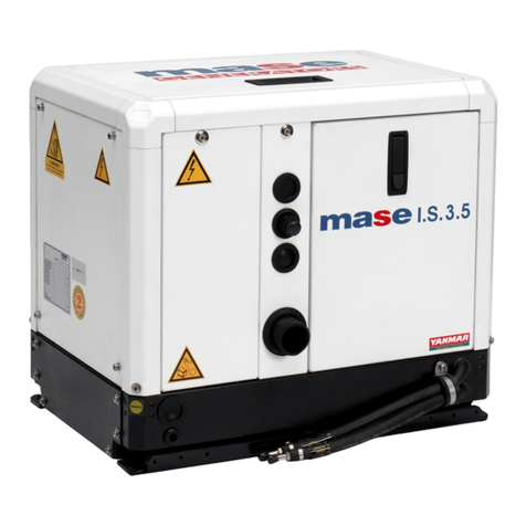
Mase Generators IS 6.1 User manual

Mase Generators

Mase Generators IS 6.1 User manual

Mase Generators MPL 66 A User manual

Mase Generators

Mase Generators MPL 66 A User manual

Mase Generators MARINER 1200 User manual

Mase Generators

Mase Generators MARINER 1200 User manual

Mase Generators IS 3.8 User manual

Mase Generators

Mase Generators IS 3.8 User manual

Mase Generators IS 3.5 User manual

Mase Generators

Mase Generators IS 3.5 User manual

Mase Generators MARINE I.S. 21.5 User manual

Mase Generators

Mase Generators MARINE I.S. 21.5 User manual

Mase Generators STAR 70 Series User manual

Mase Generators

Mase Generators STAR 70 Series User manual

Mase Generators VOYAGER User manual

Mase Generators

Mase Generators VOYAGER User manual

Mase Generators Marine IS 9.5 User manual

Mase Generators

Mase Generators Marine IS 9.5 User manual

Mase Generators EA 30 R User manual

Mase Generators

Mase Generators EA 30 R User manual

Mase Generators MW 171B User manual

Mase Generators

Mase Generators MW 171B User manual

Mase Generators MPF 33-44 User manual

Mase Generators

Mase Generators MPF 33-44 User manual

Mase Generators IS 7.6 User manual

Mase Generators

Mase Generators IS 7.6 User manual

Mase Generators Voyager 6020 Auto User manual

Mase Generators

Mase Generators Voyager 6020 Auto User manual

Mase Generators IS 3.5 User manual

Mase Generators

Mase Generators IS 3.5 User manual

Mase Generators MPL 143 S User manual

Mase Generators

Mase Generators MPL 143 S User manual

Mase Generators IS 10 T User manual

Mase Generators

Mase Generators IS 10 T User manual

Mase Generators IS 3.5 User manual

Mase Generators

Mase Generators IS 3.5 User manual

Mase Generators EA 50 R User manual

Mase Generators

Mase Generators EA 50 R User manual

Popular Portable Generator manuals by other brands

MULTIQUIP DCA125USI3CAN Operation and parts manual

MULTIQUIP

MULTIQUIP DCA125USI3CAN Operation and parts manual

Predator 57064 user manual

Predator

Predator 57064 user manual

RS PRO 123-6460 quick start

RS PRO

RS PRO 123-6460 quick start

Kübler CODIX 533 manual

Kübler

Kübler CODIX 533 manual

AdvanteX SG8-HP01M operating manual

AdvanteX

AdvanteX SG8-HP01M operating manual

Generac Power Systems GP3250 owner's manual

Generac Power Systems

Generac Power Systems GP3250 owner's manual

Briggs & Stratton 030663-00 Wiring diagram

Briggs & Stratton

Briggs & Stratton 030663-00 Wiring diagram

Aeroflex NAV-750C operating manual

Aeroflex

Aeroflex NAV-750C operating manual

Generac Power Systems XG Series owner's manual

Generac Power Systems

Generac Power Systems XG Series owner's manual

GW Instek ASR-2000 Series Programming manual

GW Instek

GW Instek ASR-2000 Series Programming manual

Tabor Electronics Lucid Series user manual

Tabor Electronics

Tabor Electronics Lucid Series user manual

SYSTEL PGX Technical manual

SYSTEL

SYSTEL PGX Technical manual

Tanaka QEG-250/300 parts catalog

Tanaka

Tanaka QEG-250/300 parts catalog

Doosan G60-SIIIA Operation & maintenance manual

Doosan

Doosan G60-SIIIA Operation & maintenance manual

Leroy-Somer LSA Series Installation and Maintenance

Leroy-Somer

Leroy-Somer LSA Series Installation and Maintenance

SIGLENT SSG3032X-IQE Service manual

SIGLENT

SIGLENT SSG3032X-IQE Service manual

Agilent Technologies HP 83711A user guide

Agilent Technologies

Agilent Technologies HP 83711A user guide

FRANCO G Series Instruction manual for use and maintenance

FRANCO

FRANCO G Series Instruction manual for use and maintenance

manuals.online logo
manuals.online logoBrands
  • About & Mission
  • Contact us
  • Privacy Policy
  • Terms and Conditions

Copyright 2025 Manuals.Online. All Rights Reserved.