less than 3 seconds, you can choose other range, when you press the
key for more than 3 seconds, it will turn back to auto range.
5.OPERATE INSTRUCTIONS
5-1.ACV/DCV measurement
Turn to range voltage, it will defaults to be ACV V~. Press
“SELECT”key can change to DCV.
a. Connect the red test lead to VΩterminal, and black test lead to
COM terminal.
b. Connect the test leads to the circuit which should be tested. Get the
result directly. When it is under the DCV, the polarity of the red test
lead will be shown together on the LCD.
5-2.Resistance Measurement
a. Turn to range , and press “SELECT” to choose the range
Ωmeasurement.
b. Connect the red test lead to VΩterminal, and black test lead to
COM terminal.
c. Connect the test leads to the circuit under tested or the both ends of
resistance
NOTE:
To measure resistance which is more than 2MΩ, the meter needs few
seconds to get the stable readings, and for the high resistance, this is a
normal situation.
When it is out of connection or under open circuit, it will shows “OL”.
When the online resistor is measured, be sure to shut off the line power
supply and discharge all capacitors completely.
5-3.Diode and Continuity test(buzzer function)
a. Connect the red test lead to VΩterminal, and black test lead to
COM terminal.
b. Turn to range , and press “SELECT” to choose the range
diode or continuity buzzer.
c. If the resistance between both ends of the circuit is less than about
30Ω, the built-in buzzer will sound.
d. Under the range DIODE, connect the red test probe onto the positive
of the diode and the black test probe onto the negative.
The forward conduction voltage drop will be shown on the LCD.
5-4.ACA measurement(A~)
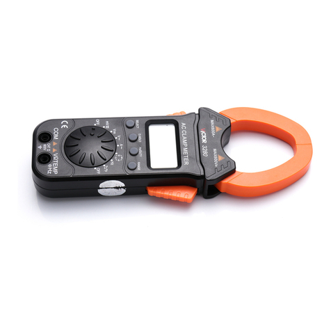
Turn to range 4/40A~or 600A~, place the wire vertically in the
center of the clamp head, and the reading is the ACA value.
5-5.Temperature measurement
a. Turn to range℃/℉.
b. Connect the K type thermocouple to the VΩterminal and COM
terminal of the meter, pay attention to the polarity during the
connection.
c. Place the test terminal on the surface of the tested object or inside it.
The temperature will show on the LCD.
NOTE:
1). Connect the temperature probe to the meter, the temperature value
will show on the LCD.
2). Without the signal input, LCD automatically displays the inside
temperature of the instrument.
5-6.Frequency Measurement(Hz)
a. Connect the red test lead to VΩterminal, and black test lead to
COM terminal.
b. Turn to range Hz, Connect the test leads to the circuit which should
be tested.
5-7.Capacitance Measurement
a. Connect the red test lead to VΩterminal, and black test lead to
COM terminal.
b. Turn to range , (note that the polarity of the red test lead is
positive.)
c. Connect the test leads to the both ends of capacitor. And check if the
polarity is correct.
NOTE :be sure to discharge all capacitors completely before
measurement, when testing the big capacitance, it needs about 10
seconds to get the stable value.
5-8.NCVmeasurement
Turn to range NCV, connect the clamp head to the wire or socket, when
the wire or socket got any AC signal through, the meter will judge the
signal and buzzer in different sound.
6.BATTERYREPLACEMENT
When symbol shows on the LCD, please replace the battery
(AAA 1.5V).
7.Note
In order to avoid the damage of the meter, please do not input 250V
DC or RMS AC under range /℃/℉/Hz/ .
8. Trouble shooting
If the meter does not work properly, check the meter as following:
601E-606B-000A
Fault Solution
No reading on LCD
●Power off--- Pls turn on the power
●Holding key---Pls set a correct mode
●Replace battery
The signal
appears
●Replace battery
Big error ●Replace battery
Back light is dark ●Replace battery
