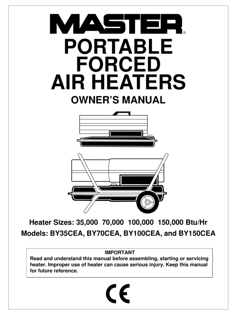
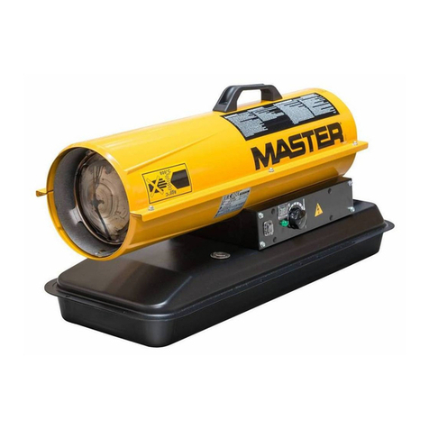
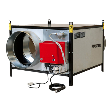
Master BF 35 User manual

GB – Hot air generator
Operation and maintenance manual
4111.805
Edition 10
Rev. 01
BF 35
BF 35BF 35
BF 35
BF 45
BF 45BF 45
BF 45
BF 75
BF 75BF 75
BF 75
BF 95
BF 95BF 95
BF 95
BF 105
BF 105BF 105
BF 105

CONTROL BOARD
1. Commutator
2. Room thermostat
3. Burner
4. Fuel tank
5. Limit thermostat
6. Fan
7. eat exchanger
8. Combustion chamber
9. Adjustable air head
5
3
2
1
4
6
7
8
9

ARNING: To avoid an overheating of the combustion chamber the fins must never be completely
closed. For this reason a blocking bar prevents the complete closure of the fins.
BF space heaters have been designed for use in medium to big sized rooms and buildings where a fixed heating
system is needed.
eat is produced by combustion and the heat from smoke is transmitted to fresh air through the metal walls of the
combustion chamber and the heat exchanger. The combustion chamber is of the type where smoke follows a
course of two modules.
Air and smoke pass through separated ducts, both of which are welded and sealed. When, after combustion, the
waste gases have cooled, they get expelled through a duct that has to be connected to a chimney or chimney flue
which must be big enough to guarantee that smoke gets efficiently expelled.
Air used for combustion gets aspirated directly from the room or building that is being heated. It is therefore very
important the room or building to be properly ventilated so that there is enough fresh air circulating at all times.
ot air can be sent in the desired direction by moving the fins on the air head.
BF heaters can operate with ON-OFF type and fuelled by heating oil burners. Where burners use oil, a front
attached fuel tank is provided (4). There are two safety devices which are activated in case of serious
malfunctioning. The burner control device, which is mounted on the burner and is provided with a restart button
that automatically stops the burner if the flame turns off, while the manual restarting type overheat thermostat
activates if the temperature of the combustion chamber reaches the set maximum limit.
If any of those safety devices are activated, you should check carefully what the problem is before pressing the
restart button and restarting the heater (check the “FUNCTIONING PROBLEMS: CAUSES AND SOLUTIONS”
paragraph).
GENERAL ADVICE
ARNING: Only chosen and by the manufacturer supplied burners can be used. If another type of
burner is used, the heater no longer complies with the CE regulations.
The space heater has to be installed, set up and used in accordance with existing laws. ere are a few general
guidelines which should be followed:
•Follow the instructions of this manual very carefully.
•Don’t install the heater in places where there might be risk of explosion or fire.
•Flammable material should be kept at a safe distance from the heater (3 meters minimum).
•All fire prevention measures have to be enforced.
•The room or building to heat has to be sufficiently ventilated so that the heather disposes of the needed ait
to work properly.
•The heater has to be near a chimney or a chimney flue and a suitable electric switchboard.
•Don’t let any children or animal get near the heater.
•After use, make sure that the disconnecting switch if off.
When using any type of space heater, it is compulsory to:
•Not exceed the maximum furnace heat output level.
•Make sure that a proper air circulation and supply is provided and that nothing might obstruct the air
aspiration and expulsion: that can be caused, for example, by placing covers or other objects on the
heater, or by positioning it too close to walls or other large objects. If there is an inadequate air supply,
the combustion chamber might start overheating, getting the overheat thermostat to intervene.
INSTALLATION
ARNING!
The following operations must be carried out by qualified personnel only.
ELECTRIC CONNECTIONS AND SETTINGS:
ARNING!
The main heater electricity supply has to be provided with grounding and a magneto-thermal switch
with a differential. The power wire has to be connected to a switch board linked to a disconnecting
switch.
The basic equipment of the heater includes all control and safety devices which can guarantee the correct
functioning of the machine: control board, room thermostat (2), fan and manual safety thermostat are already
connected.
The following operations have now to be carried out:
•Plug the power wire in after having read the adhesive label that shows electricity supply characteristics;
After having completed those operations, make carefully sure that all the electric connections match with the
wiring diagram. When the heater gets turned on for the first time, you should make sure that the fan does not
absorb more current than the maximum indicated limit. Eventually, to regulate the burner, follow the instructions
of the burner manual.
HOT AIR DUCTS CONNECTION
The space heater provides heat by releasing and diffusing hot air.
An air head which can be connected to air ducts, if the users chooses this option, is supplied with every machine.
In this case, and in particular if the diameter and length of the ducts get changed, or if the number of bends gets
modified, air output may vary. Consequently, it is very important to check and regulate air output when any
modification is made to air heads or ducts.
In all circumstances, you should make sure that:
•The fan engine does not absorb more current than the maximum indicated limit.
•The air flow volume matches with its recommended level.
CHIMNEY AND CHIMNEY FLUE CONNECTION
Efficient combustion and trouble-free working of the burner depend on an efficient smoke evacuation:
•The pipe which through which smoke passes should as short as possible and ascending.
•There should be no sharp bends and the diameter of the pipe should never be reduced.
•Every heater should have its own chimney.
•The chimney draught should at least enough and adequate for the needs of the equipment.
ASTE PRODUCTS ANALYSIS
The probes to check the combustion waste products composition and smoke temperature have to be positioned as
the picture below indicates.
When those tests have been completed, the hole drilled has to be sealed using a high temperature resistant
material which will ensure that the pipe remains airtight.

S ITCHING ON
To start the heater:
•Set the commutator (1) in the “O” position.
•Turn the disconnecting switch on the electric board on.
•Set the room thermostat (2) at the maximum level and set the commutator (1) in the position: the
burner will start and, after the combustion chamber has begun to heat, the fan will start too.
•If the heater does not start after you have completed the operations above, you should check the
“FUNCTIONING PROBLEMS: CAUSES AND SOLUTIONS” paragraph.
•If the heater is working normally:
1) Set the room thermostat at the desired level.
2) Move the adjustable fins of the air head (9) to reach the desired position.
TURNING OFF
ARNING!
You should never stop the heater by simply turning off the disconnecting switch on the electric
board. The electricity supply must only be disconnected when the fan has completely stopped.
Turn the commutator (1), in the “O” position. The burner will stop, while the fan might turn off and on a few times
until the combustion chamber has completely cooled down.
VENTILATION
When the commutator (1) gets turned to the position, the heater will work in continuous fan mode.
MAINTENANCE
ARNING!
The following operations have to carried out by qualified personnel only
For a correct work of the machine, it is necessary to perform the following operations periodically, remembering to
disconnect the power line before beginning.
Before carrying out any maintenance operation, you should:
•Stop the machine as indicated in the previous paragraph.
•Turn the disconnecting switch on the off position on the electric board.
•ait until the heater has completely cooled down.
HEAT EXCHANGER AND COMBUSTION CHAMBER CLEANSING
For the heater to operate efficiently, the heat exchanger and the combustion chamber have to be cleaned after a
period of prolonged use or even more frequently if you notice too much soot forms: that might happen with un
incorrect chimney draught, with a very bad quality fuel, with an incorrectly set burner or when the heater gets
turned on and off too often. If the heater starts vibrating when it is in the on position, there is probably too much
deposited soot.

To reach the internal part of the heat exchanger and the combustion chamber, remove the burner, the back lower
panel (C) as well as the exchanger inspection panel (E).
Using a vacuum cleaner or a ramroad, remove soot and extraneous material.
Models BF 35 – BF 45 – BF 75:
Models BF 95 – BF 105:
C E
F

FAN CLEANSING
Remove any extraneous material from the net of the aspiration grate (F) and, if necessary, clean the blades with
pressurized air blows.
BURNER CLEANSING
For the heater to function efficiently, the burner has to be regularly services by an authorized service technician.
All cleaning, servicing and regulation operations have to be performed as indicated in the burner manual.
TRANSPORTING AND MOVING THE HEATER
To move or transport the unit, place it on a raised base and then lift it with a forklift truck. There are no eyebolts
or other hooking points. The unit can also be placed on supports laying it down on the side that cannot be seen on
the first picture of the heater.
Before moving the machine, you should:
•Stop the machine as indicated in the previous paragraph.
•Turn the disconnecting switch on the off position on the electric board.
•ait until the heater has completely cooled down.
FUNCTIONING PROBLEMS: CAUSES AND SOLUTIONS
PROBLEM CAUSE SOLUTION
Heater won’t start 1. Faulty electric supply
2. Wrong main switch position
3. Wrong room thermostat setting
4. Safety device (burner, safety
thermostat) non restarted after
repair
1. Check functioning and positioning of
main switch
1. Check power wire
1. Check electric connections
1. Check fuses
2. Set main switch in the correct
position
3. Check room thermostat setting and
functioning
4. Press restarting button
Limit Thermostat intervention 1. Combustion chamber has overheated 1. Check fuel flow
1. Check registers, draw-holes, etc.
position
1. Remove extraneous material from air
ducts and ventilation grates
Burner starts working but the
flame does not light up and reset
light turns on
1. Irregular burner functioning 1. Press restarting button to turn on the
heater. If the same problem arises
again call an authorizes service
technician
Fan does not start or does it late 1. Faulty electric supply
2. Out of order fan
3. Burnt or interrupted engine winding
4. Burnt engine condenser
5. Blocked engine bearings
1. Check fuses
1. Check electric connections
2. Check the thermostat, set it and
replace it if necessary
3. Replace fan engine
4. Replace condenser
5. Replace bearings
Vibrating or producing unusual
noise fan
1. Extraneous material on fan blades
2. Low air circulation
1. Remove extraneous materiel
2. Remove obstacles to air circulation
Insufficient heating 1. Burner insufficient capability 1. Call an authorized Service Technician

TECHNICAL DATA
MODEL BF 35 BF 45 BF 75 BF 95 BF 105
Single phase power supply 230V
∼
50 z
Air flow 1.900 m³/h 2.800 m³/h 4.500 m³/h 5.300 m³/h 6.300 m³/h
Cosumption 2,84 kg/h 3,95 kg/h 6,0 kg/h 7,84 kg/h 8,82 kg/h
Fuel Oil
Maximal thermal power 33,7 kW 46,8 kW 71,1 kW 93,0 kW 104,6 kW
Fan electric power 245 W 245 W 590 W 736 kW 736 kW
Flue diameter 120 mm 120 mm 150 mm 180 mm 200 mm
Fan starting temperature +35 °C
Safety limit temperature +100 °C
Fuel tank 55 litres 55 litres 75 litres 105 litres 135 litres
Dimensions L x P x 460x1050x1600
mm
460x1050x1600
mm
540x1120x1700
mm
680x1220x1885
mm
760x1400x2000
mm
Net weight (without burner) 132 kg 137 kg 173 kg 197 kg 264 kg
Riello Burner REG 3 REG 5 R40 G10S R40 G10S R40 G10S
ELECTRIC DIAGRAM
LF Tension signal
LL LIMIT intervention signal
LB Burner block signal
C eating / stop / fan commutator
TA Room thermostat
LM LIMIT thermostat
FA FAN thermostat
MB Burner terminal board
B Burner
MGV Fan group terminal board
GV Fan group
P External plug
IMT* Magneto-thermal interruptor qitt
* Outside the machine, under installer’s
responsibility.

DECLARATION OF CONFORMITY CE:
The company:
DESA Italia s.p.a. - Via Tione, 12 - 37010 Pastrengo (Vr) - ITALY
Declares under its responsibility that the machine:
Hot air generator:
BF 35 – BF 45 – BF 75 – BF 95 – BF 105
Complies with:
98/37 CE, 91/368, 93/44, EMC 89/336, 92/31, 93/68, 73/23.
Pastrengo, september 2010 Raffaele Legnani
(Managing Director)
PRODUCT DISPOSAL
Your product is designed and manufactured with high quality materials and components which can be recycled and
reused.
When you find this crossed-out wheeled symbol on a product, that means that it is covered by the European
Directive 2002/96/EC.
Please inquire about the local collection of items for recycling system for electric and electronic products.
Please act according to your local rules and do non dispose the product with the normal domestic waste: the
correct disposal of this product will help preventing potential negative consequences for both environment and
human health.


DESA ITALIA s.p.a.
Via Tione, 12 – 37010
Pastrengo (Verona) – Italy
www.desaitalia.com
info@desaitalia.com
DESA POLAND Sp. Z.o.o
ul Magazynova 5A, 62-023
Gadki, Poland
www.desapoland.pl
office@desapoland.pl
DESA HEATING EQUIPMENT
SHANGHAI CO., LTD
Rm. 2203, 218, HengFeng Rd,
Shanghai, China, 200070
www.desa-china.com
info@desa-china.com
This manual suits for next models
4
Table of contents
Other Master Heater manuals

Master
Master MH-150T-DFV Manual

Master
Master BV 310FS Manual

Master
Master BLP 100 E User manual

Master
Master MH-80TBOA-OFR Training manual

Master
Master MH-375T-GFA-A Training manual

Master
Master BV 110 E User manual

Master
Master XL6 Manual

Master
Master B 1,8 ECA User manual

Master
Master B 18 EPR User manual

Master
Master TB116 User manual

Master
Master BV Series Manual

Master
Master WA33C Manual

Master
Master BC350D User manual

Master
Master WA 41 A User manual

Master
Master BV 471S Manual

Master
Master MH-600T-KFA Training manual

Master
Master AIR-BUS BV 471S Manual

Master
Master CHAP 18 Manual

Master
Master MH-221A-120 Training manual

Master
Master XL 9ER Manual