MasterPower Delta UM Series User manual

If you encounter any problem on the inverter, please find out the inverter S/N
and contact us, we will try to respond to your question ASAP.
Delta UM Series Off-grid Inverter
Instruction Manual
Ver 1.0
Please adhere to the actual products in case of any discrepancies in this user manual.
Master Battery, S.L.
Paseo de Extremadura, 39, 28935 Móstoles
Madrid, Spain
Tel: +34 918 021 649
Fax: +34 917 750 542
Email: [email protected]
Web: www.masterbattery.es

2
4
7
7
8
11
13
14
4
2
3
9
18
26
28
21
20
20
1.1 Product Description
………………………………………………………………………………………………………………………………
…………………………………………………………………………………………………………
……………………………………………………………………………………………………………………………………
……………………………………………………………………………………………………………………………
……………………………………………………………………………………
……………………………………………………………………………………………
…………………………………………………………………………………………………………
…………………………………………………………………………………………………………………
…………………………………………………………………………………………………………………………
1. Introduction
1.2 Packaging
2. Safety & Warning
2.1 Safety
2.2 General Safety Instructions
3. Installation
3.1 Select a Location for the Inverter
3.2 Mounting the Inverter
3.3 Preparation
3.5 Assembling the AC Connector
3.6 Grounding
4. Operation
4.1 Startup guide
4.3 Information
4.4 Settings
4.5 Advanced Infomation
Contents
………………………………………………………………………………………………………
………………………………………………………………………………………………………………………………
4
42
42
42
…………………………………………………………………………………………
………………………………………………………………………………
…………………………………………………………………………………………………………………
5. Commissioning
5.1 Preparation of Commissioning
5.2 Commissioning Procedure
7. Troubleshooting ……………………………………………………………………………………………………………… 44
32
………………………………………………………………………………………………………………
4.6 Advanced Settings
…………………………………………………………………………………………………………………………………
……………………………………………………………………………………………………………………………
………………………………………………………………………………………………………………………………
……………………………………………………………………………………………………………………………………
2.3 Notice For Use 6
…………………………………………………………………………………………………………………………
………………………………………………………………………………………
………………………………………………………………………………………
16
50
…………………………………………
………………………………………………………………………………………………………………………
8. Specifications
……………………………………………………………………………………………………………
9. Appendix 54
…………………………………………………………………………………………………………………………………
…………………………………………………………………………………………………………
10
3.4 PV Input Terminal Assembly …………………………………………………………………………………………
20
4.2 Main Menu ………………………………………………………………………………………………………………………………
6. Maintenance ……………………………………………………………………………………………………………………… 43
6
……………………………………………………………………………………………………………………
2.4 Notice for Disposal
3.7 Battery Terminal Components
3.8 Battery communication and external communication
3.9 Parallel Connection
3.10 LED Indicates
3.11 Power-on instructions
19
19
……………………………………………………………………………………………………………………
……………………………………………………………………………………………………

1.1 Product Description
Inverter x1 R terminal x3 Sheet copper terminal x12 Fixing screws x1
.3..2.
1. Introduction 1. Introduction
1.2 Packaging
Please ensure that the following items are included in the packaging with your machine:
Expansion bolt x3 Temperature Sensor x1 User manual x1
If anything is missing, please contact your local MasterPower distributor.
Delta UM series inverter is designed for residential off-grid systems in the countries without
stable grid power, which can work with batteries to supply power to load and can also charge
the batteries through PV plants, grid or generator.
This manual covers the Delta UM inverter model listed below:
Delta UM 4K-48, Delta UM 4K-48 Top, Delta UM 5K-48, Delta UM 5K-48 Top
Manual
Figure 1.1
Product Description
1
2 3 4
5
6 7 8 9
10 11 12 13 14 15 16
Table 1.1
Product Description
NO. Description NO. Description
1
2
3
4
5
6
7
8
9
10
11
12
13
14
15
16
LCD display
Status indicator
Charging indicator
Fault indicator
Function buttons
COM port
PV input
AC output
AC input
Parallel communication ports
Dry contact
RS-485 Communicaton Port
Battery Communication Port
Battery Connection
Circuit Breaker
Battery awaken switch
NOTE:
Please refer to the specification of the battery before configuration.

2.1 Safety
The following types of safety instructions and general information appear in this document as
described below:
.5..4.
CAUTION:
“Caution” indicates a hazardous situation which if not avoided, could result
in minor or moderate injury.
WARNING:
“Warning” indicates a hazardous situation which if not avoided, could result
in death or serious injury.
DANGER:
“Danger” indicates a hazardous situation which if not avoided, will result in
death or serious injury.
NOTE:
“Note” provides tips that are valuable for the optimal operation of your
product.
2. Safety & Warning 2. Safety & Warning
2.2 General Safety Instructions
WARNING:
Electrical installations must be done in accordance with the local and national
electrical safety standards.
WARNING:
Please don’t connect PV array positive (+) or negative (-) to ground, it could
cause serious damage to the inverter.
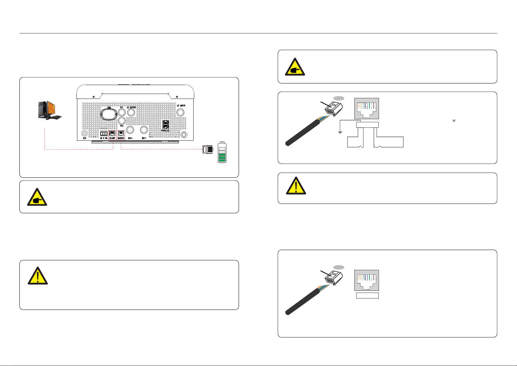
WARNING:
Only devices in compliance with SELV (EN 69050) may be connected to the
RS485 and USB interfaces.
WARNING:
Do not touch any inner live parts until 5 minutes after disconnection
from the utility grid and the PV input.
CAUTION:
The PV array supplies a DC voltage when they are exposed to sunlight.
CAUTION:
Risk of electric shock from energy stored in capacitors of the Inverter, do not
remove cover for 5 minutes after disconnecting all power sources (service technician
only). Warranty may be voided if the cover is removed without authorization .
CAUTION:
The surface temperature of the inverter can reach up to .60℃ (140 ℉)
To avoid risk of burns, do not touch the surface of the inverter while it’s operating.
Inverter must be installed out of the reach of children.
WARNING:
To reduce the risk of fire, over-current protective devices (OCPD) are
required for circuits connected to the inverter.
The DC OCPD shall be installed per local requirements. All photovoltaic source
and output circuit conductors shall have that comply with the NECisolators
Article 690, Part II.
CAUTION:
Risk of electric shock, do not remove cover. There is no user serviceable
parts inside, refer servicing to qualified and accredited service technicians.
NOTE:
PV module used with inverter must have an IEC 61730 Class A rating.
WARNING:
Operations below must be accomplished by licensed technician or MasterPower
authorized person.
WARNING:
Operator must put on the technicians’ gloves during the whole process in case
of any electrical hazards.
WARNING:
For PV system, between the PV string and PV input of the inverter, it is
required to install a DC isolator to meet local installation regulations.

2. Safety & Warning
2.3 Notice For Use
The inverter has been constructed according to the applicable safety and technical
guidelines. Use the inverter in installations that meet the following specifications ONLY:
1. Permanent installation is required.
2. The electrical installation must meet all the applicable regulations and standards.
3. The inverter must be installed according to the instructions stated in this manual.
4. The inverter must be installed according to the correct technical specifications.
.6. .7.
2.4 Notice for Disposal
This product shall not be disposed of with household waste. They should
be segregated and brought to an appropriate collection point to enable
recycling and avoid potential impacts on the environment and human health.
Local rules in waste management shall be respected .
3. Installation
3.1 Select a Location for the Inverter
To select a location for the inverter, the following criteria should be considered:
Exposure to direct sunlight may cause the output power to decrease. It is
recommended to install the inverter indoors,avoid direct sunlight and rain.
It is recommended that the inverter is installed in a cooler ambient which doesn't
exceed 131℉/55℃.
To avoid overheating, always make sure the flow of air around the inverter is not
blocked. A minimum clearance of 200mm should be kept between inverters or
objects and 500mm clearance between the bottom of the machine and the ground.
Install vertically with a maximum incline of +/- 5 degrees, exceeding this may cause
output power derating.
Figure 3.1 Inverter Mounting clearance
Install on a wall or strong structure capable of bearing the weight of the machine (13.3kg).
WARNING: Risk of fire
Despite careful construction, electrical devices can cause fires.
Do not install the inverter in areas containing highly flammable materials
or gases.
Do not install the inverter in potentially explosive atmospheres.
50cm
Visibility of the LEDs and LCD should be considered.
Adequate ventilation must be provided.
NOTE:
Nothing should be stored on or placed against the inverter.
50cm
20cm20cm
WARNING:
Thus according to IEC60634-7-712 (VDE100-712) ,if the PV inverter isn’t able
toinject direct current to ground (i.e isn’t able to leak direct current),
it is not required toinstall a B-type RCD at the output of a MasterPower inverter.
MasterPower require using amagneto-thermic automatic switch with an RCD
module (with adequate voltage andcurrent rating basing on the grid characteristics
and on the output current of theinverter) with a sensitivity of 30mA, A-type. This
switch with the RCD module need to be installed on the AC input side.

.9..8.
3. Installation3. Installation
3.2 Mounting the Inverter
Figure 3.2 Wall Mount inverter
WARNING:
The inverter must be mounted vertically.
Select the mounting height of the inverter and mark the mounting holes. It’s
recommended to install the inverter tighten by using two M5 screws.
Figure 3.3 Fix inverter on the wall
3.3 Preparation
Before connecting all wiring, please take off bottom cover by removing screws as
shown below.
Figure 3.4 Remove the junction box cover
Fix the two holes on the top of the machine and one hole in the box with screws.

3.4 PV Input Terminal Assembly
Please ensure the following before connecting the inverter:
Make sure the voltage of the PV string will not exceed the max DC input voltage (550Vdc).
Violating this condition will void the warranty.
Make sure the polarity of the PV connectors are correct.
Make sure the battery, AC Input, and AC Output are all in their off-states.
Make sure the PV resistance to ground is higher than 20K ohms.
PV wire diameter requirements:12AWG.
Figure 3.5
1. Remove insulation sleeve 10 mm for positive and negative conductors.
3. Please ensure the secure and correct polarity connection between PV modules and PV
input connectors, or the system will be damaged. Connecting positive pole (+) of connection
cable to positive pole (+) of PV input connector. Connecting negative pole (-) of connection
cable to negative pole (-) of PV input connector.
PV1 PV2
Figure 3.6 PV Input terminals
.10. .11.
3.5 Assembling the AC Connector
To protected from over current of AC input, MasterPower recommends installing a separate
AC breaker between inverter and AC input power source. (At least 32A)
ITEM CABLESIZE TORQUE
PE
L
N
12AWG
10AWG
10AWG
1.0-1.2Nm
1.2-1.6Nm
1.2-1.6Nm
L
N
12AWG
12AWG
1.0-1.2Nm
1.0-1.2Nm
AC Input
AC Output
1. Ensure the cables within the suitable specifications as shown in the table below.
4.Insert AC input wires according to polarities indicated on terminal block and tighten the
terminal screws. Make sure that the PE protective conductor is connected firstly, and the
connection sequence should be PE/L/N.
Figure 3.7 AC Input terminals
Table 3.1 AC wire specification
Before connecting to PV modules, please install separately a DC circuit breaker
between inverter and PV modules.
PE/L/N
2. Insert the wire into the sleeve and use a suitable crimping tool for crimping.
10mm Crimping plier
Crimping sleeve
(In the accessory bag)
2. Remove insulation sleeve 10 mm for positive and negative conductors.
3. Insert the wire into the sleeve and use a suitable crimping tool for crimping.
(see Figure 4.6)
PE/L/N
3. Installation3. Installation

.13..12.
6.Insert AC output wires according to polarities indicated on terminal block and tighten
terminal screws with the torque of 1.0-1.2Nm. The connection sequence should be L-N.
7.Make sure the wires are securely connected.
WARNING:
Be sure to connect AC wires with correct polarity. If L and N wires are
connected reversely, it may cause utility short-circuited when these
inverter are working in the parallel operation.
Figure 3.9 AC Output terminals
5.The Dry Contact is used to be one AC source of Generator.
Description Signal Name Pin
NC RELAY1_NC 1
COM RELAY1_COM 2
NO RELAY1_NO 3
Figure 3.8 Dry Contact
PE/L/N
3.6 Grounding
To effectively protect the inverter, a grounding methods must be performed.
Connect the external grounding terminal.
To connect the grounding terminal on the heat sink, please follow the steps below:
3. Connect the grounding cable to the grounding point on the heat sink, and tighten the
grounding screw, Torque is 3Nm.
1. Remove insulation sleeve 10 mm for positive and negative conductors.
2. Insert the wire into the sleeve and use a suitable crimping tool for crimping.
Figure 3.10
10mm Crimping plier
Crimping sleeve
(In the accessory bag)
Grounding screw
For improving anti-corrosion performance, after ground cable installed,
apply silicone or paint is preferred to protect.
Important:
Figure 3.11 Grouding
3. Installation3. Installation
NOTE:
MasterPower recommends to install a 230V/40A single-phase dual-channel
normally open AC contactor on the external of the grid input , when grid
is avaliable, the contractor will stay 'on' , when the grid is off, the contractor
will automatically disconnect itself from the grid.
Recomended Type: Chint NCH8 series 40A2P

3.7 Battery Terminal Components
If you choose lead-acid battery, you are allowed to use AGW-type, flooded-type and
Gel-type. It is necessary to consider that the battery voltage to connect with the inverter
is 48V.
Considering the installation environment and operation safety, please pay attention to
the following points:
The natural surrounding ventilation of Lead-acid battery should be well and the
environment temperature is better around 25±10℃.
Fix the bolts of wire terminal to prevent the battery from sparking and poor connection.
The battery should avoid direct sunlight, DON’T put the batteries in the environment
with lots of radiation, infrared radiation, ultraviolet radiation, organic solvent gas
and corrosive gas.
The different batteries with different capacity and functionality can’t be interconnected
with each other, check the total voltage, polarity of positive and negative port before the
installation of end connection device and turning on the battery system.
Ensure the installation site has enough carrying capacity to support the battery system.
3.7.1 Lead-acid Battery
If you choose a lithium battery, you are allowed to use Pylontech, BYD and Dyness.
3.7.2 Lithium Battery
Considering the installation and operation safety, please pay attention to
the following points:
Before compeleting the final DC connection or closing DC breaker, please ensure the
correct polarity of battery connection and positive (+) must be connected to BAT (+)
and negative (-) must be connected to BAT (-).
Please carefully read the user manual of the battery and strictly follow the precautions
in the battery manual.
3. Installation3. Installation
Insert the ring terminal of battery cable flatly into battery connector of inverter and make
sure the bolts are tightened with torque of 1.2-1.6Nm.
Make sure polarity at both the battery and the inverter is correctly connected and ring
terminals are tightly screwed to the battery terminals.
Note:
Before connecting the battery, please carefully read the user manual of the
battery and perform the installation exactly as the battery manufacturer
requests.
ITEM COLOUR CABLESIZE TORQUE
BAT+
BAT-
RED
BLACK
6AWG
6AWG
1.2-1.6Nm
1.2-1.6Nm
Battery
To avoid DC Arc, MasterPower recommends installing DC switch between batteries and
Inverter. Ensure the cables within the suitable specifications as shown in the table below.
3.7.3 Battery Connection
Figure 3.12 Connected to the battery fuse terminals
Table 3.2 Battery power cable requirement
Bat + Bat -
.15..14.

3.8 Battery communication and external communication
The Delta UM series inverter uses RS485 cable to communicate with BMS/NTC port to
communicate with the BMS of Lithium and NTC of Lead-acid battery. The image below shows
the assembly of the communication cables. RS-485 is one standard communication interface
which can transmit the real data from inverter to PC or other monitoring equipments.
Figure 3.13
Procedure for connecting the BMS cable:
1. Take out the CAN cable (terminal marks ‘CAN' on one end and 'to Battery' on the other end).
2. Unscrew the swivel nut from BMS/NTC port.
3. Insert the RJ45 terminal with CAN label into the BMS/NTC port, then fasten the swivel nut.
4. Connect the other end to the battery.
NOTE:
Lead-Acid and other older-technology battery types require experienced
and precise design, installation and maintenance to work effectively.
For lead-acid battery , battery SOC calculation may not be accurate
according to battery inconformity between cells, battery aging or other
specifications of lead-acid battery etc.
CAN
Monitoring equipments
NOTE:
NTC temperature sensor should be attached to the surface of lead-acid
battery for detecting the temperature in the real time.
3. Installation3. Installation
NOTE:
For CAN/485 cable pin 4 (blue) and pin 5 (white-blue) are used for the
communication.
Procedure for connecting the RS485 cable:
1. Take out the RS485 cable.
2. Unscrew the swivel nut from RS485 port.
3. Insert the RJ45 terminal with RS485 label into the RS485 port, then fasten the swivel nut.
4. Connect the other end to PC or other monitoring equipments.
Correspondence between the
cables and the stitches of plug
are as below:
Pin 1: RT1; Pin 2:
Pin 3: RT2; Pin 4: CAN_H
Pin 5: CAN_L; Pin 6:NC
Pin 7: BMS485_A; Pin 8: BMS485_B
1--8
RJ45 plug RJ45terminal
12345678
12345678
BMS(CAN/485)
Figure 3.15 RS485 serial communication pin definition
Note:
Before connecting the battery, please carefully read the user manual of the
battery and perform the installation exactly as the battery manufacturer
requests.
GND
Correspondence between the
cables and the stitches of plug
are as below:
Pin 1: GND; Pin 2: WIFI_B
Pin 3: WIFI_A; Pin 4: RS485_A
Pin 5: RS485_B; Pin 6: NC
Pin 7: +5V_RS485; Pin 8: +5V_WIFI
Figure 3.14 Strip the insulation layer and connect to RJ45 plug
1--8
RJ45 plug
RJ45terminal
12345678
12345678
NTC
.17..16.

3.9 Parallel Connection
The "-P" type in the Delta UM series inverter has the parallel capability and can be operated
in parallel.
This inverter can be used in parallel with two different operation modes.
1.Parallel operation in single phase with up to 10 units.
2.Maximum 10 units work together to support 3-phase equipment.
n
PV PV
LOAD
GRID
GENERATOR
BATERY
n≤10pcs
Figure 3.16 Parallel operation in single phase
DC AC Communication
GRID
BATTERY BATTERY BATTERY
PV
n2 n3
ATS
GENERATOR
PV PV PV PV PV single phase LOAD
three phase LOAD
DC AC Communication
Figure 3.17 Parallel operation in three phase
n1+n2+n3≤10pcs
n1≥1
n2≥1
n3≥1
threephaseLOAD
must be Y type
n1
Please refer to《parallel quick installation guide》.
3. Installation3. Installation
Description
Status
Light
BATTERY
3.10 LED Indicates
There are three LED indicators on the Delta UM series inverter which indicate the working status.
Table 3.3 Status Indicator Lights
Color
FLASHING
ON
OFF
Green
The inverter is in self-test(Fast flashing for 3S).
The inverter is in standby(Slow flashing for 3S).
The inverter is normally operational.
No power to the inverter system.
Green/Yellow
Yellow/Red
ALARM
STATUS
GREEN FLASHING
GREEN CONSTANT
Battery is charging.
Battery is discharging.
YELLOW CONSTANT
OFF Battery is not working.
Battery failure.
YELLOW CONSTANT
RED CONSTANT
OFF
There is an alarm but system working normally.
There is an alarm but system stops.
No Alarm.
3.11 Power-on instructions
1. The LCD screen can light up with only PV, battery or grid connected to it.
2 .If it is required to support the loads with backup power ,battery must be installed.
After the backup port starts to output, turn off the battery, and the loads can continue
to be supported by the grid power.
3. MasterPower suggestion on powering on the inverter: Firstly turn on the battery, then turn on PV
and grid in turns.
.18. .19.

4. Operation
Figure 4.1 Operation Overview
4.2 Main Menu
There are four submenu in the Main Menu (see Figure 4.1):
1. Information
2. Settings
3. Advanced Info.
4. Advanced Settings
Start Main interface
Information
Settings
AdvancedInfo.
Advanced Settings
UP/DOWN
UP/DOWN
UP/DOWN
Pressing the ENTER
key to switch
to the submenu
Pressing the ESC
key calls back
the previous menu
ENTER
3 sec
4.1 Startup guide
Please follow the steps to complete the initial setup process. steps are as followed:
Start up Wizard Language > Time >Connect battery? >Battery Type >
Connect generator? >Back up setting> Setting successfully
4. Operation
4.3 Information
In the information section, operating data and information data can be viewed.
Sub-sections include:
1. General Information
2. System Information
3. Energy Records
4. BMS information
4.3.1 General Information
The example displays are shown in the following figures.
The user can view it by pressing the up and down keys.
Values are for reference only.
Figure 4.2 General Information
Inverter SN:
000000000000000
SoftVer.:
040000
Display Description
Mute State:
OFF
Model. :
S5-E01P5K-48
Shows the inverter serial number.
Show the mute status of the device.
Shows the model of the device.
Shows the DSP and ARM version of the inverter.
.20. .21.

V_DC:
I_DC:
000.0V
000.0A
4.3.2 System Information
Figure 4.3 System Information
Display Description
The example displays are shown in the following figures.
The user can view it by pressing the up and down keys.
Values are for reference only.
V_AC:
I_AC:
000.0V
000.0A
Shows the grid frequency value.
Grid Frequency:
00.00Hz
Battery V:
Battery I:
Backup V:
Backup P:
Charge P:
DisCharge P:
000.0V
000.0A
000.0V
00.0kW
00.0kW
00.0kW
Shows the voltage on DC side.
Shows the current on DC side.
Shows the voltage on AC side.
Shows the current on AC side.
Shows the battery voltage.
Shows the battery current.
Shows the voltage on backup.
Shows the power on backup.
Shows the charging power.
Shows the discharging power.
4.3.3 Energy Records
Sub-sections of the Yield information section include:
1. Battery Yield
2. Grid Yield
3. Load Yield
The example displays are shown in the following figures.
Values are for reference only.
Figure 4.4 Battery Yield
BattChgE Today:
000.0kWh
Shows the total battery charged energy.
Shows yesterdays’ battery charged energy.
Shows the total battery discharged energy.
Shows todays’ battery discharged energy.
Shows yesterdays’ battery discharged energy.
Shows todays’ battery charged energy.
Display Description
BattChgE Total:
0000000kWh
BattChgE Lastday:
000.0kWh
BattDisChgE Total:
0000000kWh
BattDisChgE Today:
0000000kWh
BattDisChgE Lastday:
0000000kWh
GridGetE Lastday:
000.0kWh
Shows the total energy received from the grid.
GridGetE Total:
0000000kWh
GridGetE Today:
000.0kWh
Shows yesterdays’ energy received from the
grid.
Shows todays’ energy received from the grid.
Figure 4.5 Grid Yield
Display Description
4. Operation4. Operation
.22. .23.

Figure 4.6 PV Yield
Display Description
PV E Total:
000.0kWh Shows total energy received from PV side.
Shows todays' energy receive from PV side.
Shows yesterday's energy received from PV side.
Figure 4.7 Load Yield
Display Description
LoadE Total:
0000000kWh
LoadE Today:
000.0kWh
LoadE Lastday:
000.0kWh
Shows total load energy.
Shows todays’ load energy.
Shows yesterdays’ load energy.
PV E Today:
000.0kWh
PV E Lastday:
000.0kWh
4.3.4 BMS Information
The example displays are shown in the following figures.
The user can view it by pressing the up and down keys.
Values are for reference only.
Figure 4.8 BMS Information
BMS Status:
CAN Fail
BMS Version:
0.0
Display Description
Battery V:
Battery I:
00.00V
+00.00A
ChargeILmt:
DischargILmt:
ChargeVLmt:
DischargVLmt:
000.0A
000.0A
000.0A
000.0A
SOC Value:
SOH Value:
000%
000%
Battery V: Shows battery voltage(From BMS).
Battery I: Shows battery current(From BMS).
Shows that Battery BMS communication status.
Shows that Battery BMS version.
SOC value: Shows battery state of charge.
SOH value: Shows battery state of health..
ChargeILmt: Shows battery charge limit(Current).
DischargeILmt: Shows battery discharge limit(Current).
ChargeILmt: Shows battery charge limit(Voltage).
DischargeILmt: Shows battery discharge limit(Voltage).
BMS ONLY support CAN communication not RS485, and all the data will display “0"
when the battery has been selected as Lead-acid battery which is monitored by NTC
in CAN/NTC port.
4. Operation4. Operation
.25..24.

The following submenus are displayed when the Settings menu is selected:
1. Set Time/Date
2. Set Address
3. Set Mute
4. Mode Settings
4.4 Settings
4.4.1 Set Time/Date
This function allows time and date setting. When this function is selected, the LCD will
display a screen as shown in Figure 4.9.
NEXT=<ENT> OK=<ESC>
01-01-2020 00:00
Figure 4.9 Set Time
4.4.2 Set Address
This function is used to set 1. Modbus address 2. Inverter parallel address 3 to connect
other devices like data logger etc.
YES=<ENT> NO=<ESC>
Set Address: 02
Figure 4.10 Set Address
4.4.3 SetMute
This function allows you to turn on/ off the keypad tone and buzzer sound.
Choose' ON' to disable the sounds and choose 'OFF' to enable the sounds. Default is 'OFF'.
Set Mute:
OFF
Figure 4.11 Set Mute
4.4.4 Mode Settings
Figure 4.12 Mode Settings
Work Mode
Charger Src. Pri.
Mode Settings explain different kinds of work modes.
4.4.4.1 Work Mode
This unit allows Output source priority setting, The specific setting are shown in the
following figures.
Work Mode:
Batt Reserve
Work Mode:
Back up
Work Mode:
Self Use
PV will give priority to the load, and the excess energy will
charge the battery.
When the PV energy supply is insufficient for the load, battery
energy will supply loads at the same time.
Grid will supply the loads when battery reached the low-level
voltage or the setting point or PV is not available.
Grid will provide power to the loads as first priority.
PV and battery will provide power to the loads only when
Grid is not available.
PV provide power to the loads as first priority.
If PV is not sufficient to power all connected loads, battery
will supply power to the loads at the same time.
If battery reached the low-level voltage or the setting point,
PV will provide power to the battery and Grid will supply load .
Figure 4.13 Work Mode
Display Description
4.4.4.2 Charger Source Priority
If this off grid inverter is working in Line, Off or Fault mode, this unit will allow
charger source priority setting, The specific setting are shown in the following figures.
PV will be the only charger source no matter grid is available
or not.
PV and Grid will charge battery at the same time.
Charger Src. Pri.
PV Only
Charger Src. Pri.
PV&Grid
Display Description
Figure 4.14 Charger Source Priority
4. Operation4. Operation
.26. .27.

4.5 Advanced Information
NOTE:
To access to this area is for fully qualified and accredited technicians only.
Enter menu “Advanced Info.”(Initial password “1000").
After enter the correct password 1000 access to the following information
1. Alarm Message
2. Warning Message
3. Running Status
4. Communication data
5. Yield Profile
YES=<ENT> NO=<ESC>
Password:0000
Figure 4.15 Enter password
The screen can be scrolled by pressing the UP/DOWN keys.
Pressing the ENTER key gives access to a submenu.
Press the ESC key to return to the Main Menu.
4.5.1 Alarm Message
The display shows the 20 latest alarm messages.
Screens can be scrolled by pressing the UP/ DOWN keys.
Alm000: NO-Grid
T:01-01 00:02 D:0000
Figure 4.16 Alarm Message
Press the ESC key to return to the previous menu.
Press the ENTER key to return to the next menu.
The example displays are shown in the following figures.
Values are for reference only.
The display shows the latest warning message.
Press the ESC key to return to the previous menu.
Msg000:
T:01-01 00:02 D:0000
Figure 4.17 Warning Message
4.5.2 Warning Message
4.5.3 Running Status
This function is for maintenance person to get running message such as Heat sink
temperature, Standard NO. etc.(Values are for reference only).
Figure 4.18 Running Status
General Status
Advanced Status
Figure 4.19 General Status
DC Bus Voltage:
0.0V
Display Description
Power Factor:
+0.000
Power Limit%:
000%
Inverter Temp:
+0.0degC
Grid Standard:
Flash State:
11111111
Shows DC bus voltage.
Shows power factor of the inverter.
Showsthepoweroutputpercentageoftheinverter.
Shows current effective grid standard.
Shows the data migration time.
NOTE:
The advanced status is reserved for MasterPower technicians.
Shows heat sink temperature of the inverter.
4. Operation4. Operation
.29..28.

Figure 4.20 Advanced Status
Ground Voltage:
000.0V
Display Description
Relay-Fault Func.:
RUN
GRID-INTF.02 Func.:
RUN
4.5.4 Communication data
This section shows the communication Data between HMI and DSP. For
MasterPower Software engineer ONLY.
Figure 4.21 Communication data
01-05: 00 00 00 00 00
06-10: 00 00 00 00 00
Shows the status of the replay.
Shows the voltage to the ground.
Shows the interference status from the grid.
4.5.5 Yield Profile
4.5.5.1 Energy Battery
Shows the battery charged &discharged energy.
Battery Discharge
Shows the energy battery charged.
Shows the energy battery discharged.
Battery Charge
4.5.5.2 Energy Grid
Energy get from the grid.
4.5.5.3 Energy Backup
Energy generated from backup port.
Figure 4.22 Battery Charge
Display Description
Shows the energy received from the grid.
Get Energy
Figure 4.23 Get Energy
Display Description
Monthly Energy
Shows the .daily energy
Shows the .yearly energy
Shows the .monthly energy
Daily Energy
Yearly Energy
Figure 4.24 Energy Backup
Display Description
4. Operation4. Operation
.30. .31.

4.6 Advanced Settings
NOTE:
To access to this area is for fully qualified and accredited technicians only.
Enter menu “Advanced settings” (Initial password"1000").
YES=<ENT> NO=<ESC>
Password:0000
Figure 4.25 Enter password
4.6.1 Output Settings
This function is to control the output power on the load port.
On Backup ON/OFF , when choose ON, power can be allowed to export.
When choose OFF, power can't be allowed to export, default is ON.
Figure 4.26 Set Backup
After enter the correct password 1000 access to the following information
1. Output Settings
2. Battery Settings
3. Special Settings
4. Equalizer Settings
5. Password Settings
The screen can be scrolled by pressing the UP/DOWN keys.
Pressing the ENTER key gives access to a submenu.
Press the ESC key to return to the Main Menu.
Backup ON/OFF Set Backup:
OFF
Backup setting needs to be set according to the connected load. Please set the backup
voltage (can be set from V) and Backup frequency (can be set to 220V or 230V) 220V-230
according to the actual situation of the connected load.
Figure 4.27 Backup Settings
Display Description
Buckup Frequency:
50.0Hz
Buckup Voltage:
230.0V
Voltage Droop:
Disable
Shows the .backup voltage
Shows the .backup frequency
Shows the .voltage droop
4.6.2 Battery Settings
This model of inverter can work compatible with both lithium-ion and lead acid batteries
Below is the compatibility list.
Table 4.1 Battery Select
4.6.2.1 Battery Select
BYD
Brand
Pylontech
Dyness
Select "B-BOX"
Setting
Select "Pylon"
Select "Dyness"
PREMIUM LVS, PREMIUMLVL,
Box Pro 2.5-13.8
Model
US2000/US3000
Powerdepot/Powerbox/B4850
The section has 4 parts:
1. Battery Select
2. Battery Wakeup
3. Quick Charge
4. Battery detailed settings
4. Operation4. Operation
.32. .33.

It can work with several kinds of lead acid batteries such as flooded type, AGM type,
GEL Type.
When it works with lead acid batteries, please set Capacity Type accordingly.
Figure 4.28 Battery Select
Battery Select:
PYLON_LV
Press wake up button then a low voltage will be generated on the battery port to wake up
the battery. After the wake-up command succeeds, the battery will continue to be charged
according to the normal charging logic.
4.6.2.2 Battery Wakeup
Figure 4.29 Battery Wakeup
YES=<ENT> NO=<ESC>
Are you sure?
This function can meet the demand to quickly charge up the battery.
It only takes effect when the grid is valid, and the grid and PV will quickly charge the
battery with the maximum current.
For lead-acid batteries, the charging stops when the float voltage stops, and exits from
force charge.
For lithium batteries, the charging stops at the maximum SOC, and exits from force charge.
4.6.2.3 Quick Charge
Figure 4.30 Quick Charge
YES=<ENT> NO=<ESC>
Are you sure?
The following is the setting of battery parameters. For different lithium batteries,
the inverter has been set with the optimal battery configuration, and it is recommended
that customers do not modify it without authorization.
For lead-acid batteries, the installer should set it according to the battery type.
4.6.2.4 Battery Detailed Settings
Display Description
Max Charge Curr
Max Grid Chg Cur
Force Curr.Set
Min SOC Set
Max charge current set.
Max charge current set to be charged from grid.
When the battery is discharged to the force SOC, the inverter
will continue to be force charged with this value.
The minimum SOC, the default is 20%, when there is grid
power, the battery will stop discharging when it is set to this
value. If there is a load, PV will charge the battery, and the
grid will supply power to the load.
If the charge form PV+GRID is set, the grid power will also
charge the battery at the same time. The battery has been
charged until it reaches max.SOC. After reaching max SOC,
if there is a discharge trigger condition, it can be discharged.
If there is no discharge trigger condition, it will keep charging.
Max SOC Set Max discharge SOC set.
Force SOC Set
The value is less than Min SOC Set, and the default is 10%.
When the value is set, the force charge will be automatically
activated, and the battery will be forcely charged according to
the maximum charging current, until it reaches the MIN SOC,
and then the force charge will be exited.
Batt under Volt
The lowest discharge voltage. In the case of off-grid, if the
PV does not drive the load, the PV+ battery has been placed
in Batt_under. After reaching under, if there is PV, the PV is
loaded enough, and the PV is loaded. If the PV is not enough
to load, an error will be reported. If there is no PV, the battery
will provide screen/communication, knowing that the cut-off
voltage of deep discharge is reached, and trigger the
mechanical deep discharge protection.
Batt over Volt Protect the maximum charging voltage value.
When this value is reached, stop charging the battery.
Figure 4.31 For lithium batteries
For lithium batteries, these are the following settings:
4. Operation4. Operation
.34. .35.

Display Description
Max Charge Curr
Max Grid Chg Cur
Force Curr.Set
Batt Low Volt
Max charge current set.
Maximum current setting for charging from grid.
When the battery is discharged to the force SOC, the inverter
will continue to be force charged with this value.
When there is grid power, the battery discharges to Batt_low,
and the battery stops discharging. If there is a load, PV will
charge the battery, and the grid will supply power to the load.
If the charge form PV+GRID is set, the grid power will also
charge the battery at the same time. The battery is charged
until batt-high. After charging to batt-high, if there is a
discharge trigger condition, it can be discharged. If there is
no discharge trigger condition, it will keep charging.
Batt High Volt
Maximum charge cut-off voltage. When the battery starts
charging from low to high, the battery will not be discharged
to supply power to the load.
Force Volt Set
This value is less than Batt low Volt ,default value is 10% ,
When the value is reached, the force charge will be
automatically activated, and the battery will be charged
according to the force charge current value until it reaches
Batt_low.
Figure 4.32 For lead acid batteries
For lead acid batteries, these are the following settings:
Floating Chg.Volt
Bulk chg. Volt
Three-stage charging: Float value constant voltage charging,
you can exit when you meet any charging needs.
Three-stage charging: from the beginning of charging to
charging to the Bulk voltage value (the time period is T),
the system keeps charging at this value for a duration of 10T,
after 10T, the voltage drops to the Float voltage value, and
the Float value is constant voltage charging.
You can exit when you meet any charging demand.
Display Description
Batt under Volt
The lowest discharge voltage. In the case of off-grid, if the PV
does not drive the load, the PV+ battery has been placed in
Batt_under.After reaching under, if there is PV, the PV is
loaded enough, and the PV is loaded. If the PV is not enough
to load, an error will be reported. If there is no PV, the battery
will provide screen/communication, knowing that the cut-off
voltage of deep discharge is reached, and trigger the
mechanical deep discharge protection.
Batt over Volt
Temp Compensation
Protect the maximum charging voltage value.
When this value is reached, stop charging the battery.
Lead acid battery temp compensation logic, to compensate 1
degree every 72mv.
Figure 4.33 For lead acid batteries
The section has 7 parts:
1. Power Switch
2. Batt Line ZO
3. Mppt CV Mode
4. ISO Set
5. AC Input Type Set
6. On-Grid PV Gen.
7. No-Batt PV Gen.
8. Clear Energy
9. Restore Settings
4.6.3 Special Settings
This function is applicable by maintenance personnel only, wrong operation
will prevent the inverter from reaching maximum power.
4. Operation4. Operation
.37..36.
This manual suits for next models
4
Table of contents
Other MasterPower Inverter manuals

MasterPower
MasterPower OMEGA LV Series User manual

MasterPower
MasterPower MF-OME-X-6KV2 User manual

MasterPower
MasterPower BETA RHI 6K-48V 1P Series User manual

MasterPower
MasterPower RAI-3K-48ES-5G User manual

MasterPower
MasterPower MasterPower 3.6KW User manual

MasterPower
MasterPower OMEGA 2.2KW LS User manual

MasterPower
MasterPower Omega ESS 5.5KW User manual

MasterPower
MasterPower OMEGA 2.2KW User manual

MasterPower
MasterPower Beta-20K User manual