MasterPower MF-OME-X-6KV2 User manual

USER MANUAL
MF-OME-X-6KV2
SOLAR INVERTER / CHARGER
Version: 1.0

Table Of Contents
ABOUT THIS MANUAL ......................................................................................................................................1
Purpose............................................................................................................................................................1
Scope...............................................................................................................................................................1
SAFETY INSTRUCTIONS...................................................................................................................................1
INTRODUCTION.................................................................................................................................................2
Features...........................................................................................................................................................2
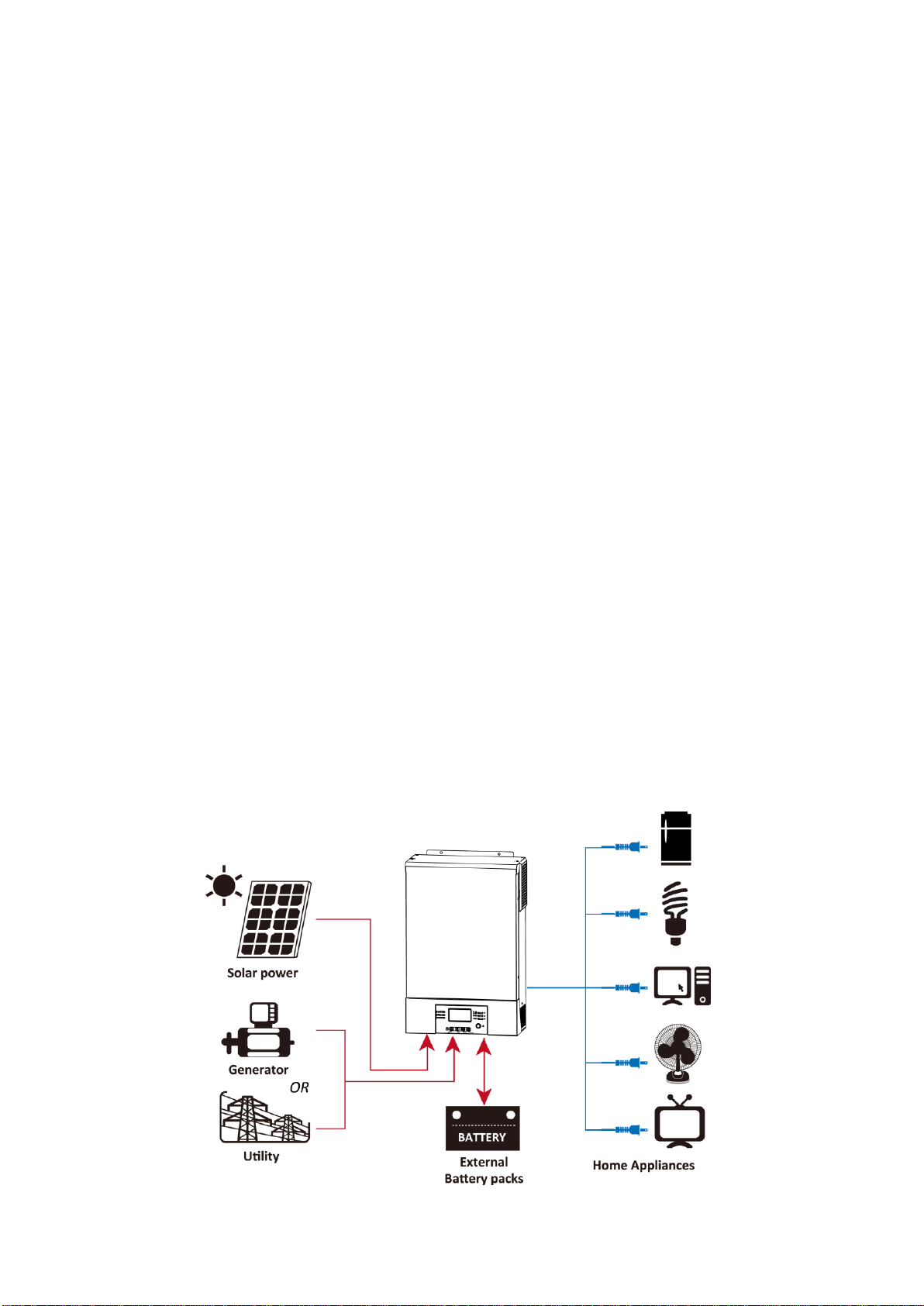
Basic System Architecture...............................................................................................................................2
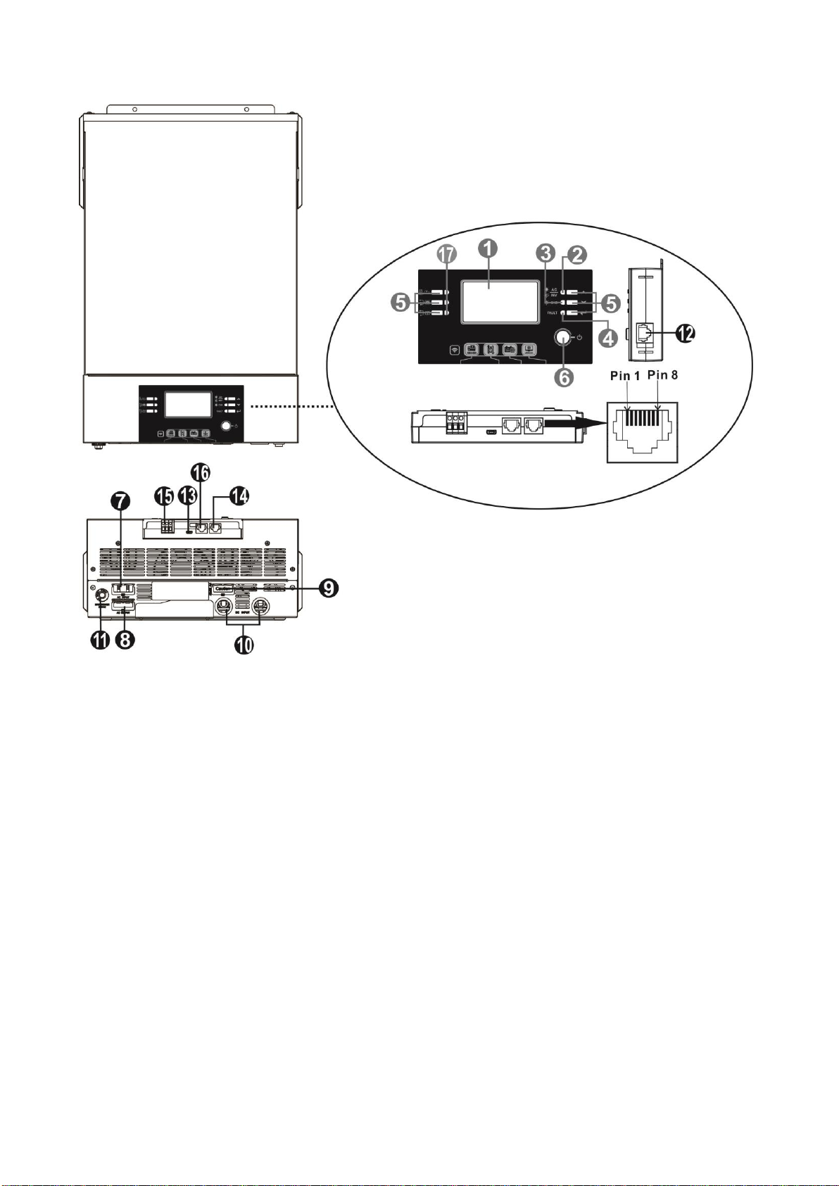
Product Overview.............................................................................................................................................3
INSTALLATION...................................................................................................................................................4
Unpacking and Inspection................................................................................................................................4
Preparation ......................................................................................................................................................4
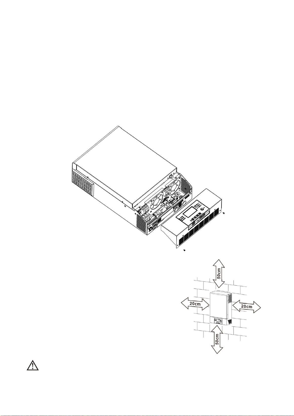
Mounting the Unit.............................................................................................................................................4
Battery Connection ..........................................................................................................................................5
AC Input/Output Connection............................................................................................................................6
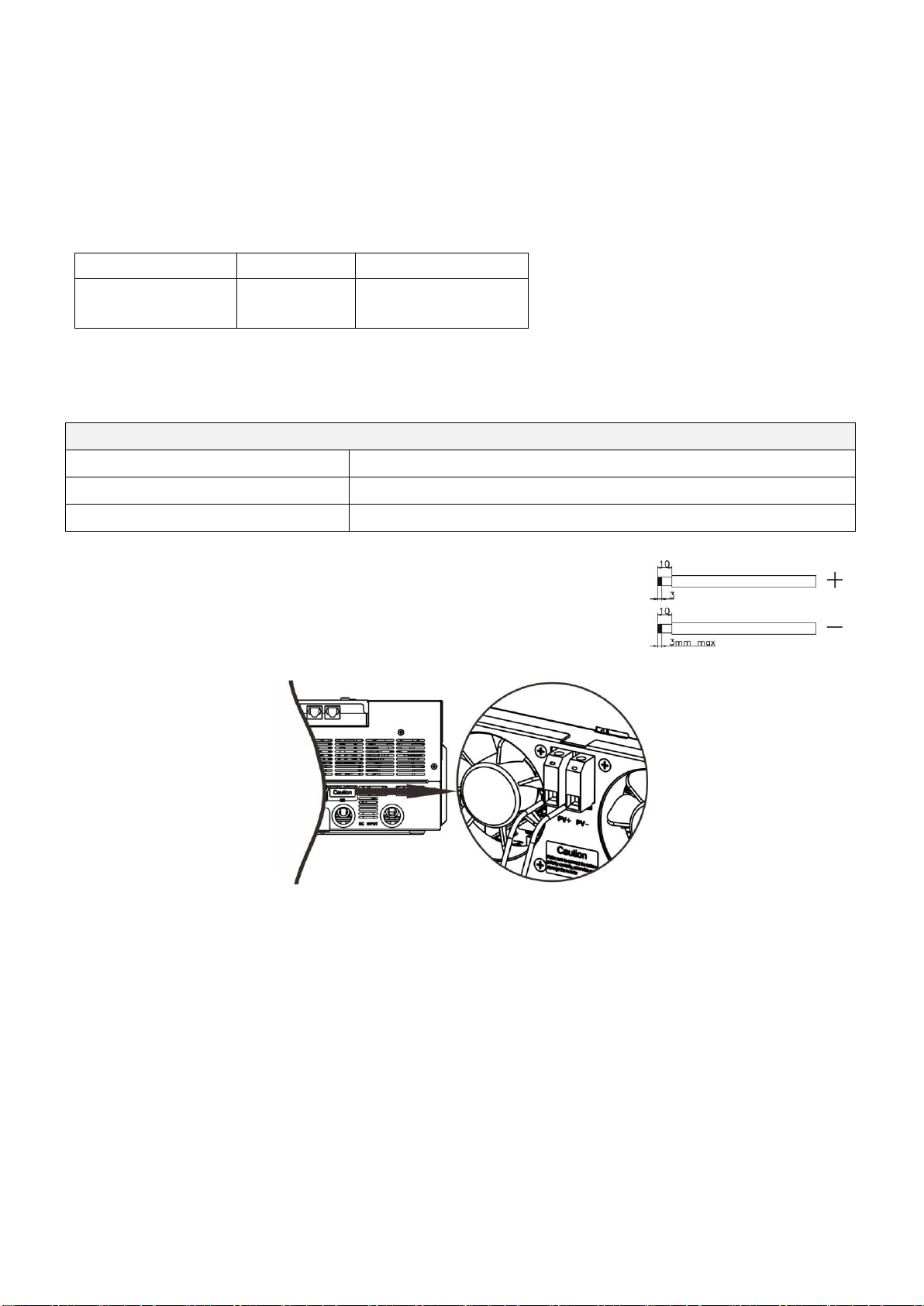
PV Connection.................................................................................................................................................8
Final Assembly.................................................................................................................................................9
Remote Display Panel Installation...................................................................................................................9
Communication Connection...........................................................................................................................11
Dry Contact Signal.........................................................................................................................................11
BMS Communication.....................................................................................................................................11
OPERATION......................................................................................................................................................12
Power ON/OFF ..............................................................................................................................................12
Operation and Display Panel.........................................................................................................................12
LCD Display Icons .........................................................................................................................................13
LCD Setting....................................................................................................................................................15
Display Setting...............................................................................................................................................25
Operating Mode Description..........................................................................................................................29
Fault Reference Code....................................................................................................................................32
Warning Indicator...........................................................................................................................................32
Battery Equalization.......................................................................................................................................33
SPECIFICATIONS.............................................................................................................................................35
Table 1 Line Mode Specifications ...................................................................................................................35
Table 2 Battery Mode Specifications ..............................................................................................................36
Table 3 Charge Mode Specifications ..............................................................................................................37
Table 4 ECO/Bypass Mode Specifications.......................................................................................................38
TROUBLE SHOOTING.....................................................................................................................................39
PARALLEL FUNCTION ....................................................................................................................................40
Appendix A: Approximate Back-up Time Table............................................................................................56
Appendix B: BMS Communication Installation ............................................................................................57
Appendix C: The Wi-Fi Operation Guide in Remote Panel..........................................................................62

1
ABOUT THIS MANUAL
Purpose
This manual describes the assembly, installation, operation and troubleshooting of this unit. Please read
this manual carefully before installations and operations. Keep this manual for future reference.
Scope
This manual provides safety and installation guidelines as well as information on tools and wiring.
SAFETY INSTRUCTIONS
WARNING: This chapter contains important safety and operating instructions. Read and
keep this manual for future reference.
1. Before using the unit, read all instructions and cautionary markings on the unit, the batteries and all
appropriate sections of this manual.
2. CAUTION --To reduce risk of injury, charge only deep-cycle lead acid type rechargeable batteries.
Other types of batteries may burst, causing personal injury and damage.
3. Do not disassemble the unit. Take it to a qualified service center when service or repair is required.
Incorrect re-assembly may result in a risk of electric shock or fire.
4. To reduce risk of electric shock, disconnect all wirings before attempting any maintenance or cleaning.
Turning off the unit will not reduce this risk.
5. CAUTION –Only qualified personnel can install this device with battery.
6. NEVER charge a frozen battery.
7. For optimum operation of this inverter/charger, please follow required spec to select appropriate cable
size. It’s very important to correctly operate this inverter/charger.
8. Be very cautious when working with metal tools on or around batteries. A potential risk exists to drop
a tool to spark or short circuit batteries or other electrical parts and could cause an explosion.
9. Please strictly follow installation procedure when you want to disconnect AC or DC terminals. Please
refer to INSTALLATION section of this manual for the details.
10. Fuses are provided as over-current protection for the battery supply.
11. GROUNDING INSTRUCTIONS -This inverter/charger should be connected to a permanent grounded
wiring system. Be sure to comply with local requirements and regulation to install this inverter.
12. NEVER cause AC output and DC input short circuited. Do NOT connect to the mains when DC input
short circuits.
13. Warning!! Only qualified service persons are able to service this device. If errors still persist after
following troubleshooting table, please send this inverter/charger back to local dealer or service center
for maintenance.

2
INTRODUCTION
This is a multi-function inverter/charger, combining functions of inverter, MPPT solar charger and battery
charger to offer uninterruptible power support with portable size. Its comprehensive LCD display offers
user-configurable and easy-accessible button operation such as battery charging current, AC/solar charger
priority, and acceptable input voltage based on different applications.
Features
Pure sine wave inverter
Built-in MPPT solar charge controller
Configurable input voltage range for home appliances and personal computers via LCD setting
Configurable battery charging current based on applications via LCD setting
Configurable AC/Solar Charger priority via LCD setting
Compatible to mains voltage or generator power
Auto restart while AC is recovering
Overload/ Over temperature/ short circuit protection
Smart battery charger design for optimized battery performance
Cold start function
Zero-transfer Time
Basic System Architecture
The following illustration shows basic application for this inverter/charger. It also includes following devices to
have a complete running system:
Generator or Utility.
PV modules
Consult with your system integrator for other possible system architectures depending on your requirements.
This inverter can power all kinds of appliances in home or office environment, including motor-type appliances
such as tube light, fan, refrigerator and air conditioner.
Figure 1 Hybrid Power System

3
Product Overview
1. LCD display
2. Status indicator
3. Charging indicator
4. Fault indicator
5. Function buttons
6. Power on/off switch
7. AC input
8. AC output
9. PV connectors
10. Battery input
11. Circuit breaker
12. Remote LCD panel communication port
13. USB port: for communication port and USB function port
14. RS-232 communication port
15. Dry contact
16. BMS communication port: CAN and RS232 or RS485
17. LED indicator for USB function settings

4
INSTALLATION
Unpacking and Inspection
Before installation, please inspect the unit. Be sure that nothing inside the package is damaged. You should
have received the following items inside of package:
The unit x 1
User manual x 1
Communication cable x 1
Software CD x 1
Preparation
Before connecting all wirings, please take off bottom cover by removing two screws as shown below.
Mounting the Unit
Consider the following points before selecting where to install:
Do not mount the inverter on flammable construction materials.
Mount on a solid surface
Install this inverter at eye level in order to allow the LCD display
to be read at all times.
The ambient temperature should be between 0°C and 55°C to
ensure optimal operation.
The recommended installation position is to be adhered to the
wall vertically.
Be sure to keep other objects and surfaces as shown in the
right diagram to guarantee sufficient heat dissipation and to
have enough space for removing wires.
SUITABLE FOR MOUNTING ON CONCRETE OR OTHER NON-COMBUSTIBLE SURFACE ONLY.

5
Install the unit by screwing three screws. It’s recommended to use M4 or M5 screws.
Battery Connection
CAUTION: For safety operation and regulation compliance, it’s requested to install a separate DC over-current
protector or disconnect device between battery and inverter. It may not be requested to have a disconnect
device in some applications, however, it’s still requested to have over-current protection installed. Please refer
to typical amperage in below table as required fuse or breaker size.
WARNING! All wiring must be performed by a qualified personnel.
WARNING! It's very important for system safety and efficient operation to use
appropriate cable for battery connection. To reduce risk of injury, please use the
proper recommended cable and terminal size as below.
Recommended battery cable and terminal size:
Typical
Amperage
Battery
Capacity
Wire Size
Ring Terminal
Torque
Value
Cable
mm2
Dimensions
D (mm)
L (mm)
125A/150A
200AH
1*1/0AWG
60
6.4
49.7
2~3 Nm
2*4AWG
44
6.4
49.7
Please follow below steps to implement battery connection:
1. Assemble battery ring terminal based on recommended battery cable and terminal size.
2. Insert the ring terminal of battery cable flatly into battery connector of inverter and make sure the nuts are
tightened with torque of 2-3 Nm. Make sure polarity at both the battery and the inverter/charge is correctly
connected and ring terminals are tightly screwed to the battery terminals.
Ring terminal:

6
WARNING: Shock Hazard
Installation must be performed with care due to high battery voltage in series.
CAUTION!! Do not place anything between the flat part of the inverter terminal and the ring
terminal. Otherwise, overheating may occur.
CAUTION!! Do not apply anti-oxidant substance on the terminals before terminals are
connected tightly.
CAUTION!! Before making the final DC connection or closing DC breaker/disconnector, be sure
positive (+) must be connected to positive (+) and negative (-) must be connected to negative
(-).
AC Input/Output Connection
CAUTION!! Before connecting to AC input power source, please install a separate AC breaker between
inverter and AC input power source. This will ensure the inverter can be securely disconnected during
maintenance and fully protected from over current of AC input. The recommended spec of AC breaker is 50A.
CAUTION!! There are two terminal blocks with “IN” and “OUT” markings. Please do NOT mis-connect input
and output connectors.
WARNING! All wiring must be performed by a qualified personnel.
WARNING! It’s very important for system safety and efficient operation to use appropriate cable for AC input
connection. To reduce risk of injury, please use the proper recommended cable size as below.
Suggested cable requirement for AC wires
Gauge
Torque Value
8 AWG
1.4~ 1.6Nm
Please follow below steps to implement AC input/output connection:
1. Before making AC input/output connection, be sure to open DC protector or disconnector first.
2. Remove insulation sleeve 10mm for six conductors. And shorten phase L and neutral conductor N 3 mm.
3. Insert AC input wires according to polarities indicated on terminal block and tighten the terminal screws. Be
sure to connect PE protective conductor ( ) first.
→Ground (yellow-green)
L→LINE (brown or black)
N→Neutral (blue)

7
CAUTION: Important
Be sure to connect AC wires with correct polarity. If L and N wires are connected reversely, it may cause utility
short-circuited when these inverters are worked in parallel operation.
CAUTION: Important
When input source is the generator, it’s suggested to choose the generator by following parameters:
- The recommend generator rating should be at least 2X of inverter capacity.
- Generator output: Pure Sine Wave
- Generator output voltage rms range: 180 ~ 270Vac
- Generator output frequency range: 45Hz ~ 63Hz
It’s recommended to test the generator with the inverter before the installation. Few generators complied above
parameters may still not be accepted by the inverter as the input source.
WARNING:
Be sure that AC power source is disconnected before attempting to hardwire it to the unit.
4. Then, insert AC output wires according to polarities indicated on terminal block and tighten terminal screws.
Be sure to connect PE protective conductor ( ) first.
→Ground (yellow-green)
L→LINE (brown or black)
N→Neutral (blue)
5. Make sure the wires are securely connected.
CAUTION: Appliances such as air conditioner are required at least 2~3 minutes to restart because it’s required
to have enough time to balance refrigerant gas inside of circuits. If a power shortage occurs and recovers in a
short time, it will cause damage to your connected appliances. To prevent this kind of damage, please check
manufacturer of air conditioner if it’s equipped with time-delay function before installation. Otherwise, this
inverter/charger will trig overload fault and cut off output to protect your appliance but sometimes it still causes
internal damage to the air conditioner.

8
PV Connection
CAUTION: Before connecting to PV modules, please install separately a DC circuit breaker between inverter
and PV modules.
WARNING! All wiring must be performed by a qualified personnel.
WARNING! It'’very important for system safety and efficient operation to use appropriate cable for PV module
connection. To reduce risk of injury, please use the proper recommended cable size as below.
WARNING! Never connect the positive and negative terminals of the solar panel to the ground.
Typical Amperage
Cable Size
Torque
27A
10 AWG
1.2~1.6 Nm
PV Module Selection:
When selecting proper PV modules, please be sure to consider below parameters:
1. Open circuit Voltage (Voc) of PV modules not exceeds max. PV array open circuit voltage of inverter.
2. Open circuit Voltage (Voc) of PV modules should be higher than min. battery voltage.
Solar Charging Mode
INVERTER MODEL
5KW/6KW
Max. PV Array Open Circuit Voltage
500Vdc
PV Array MPPT Voltage Range
120~430Vdc
Please follow below steps to implement PV module connection:
1. Remove insulation sleeve 10 mm for positive and negative conductors.
2. Check correct polarity of connection cable from PV modules and PV input
connectors. Then, connect positive pole (+) of connection cable to positive
pole (+) of PV input connector. Connect negative pole (-) of connection
cable to negative pole (-) of PV input connector.
3. Make sure the wires are securely connected.

9
Final Assembly
After connecting all wirings, please put bottom cover back by screwing two screws as shown on the below
chart.
Remote Display Panel Installation
The LCD panel can be removable and installed in a remote site with an optional communication cable. Please
follow below steps to implement this remote panel installation.
Step 1. Loosen the screw on the two sides of bottom case and push up the case cover. Then, remove screw on
the top of the display panel. Now, the display can be removed from the bottom case. Then, pull out the cable
from the remote communication port.
Step 2. Drill two holes in the marked locations with two screws as shown below chart. Place the panel on the
surface and align the mounting holes with the two screws. Then, use one more screw on the top to fix the panel
to the wall and check if the remote panel is firmly secured.

10
Note: Installation to the wall should be implemented with
the proper screws. Refer chart for recommended spec of
screws.
Step 3. Connect LCD panel to the inverter with an optional RJ45 communication cable as below chart.
M3
Ø 5-Ø 9
RS-232 communication to PC
Remote communication
BMS communication
USB communication to PC

11
Communication Connection
Serial Connection
Please use supplied communication cable to connect to inverter and PC. Insert bundled CD into a computer and
follow on-screen instruction to install the monitoring software. For the detailed software operation, please
check user manual of software inside of CD.
Wi-Fi Connection
This unit is equipped with a Wi-Fi transmitter. Wi-Fi transmitter can enable wireless
communication between off-grid inverters and monitoring platform. Users can access and
control the monitored inverter with downloaded APP. You may find “WatchPower” app
from the Apple®Store or “WatchPower Wi-Fi” in Google®Play Store. All data loggers and
parameters are saved in iCloud. For quick installation and operation, please check
Appendix C.
Dry Contact Signal
There is one dry contact (3A/250VAC) available on the rear panel. It could be used to deliver signal to external
device when battery voltage reaches warning level.
Unit Status
Condition
Dry contact port:
NC & C
NO & C
Power Off
Unit is off and no output is powered.
Close
Open
Power On
Output is powered from Utility.
Close
Open
Output is
powered
from
Battery
power or
Solar
energy.
Program 01
set as USB
(utility first)
Battery voltage < Low DC warning
voltage
Open
Close
Battery voltage > Setting value in
Program 13 or battery charging
reaches floating stage
Close
Open
Program 01
is set as
SBU (SBU
priority) or
SUB (solar
first)
Battery voltage < Setting value in
Program 12
Open
Close
Battery voltage > Setting value in
Program 13 or battery charging
reaches floating stage
Close
Open
BMS Communication
If connecting to lithium battery, it’s requested to buy a special communication cable. For the detailed BMS
communication and installation, please check Appendix B –BMS Communication Installation.

12
OPERATION
Power ON/OFF
Once the unit has been properly installed and the batteries are connected well, simply press On/Off switch
to turn on the unit.
Operation and Display Panel
The operation and display panel, shown in below chart, is on the front panel of the inverter. It includes
three indicators, four function keys and a LCD display, indicating the operating status and input/output
power information.
LCD display
LED Indicators
LED Indicator
Messages
Setting LED1
Green
Solid On
Output powered by utility
Setting LED2
Green
Solid On
Output powered by PV
Setting LED3
Green
Solid On
Output powered by battery
Status
Indicator
Green
Solid On
Output is available in bypass mode
Flashing
Output is powered by battery or AC in inverter mode
Green
Solid On
Battery is fully charged
Flashing
Battery is charging.
Red
Solid On
Fault mode
Flashing
Warning mode
Status
indicators
Function keys
On/off switch
Function keys
Setting LED 3
Setting LED 1
Setting LED 2

13
Function Keys
Function Key
Description
ESC
Exit setting mode
USB function setting
Select USB OTG functions
Up
To last selection
Down
To next selection
Enter
To confirm the selection in setting mode or enter setting mode
LCD Display Icons
Icon
Function description
Input Source Information
Indicates the AC input.
Indicates the PV input
Indicate input voltage, input frequency, PV voltage, charger current,
charger power, battery voltage.
Configuration Program and Fault Information
Indicates the setting programs.
Indicates the warning and fault codes.
Warning: flashing with warning code.
Fault: lighting with fault code
Output Information
Indicate output voltage, output frequency, load percent, load in VA,
load in Watt and discharging current.
Battery Information
Indicates battery level by 0-24%, 25-49%, 50-74% and 75-100% in
battery mode and charging status in line mode.
In AC mode, it will present battery charging status.
Status
Battery voltage
LCD Display
Constant
Current mode /
Constant
Voltage mode
<2V/cell
4 bars will flash in turns.
2 ~ 2.083V/cell
Bottom bar will be on and the other three
bars will flash in turns.
2.083 ~ 2.167V/cell
Bottom two bars will be on and the other two
bars will flash in turns.
> 2.167 V/cell
Bottom three bars will be on and the top bar
will flash.
Floating mode. Batteries are fully charged.
4 bars will be on.

14
In battery mode, it will present battery capacity.
Load Percentage
Battery Voltage
LCD Display
Load >50%
< 1.85V/cell
1.85V/cell ~ 1.933V/cell
1.933V/cell ~ 2.017V/cell
> 2.017V/cell
Load < 50%
< 1.892V/cell
1.892V/cell ~ 1.975V/cell
1.975V/cell ~ 2.058V/cell
> 2.058V/cell
Load Information
Indicates overload.
Indicates the load level by 0-24%, 25-49%, 50-74% and 75-100%.
0%~24%
25%~49%
50%~74%
75%~100%
Mode Operation Information
Indicates unit connects to the mains.
Indicates unit connects to the PV panel.
Indicates load is supplied by utility power.
Indicates the utility charger circuit is working.
Indicates the solar charger circuit is working.
Indicates the DC/AC inverter circuit is working.
Indicates unit alarm is disabled.
Indicates USB disk is connected.
Indicates timer setting or time display

15
LCD Setting
After pressing and holding “”button for 3 seconds, the unit will enter setting mode. Press “ ” or “ ”
button to select setting programs. And then, press “ ” button to confirm the selection or “ ” button to
exit.
Setting Programs:
Program
Description
Selectable option
00
Exit setting mode
Escape
01
Output source priority:
To configure load power
source priority
USB : Utility first (default)
Utility will provide power to the
loads as first priority.
If Utility energy is unavailable,
solar energy and battery
provides power the loads.
SUB: Solar first
Solar energy provides power to
the loads as first priority.
If solar energy is not sufficient
to power all connected loads,
utility energy will supply power
to the loads at the same time.
Battery provides power to the
loads only when solar and utility
is not sufficient.
SBU priority
Solar energy provides power to
the loads as first priority.
If solar energy is not sufficient
to power all connected loads,
battery energy will supply power
to the loads at the same time.
Utility provides power to the
loads only when battery voltage
drops to either low-level
warning voltage or the setting
point in program 12 or solar and
battery is not sufficient.

16
02
Maximum charging current:
To configure total charging
current for solar and utility
chargers.
(Max. charging current =
utility charging current +
solar charging current)
60A (default)
Setting range is from 10A to
120A and increment of each click
is 10A.
05
Battery type
AGM (default)
Flooded
User-Defined
If “User-Defined” is selected,
battery charge voltage and low
DC cut-off voltage can be set up
in program 26, 27 and 29.
Pylontech battery
If selected, programs of 02, 26,
27 and 29 will be automatically
set up. No need for further
setting.
WECO battery
If selected, programs of 02, 12,
26, 27 and 29 will be
auto-configured per battery
supplier recommended. No need
for further adjustment.
Soltaro battery
If selected, programs of 02, 26,
27 and 29 will be automatically
set up. No need for further
setting.
LIb-protocol compatible
battery
Select “ LIb” if using Lithium
battery compatible to Lib
protocol. If selected, programs of
02, 26, 27 and 29 will be
automatically set up. No need for
further setting.

17
05
Battery type
3rd party Lithium battery
If selected, programs of 02, 26,
27 and 29 will be automatically
set up. No need for further
setting. Please contact the
battery supplier for installation
procedure.
06
Auto restart when overload
occurs
Restart disable (default)
Restart enable
07
Auto restart when over
temperature occurs
Restart disable (default)
Restart enable
09
Output frequency
50Hz (default)
60Hz
10
Operation Logic
Automatically (default)
If selected and utility is available,
inverter will work in line mode.
Once utility frequency is
unstable, inverter will work in
bypass mode if bypass function
is not forbidden in program 23.
Online mode
If selected, inverter will work in
line mode when utility is
available.
ECO Mode
If selected and bypass is not
forbidden in program 23,
inverter will work in ECO mode
when utility is available.
11
Maximum utility charging
current
Note: If setting value in
program 02 is smaller than
that in program in 11, the
inverter will apply charging
current from program 02 for
utility charger.
30A (default)
Default setting is 60A and setting
range is 1A, then from 10A to
120A. Increment of each click is
10A.

18
12
Setting voltage point back
to utility source when
selecting “SBU” (SBU
priority) in program 01
Default setting: 46.0V
Setting range is from 44.0V to
57.0V and increment of each
click is 1.0V.
13
Setting voltage point back
to battery mode when
selecting “SBU” (SBU
priority) in program 01
The setting range is from 48.0V to 64.0V and increment of each
click is 1.0V.
Battery fully charged
54.0V (default)
16
Solar energy priority:
To configure solar energy
priority for battery and load
SbL: Solar energy for battery
first
UCB: Allow utility to charge
battery (Default)
Solar energy charges battery
first and allow the utility to
charge battery.
SbL: Solar energy for battery
first
UdC: Disallow utility to charge
battery
Solar energy charge battery first
and disallow the utility to charge
battery.
SLb: Solar energy for load first
UCb: Allow utility to charge
battery
Solar energy provides power to
the load first and also allow the
utility to charge battery.
SLb: Solar energy for load first
UdC: Disallow utility to charge
battery
Solar energy provides power to
the load first and disallow the
utility to charge battery.
Table of contents
Other MasterPower Inverter manuals

MasterPower
MasterPower BETA RHI 6K-48V 1P Series User manual

MasterPower
MasterPower Beta-20K User manual

MasterPower
MasterPower Delta UM Series User manual

MasterPower
MasterPower OMEGA LV Series User manual

MasterPower
MasterPower Omega ESS 5.5KW User manual

MasterPower
MasterPower OMEGA 2.2KW User manual

MasterPower
MasterPower MasterPower 3.6KW User manual

MasterPower
MasterPower OMEGA 2.2KW LS User manual

MasterPower
MasterPower RAI-3K-48ES-5G User manual