MasterPower OMEGA 2.2KW LS User manual

OMEGA
2.2KW LS (Low PV Input Range)
Solar Inverter for Water Pump Version: 1.3
User Manual

Table Of Contents
ABOUT THIS MANUAL ......................................................................................................................................1
Purpose............................................................................................................................................................1
Scope...............................................................................................................................................................1
SAFETY INSTRUCTIONS...................................................................................................................................1
Inspection.........................................................................................................................................................1
Installation........................................................................................................................................................1
Operation .........................................................................................................................................................2
Maintenance ....................................................................................................................................................2
INTRODUCTION.................................................................................................................................................3
Features...........................................................................................................................................................3
Basic System Architecture...............................................................................................................................3
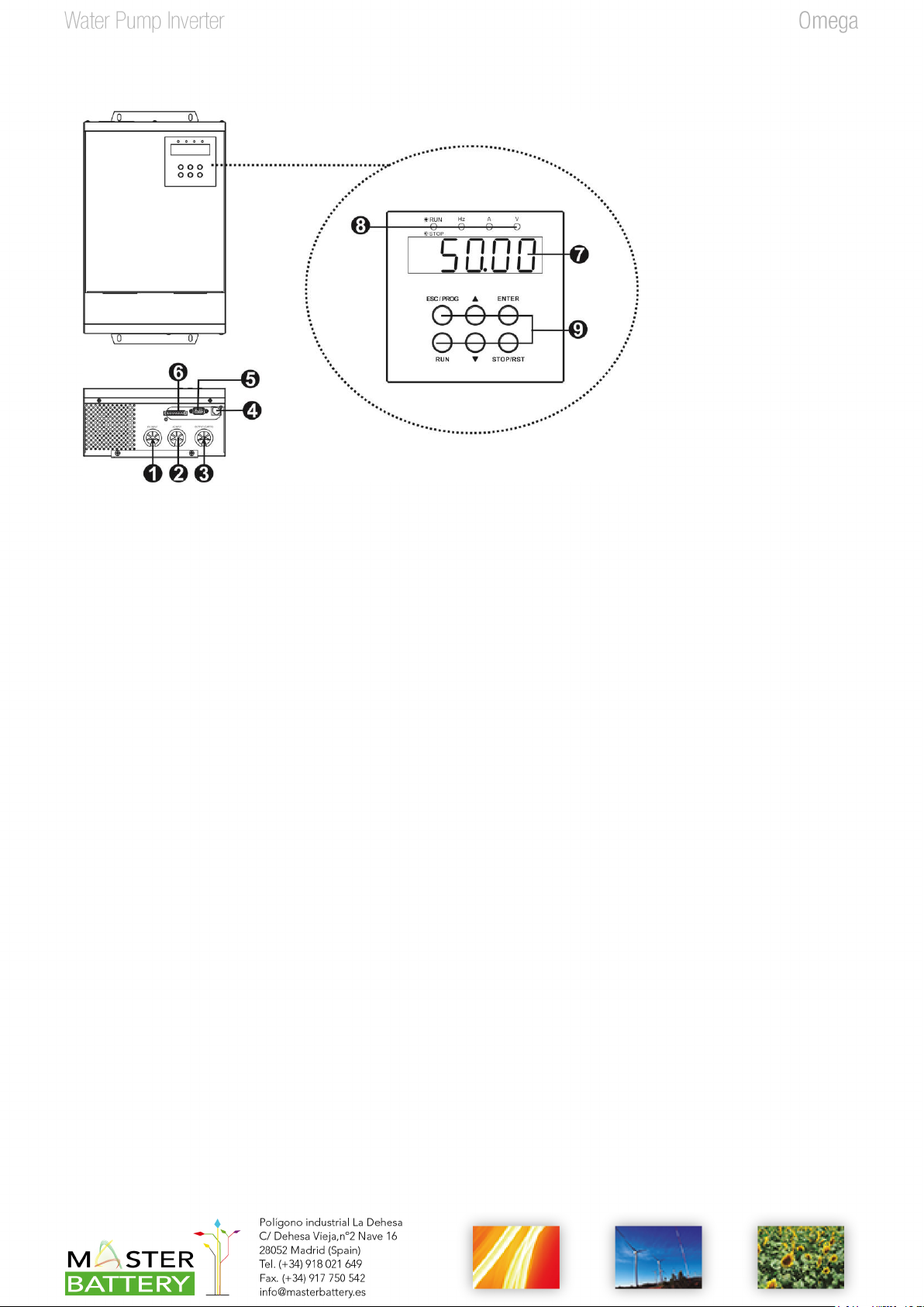
Product Overview.............................................................................................................................................4
INSTALLATION...................................................................................................................................................5
Unpacking and Inspection................................................................................................................................5
Preparation ......................................................................................................................................................5
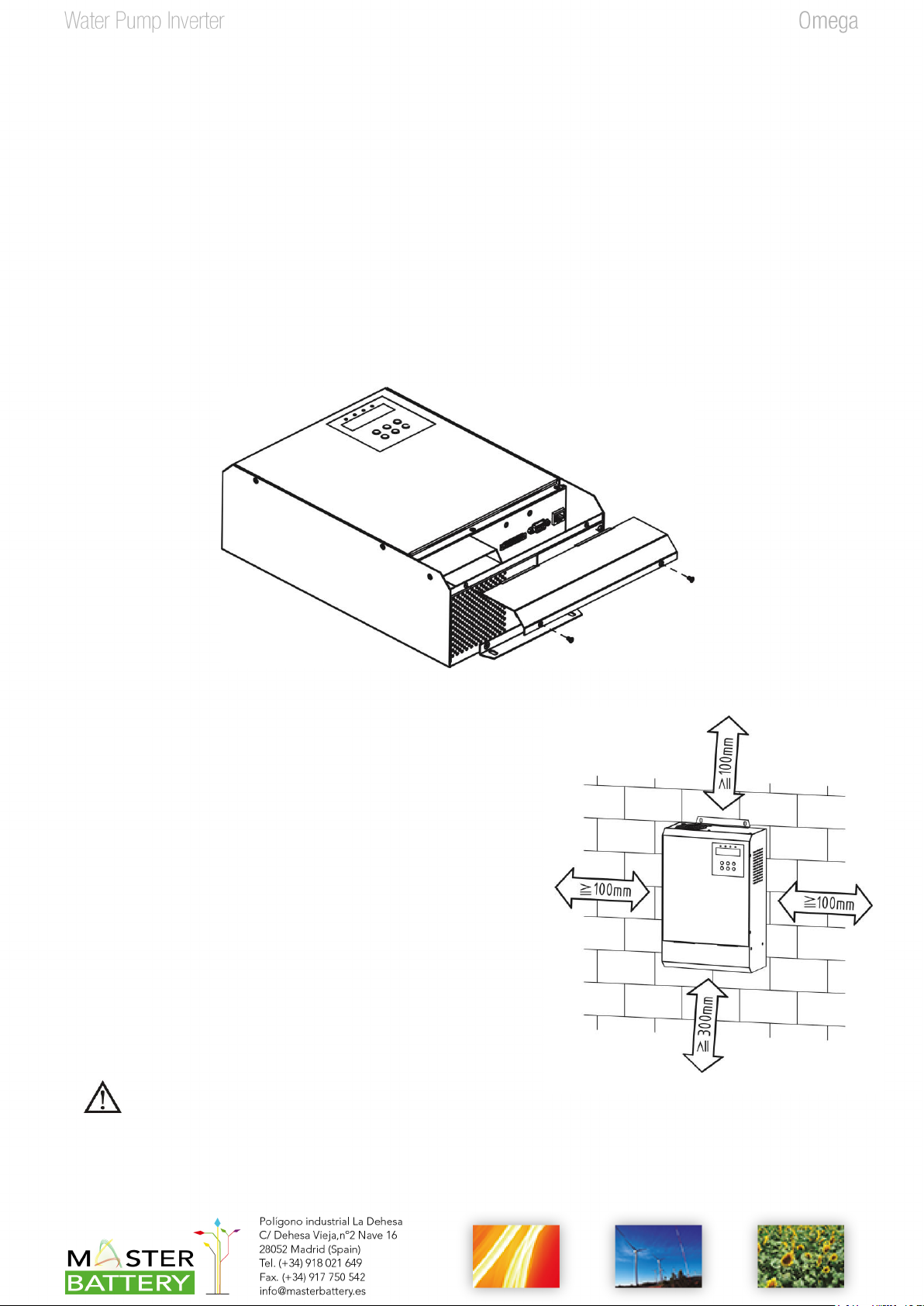
Mounting the Unit.............................................................................................................................................5
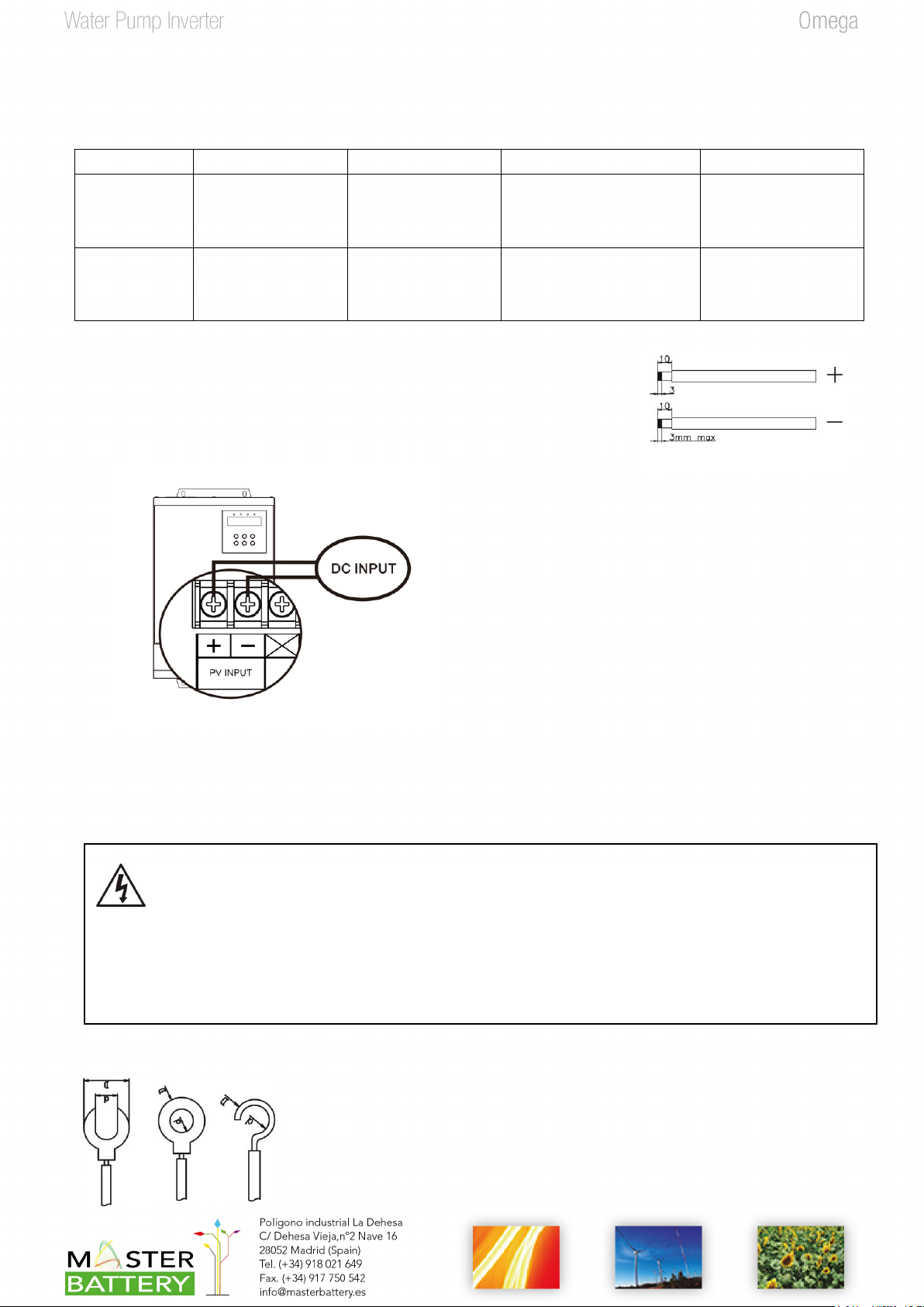
PV Connection.................................................................................................................................................6
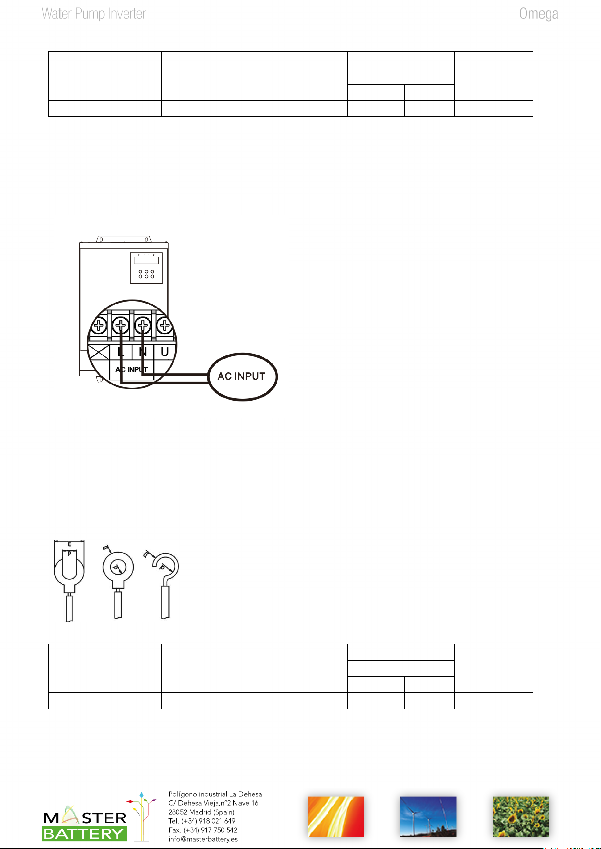
AC Input Connection........................................................................................................................................7
AC Output (Motor) Connection ........................................................................................................................8
Final Assembly.................................................................................................................................................9
Remote Communication Connection.............................................................................................................10
Control Signal Connection (Optional) ............................................................................................................10
COMMISSIONING.............................................................................................................................................11
OPERATION......................................................................................................................................................12
Power ON/OFF ..............................................................................................................................................12
Operation and Display Panel.........................................................................................................................12
Parameter Setting..........................................................................................................................................13
Fault and Warning Code .................................................................................................................................18
Fault Reference Code....................................................................................................................................18
Warning Reference Codes.............................................................................................................................19
SPECIFICATIONS.............................................................................................................................................20

1
ABOUT THIS MANUAL
Purpose
This manual describes the assembly, installation, operation and troubleshooting of this unit. Please read
this manual carefully before installations and operations. Keep this manual for future reference.
Scope
This manual provides safety and installation guidelines as well as information on tools and wiring.
SAFETY INSTRUCTIONS
WARNING: This chapter contains important safety and operating instructions. Read and
keep this manual for future reference.
Inspection
If missing components or damaged inverter is found after receiving, please do NOT install or operate it.
Otherwise, it may cause human injury or equipment damage.
Installation
1. Before installation, please make sure if the voltage range of PV panel and AC input voltage range meet the
requirement.
2. Check if all wires are firmly connected without short circuit. Otherwise, it will cause equipment damage.
3. Do NOT install this inverter under direct sunlight because high temperature may cause equipment damage.
4. Please install the inverter away from inflammable and explosive objectives. Please ensure no liquid can
enter the inverter.
5. Please install the inverter on metal non-combustible surface.
1. CAUTION!! Only qualified personnel can install and operate this inverter.
2. To reduce risk of electric shock, disconnect power source before making wire connection. Otherwise, it may
cause electrical shock.
3. To reduce risk of electric shock, NEVER touch any terminals on electric circuits.
4. If connection cable between inverter and water pump is more than 50m, please be sure to install an AC
reactor. Please choose single phase AC reactor if it’s single phase water pump. Choose three-phase AC
reactor if it’s three-phase water pump. Inductance value for each phase is about 1mH. Otherwise, water
pump would be easily to be damaged.

2
Operation
1. Only after wire connection is complete and put cover back to the inverter, it’s ok to do commissioning.
Otherwise, it will cause electric shock
2. If sunlight is sufficient but little water is pumped, maybe the wires on motor connection are reversely
connected. Please reverse any two wires of them.
3. When testing water pump, be sure to install water pump at appropriate water level. Never allow water
pump in dry running. Otherwise, the inverter will activate protection.
Maintenance
1. Only qualified personnel can maintain, repair, inspect the inverter and replace any components.
2. It may still contain energy after disconnecting power source for 10 minutes. Only service the unit after the
bus voltage is within safe range.

3
INTRODUCTION
Interest in renewable energy has increased over the past few years due to solar power becoming more cost
effective and eco-friendly. This is a solar inverter which allows power to be switched from the DC power
obtained from solar panels to the AC power needed to control the pump. With the renewable solar inverter,
pumps can adapt to solar power sources rather than traditional electrical supplies or generators.
This solar inverter is built-in with MPPT solar charger to maximize solar power. Besides, it is easy to install with
low maintenance cost. It becomes an eco-friendly solution for the rural areas where grid power is expensive
and unreliable.
Besides, this inverter also accepts single-phase AC input. It allows the inverter to automatically switch between
PV power and AC utility to guarantee water pump operation during night time.
Features
Built-in MPPT solar charger
Supports single-phase asynchronous motor or three-phase asynchronous motor
Built-in full protection and self-diagnosis
Soft start function prevents water hammer effect and extends system lifecycle
Comprehensive LCD and LEDs display real-time system status
Remote monitoring through RS-485
Supports single-phase AC input. When PV energy is not sufficient, the inverter will automatically switch
to AC input.
Optional remote panel is available.
Basic System Architecture
This solar inverter is specially designed to power water pump. The following illustration shows basic application
for this inverter. It also includes PV modules and remote float switches to have a complete running system.

4
Product Overview
1. PV input
2. Single-phase AC input
3. AC output
4. RS-485 communication port
5. RS-232 communication port
6. Signal control slot
7. Display screen (Refer to Operation and Display Panel for the details)
8. LED indicators (Refer to Operation and Display Panel for the details)
9. Operation buttons (Refer to Operation and Display Panel for the details)

5
INSTALLATION
Unpacking and Inspection
Before installation, please inspect the unit. Be sure that nothing inside the package is damaged. You should
have received the following items inside of package:
The unit x 1
User manual x 1
RJ45 cable x 1
RS-232 cable x 1
Preparation
Before connecting all wirings, please take off bottom cover by removing two screws as shown below.
Mounting the Unit
Consider the following points before selecting where to install:
Do not mount the inverter on flammable construction
materials.
Mount on a solid metal surface.
Avoid direct sunlight. Be sure the environment is shady and
cool.
Be sure to install the inverter into a box with waterproof and
dustproof.
Install this inverter at eye level in order to allow the LCD
display to be read at all times.
The recommended installation position is to be adhered to
the wall vertically.
Be sure to keep other objects and surfaces as shown in the
diagram to guarantee sufficient heat dissipation and to
have enough space for removing wires.
SUITABLE FOR MOUNTING ON CONCRETE OR
OTHER NON-COMBUSTIBLE SURFACE ONLY.

6
1. Drill four holes in the marked locations with four
screws.
2. Install the unit by screwing four screws. It’s
recommended to use M5 screws.
PV Connection
CAUTION: Before connecting to PV modules, please install separately a DC circuit breaker between inverter
and PV modules. The recommended spec of DC breaker is C16A/2P/750VDC/20KA for 2.2KW LS.
NOTE: It’s required to install PV combiner box when using several PV modules in parallel and series.
PV Module Selection:
When selecting proper PV modules, please be sure to consider below parameters:
1. Open circuit Voltage (Voc) of PV modules not exceeds max. DC voltage (450VDC).
2. Accumulated voltage of connected PV panels should be close to 330V for inverter with 220V output voltage.
To calculate PV module numbers in series (N) and in parallel (M), please follow below formula:
For three-phase output:
Imp>Po/(Kvo x 0.9 x M)
For single-phase output, please use 2 times of PV power rating.
Imp>2 x Po/(Kvo x 0.9 x M)
Po represents the rated output power.
Kvo is equal to 330V/345V/360V for 220V/230V/240V output voltage respectively.
Maximum PV module numbers in series (N) > 330 / Vmp
We strongly recommend the total PV Vmp is around 330Vdc to get the optimum MPPT output.
CAUTION: Important
Before making PV connection, be sure to do the following actions to prevent human injury or machine damage.
1. It’s required to turn off circuit breaker.
2. Make sure connect positive pole (+) of PV input connector in inverter to positive pole (+) of PV modules and
negative pole (-) of PV input connector in inverter to negative pole (-) of PV modules.

7
Below are popular solar panel specifications in the market:
A. 75-A: 75W, Vmp=17.46V, Imp=4.3A, Voc=21.96V
B. 75-B: 75W, Vmp=13.3V, Imp=5.64A, Voc=16.94V
C. 140-A: 140W, Vmp=17.9V, Imp=7.82A, Voc=22.0V
D. 250-A: 250W, Vmp=30.64, Imp=8.16A, Voc=37.38V
Output type
PV Panel 75-A
PV Panel 75-B
PV Panel 140-A
PV Panel 250-A
Three-phase
output
19 pieces in Series
x 2 Strings
(2850W PV Panels)
25 pieces in Series
x 2 Strings
(3750W PV Panels)
19 pieces in Series
(2660W PV Panels)
11 pieces in Series
(2750W PV Panels)
Single-phase
output
19 pieces in Series
x 4 Strings
(5700W PV Panels)
25 pieces in Series
x 3 Strings
(5625W PV Panels)
19 pieces in Series
x 2 Strings
(5320W PV Panels)
11 pieces in Series
x 2 Strings
(5500W PV Panels)
Please follow below steps to implement PV module connection:
1. Remove insulation sleeve 10 mm for positive and negative conductors.
2. Check correct polarity of connection cable from PV modules and PV input
connectors. Then, connect positive pole (+) of connection cable to positive
pole (+) of PV input connector. Connect negative pole (-) of connection
cable to negative pole (-) of PV input connector.
3. Make sure the wires are securely connected.
AC Input Connection
CAUTION: Before connecting to AC power source, please install a separate AC circuit breaker between
inverter and AC utility. It’s recommended to use 25A/2P/230V/4500A circuit breaker.
Recommended terminal types:
CAUTION: Important
Before making AC input connection, be sure to do the following actions to prevent human injury or machine
damage.
1. It’s required to turn off circuit breaker.
2. Make sure to connect single-phase AC input to the L & N input connectors in inverter.

8
Suggested cable requirement:
Model
Typical
Amperage
Wire size
Terminal
Torque Value
Dimensions
d (mm)
D (mm)
2.2KW LS
22A
11 AWG
4.5
9.5
1.3 ~ 1.4 Nm
Please follow below steps to implement AC input connection:
1. Before making AC input connection, be sure to disconnect all circuit breakers or disconnectors first.
2. Remove insulation sleeve 10mm for two conductors. And shorten phase L and neutral conductor N 3 mm.
3. Insert AC input wires according to polarities indicated on terminal block and tighten the terminal screws.
L→LINE (brown or black)
N→Neutral (blue)
4. Make sure the wires are securely connected.
AC Output (Motor) Connection
WARNING! All wiring must be performed by a qualified personnel.
WARNING! It's very important for system safety and efficient operation to use appropriate cable for AC output
connection. To reduce risk of injury, please use the proper recommended terminal and cable size as below.
Recommended terminal types:
Suggested cable requirement:
Model
Typical
Amperage
Wire size
Terminal
Torque Value
Dimensions
d (mm)
D (mm)
2.2KW LS
15A
13 AWG
4.5
9.5
1.3 ~ 1.4 Nm
Please follow below steps to implement AC output connection:
1. Remove insulation sleeve 10mm for two conductors if applying single-phase output or three conductors if
applying three-phase output. And shorten these conductor 3 mm.
2. Please follow below steps to complete output wire connection.

9
Single-phase motor connection
If applying for single-phase output application, please connect AC output U and W terminals to single-phase
motor as shown below:
Three-phase motor connection
NOTE: If sunlight or AC input is normal, but little water is pumped, maybe the output wires on motor
connection are reversely connected. Please reverse any two wires of them.
International standards for motor lead wire
US
Black (BLK)
Red (RED)
Yellow (YEL)
Ground (GND)
International
Gray (GRY)
Black (BLK)
Brown (BRN)
Ground (GND)
3. Make sure the wires are securely connected.
4. Make sure the control setting is matching the real wiring application.
Final Assembly
After connecting all wirings, please put bottom cover back by screwing two screws as shown below.

10
Remote Communication Connection
WARNING: Please do NOT mis-connect the wires between RJ45 and RS485/RS-232 converter.
First, please use one RS485 to RS 232 converter as media converter between inverter and computer. Please
follow below chart for wiring connection between RS485 on the inverter and media converter. It’s necessary to
connect to the utility as power source for the media converter. Then, use supplied RS-232 cable to connect to
converter and computer. After wiring is complete, the media converter will light on and any data transmission
occurs, the indicators for RXD and TXD will flash.
Control Signal Connection (Optional)
There are 7 ports in control signal connection. 2-port on the right side is to power supply for remote panel.
5-port on the left side is to detect water level to prevent water pump from dry running and water tank from
overflow/underflow.
Power Supply for Remote Panel
If using remote panel, please connect these two ports to supply power for remote panel. Please follow user
manual of remote panel for the detailed wire connection.
Remote float switch Detection
Control Signal Port: Internal circuit:

11
Signal Port Status
Signal
Water
level status
Remote Float Switch (1)
Remote Float Switch
(2)
S1
S2
S3
Normal Level
Open
Open
Close
Low Level
Close
Open
Open
High Level
Open
Close
n/a
Remote float switch (1):
It’s to prevent water tank overflow or underflow by sensing a remote float switch in water tank. When water
level is normal, it will keep DI1 & COM2 and DI2 & COM2 in open status. When water level is high in water tank,
it will receive high-level signal (open status on DI1 & COM2 and closed status on DI2 & COM2) from float
switch and stop the inverter. When water tank is in low level, it will receive low-level signal (closed status on
DI1 & COM2 and open status on DI2) from float switch and start up the inverter. This action is only available
when the auto turn-on function is enabled. If the water level is normal, DI1 and COM2 are normally in open
status.
Remote float switch (2):
It’s to prevent the water pump dry running by connecting to remote float switch. The length of connecting wire
should not longer than 50m. If the water level is normal in the well, COM1 and DI3 (S3) is kept in normal close
status. If the water level is low in the well, COM1 and DI3 (S3) will be open status. If open status is detected
for COM1 and DI3 (S3), the inverter will automatically shut down in two seconds and show alarm. If closed
status is detected for COM1 and DI3 (S3) again, the inverter will automatically turn on in two seconds and clear
the alarm. And this automatic turn-on action only be effective when program P4.01 is set up as “1”. If this port
is not connected to water level probe, be sure to connect COM1 and DI3 together. It’s default setting from
factory.
COMMISSIONING
Step 1: Check the following requirements before commissioning:
Ensure all wires are firmly and correctly connected
Use a megger to check insulation of motor and wires
Check if the open circuit DC voltage of PV module meets requirement
Step 2: Switch on DC breaker or AC breaker and provide power to the inverter. Then, LCD screen will show 0.00.
Please set up the parameters of the inverter such as rated power, rated frequency, rated current and rated
voltage. For the detailed setting, please check “Parameter setting” section in Operation chapter.
Step 3: Press “RUN” button to activate the inverter. If the output frequency or water yield is low, it may be
wrong for output wire connection. Please exchange any two wires connected to the motor. Please be sure the
output frequency and water yield are normal. It means the wire connection is correct and complete.

12
OPERATION
Power ON/OFF
Once the unit has been properly installed, simply press “RUN” button (located on the button area) to turn
on the unit.
Operation and Display Panel
The operation and display panel, shown in below chart, is on the top case of the inverter. It includes four
indicators, six function buttons and a display screen, indicating the operating status and input/output
power information.
LED Indicator
LED Indicator Messages
Hz Green Solid On Output frequency value is displayed on the LCD screen.
A Green Solid On Output current value is displayed on the LCD screen.
V Green Solid On Output voltage value is displayed on the LCD screen.
A and VGreen Solid on Output power value is displayed on the LCD screen.
STOP/RUN Green Solid on The inverter is running.
Green OFF The inverter stops.
NOTE: After the inverter is turned on, LED display will show following information in turns: current output
frequency, current output voltage, current output current, current PV voltage and current output
power. After the inverter is turned off, LED display will still show output frequency until it’s 0.
Display screen
Function buttons
LED indicators

13
Function Buttons
Function Button
Description
ESC/PROG
To enter or exit setting mode.
ENTER
To confirm the selection/value in setting mode.
RUN
To turn on the unit, press this button for at least 1 second.
STOP/RST
To turn off the unit, press this button for at least 1 second.
To reset fault message, press this button for at least 1 second.
To increase the setting value.
To decrease the setting value.
and ENTER
Press these two buttons at the same time to move cursor location.
Parameter Setting
The entire display setting program structure is demonstrated as below chart.

14
Parameter setting procedure for water pump
Operation steps
Screen Display
1. Press “ESC/PROG” button for 500ms. Then, it will display “P0” in
display screen.
2. Press “ENTER” button for 500ms, display screen will show as in the
right chart.
3. Press “ENTER” button again to start to set up rated power of the water
pump. Press “ENTER” and “DOWN” buttons to switch cursor location.
Press “UP” or “DOWN” button to change value for rated power. Until it
shows correct rated power, please press “ENTER” button to confirm the
setting.
4. Press “UP” button for 500ms to switch to P0.01 program.
5. Press “ENTER” button to be able to set up rated frequency. Press
“ENTER” and “DOWN” buttons to switch cursor location. Them, press
“UP” or “DOWN” button to change value for nominal frequency. Until it
shows correct nominal frequency, please press “ENTER” button to
confirm the setting.
6. Press “UP” button for 500ms to switch to P0.02 program.

15
7. Press “ENTER” button to be able to set up nominal voltage of the water
pump. Press “ENTER” and “DOWN” buttons at the same time to switch
cursor. Then, press “UP” or “DOWN” button to change value for
nominal voltage. Until it shows correct nominal voltage, please press
“ENTER” button to confirm the setting.
8. Press “UP” button for 500ms to switch to P0.03 program.
9. Press “ENTER” button to be able to set up nominal current of the water
pump. Press “ENTER” and “DOWN” buttons to switch cursor location.
Then, press “UP” or “DOWN” button to change value for nominal
current. Until it shows correct nominal current, please press “ENTER”
button to confirm the setting.
10. Then, all parameters of water pump are set up completely. Press
“ESC/PROG” button to return to P0 level. Please press “ESC/PROG”
button again for 1 second to return to main interface.
11. Set up output setting to match the real wiring. P5.00 for setting
single-phase output or three-phase output.
12. Turn on the inverter by pressing “RUN” button. Then, RUN/STOP LED
will light up and display screen will show inverter information in turns.
CAUTION: Before turning on the inverter, be sure to the wiring connection is matching the P5.00 setting.
Otherwise, it will cause damage on the motor.
NOTE: If it’s requested to have the inverter is automatically turned on every morning, please set up program
P4.01 as “1” in standby mode.

16
Parameter Setting Table
〇: This parameter can be modified no matter the inverter is in operation or off status.
◎:This parameter can be modified only when inverter is turned off and it shows 0.00 Hz in display screen.
Program #
Description
Setting Range
Unit
Default Value
Note
P0 Parameter settings for the motor
P0.00
Nominal power
10-2200
W
2200
◎
P0.01
Nominal
frequency
50/60
Hz
50
◎
P0.02
Nominal voltage
187-264
V
220
◎
P0.03
Nominal current
0.1-60
A
14
◎
P0.04
Upper limit for
frequency
Setting value in
P0.05 –setting value
in P0.01
Hz
50
◎
P0.05
Low limit for
frequency
6 –setting value in
P0.04
Hz
10
◎
P1 Over-current device on the motor and torque increasing
P1.00
Maximum
current limit
10-200
%
110
A multiple of
nominal current
〇
P1.01
Kp for max.
current control
50-6000
None
1000
〇
P1.02
Ki for max.
current control
5-1000
None
100
〇
P1.03
60S overload
protection
110-250
%
150
◎
P1.04
Overload
protection on
motor
110-250
%
250
◎
P1.05
Voltage for
torque
increasing
0-10
%
0
Percentage of
nominal voltage
P2 PV DC voltage setting
P2.00
Over DC voltage
protection
Setting value in
P2.01 - 450
V
450
◎
P2.01
Under DC
voltage
protection
90 –Setting value in
P2.00
V
90
◎
P2.02
PV reference
voltage
Setting value in
P2.01 –setting value
in P2.00
V
330
〇

17
Program #
Description
Setting Range
Unit
Default Value
Note
P3 Protection setting for the inverter of the water pump
P3.00
Sleep mode while PV
energy is weak
10-3600
S
120
〇
P3.01
Sleep mode for dry
running
10-7200
S
1200
〇
P3.02
Allow dry pumping
duration
1-3600
S
5
〇
P3.03
Over temperature fault
on inverter
setting value in
P3.04 ~ 100
°C
85
◎
P3.04
Over temperature
warning on inverter
10 ~ setting value in
P3.03
°C
75
〇
P3.05
Acceleration time for
motor
1-3600
S
20
◎
P3.06
Deceleration time for
motor
1-3600
S
20
◎
P3.07
Over-temperature
warning for environment
10-60
℃
45
〇
P4 Inverter operation mode setting
P4.00
MPPT function
enable/disable
0:Disable.
Control PV voltage
in setting value of
P2.02
1:Enable
None
1
◎
P4.01
Auto turn-on
0:Disable
1:Enable
None
0
◎
P4.02
Dry-pumping protection
enable/disable
0:Disable
1:Enable
None
1
〇
P5 Output setting
P5.00
Three-phase or
single-phase output
setting
0000: Single-phase
output
1111: Three-phase
output
None
0000
◎
P5.01
Remote monitored device
ID setting
1 ~ 247
None
1
〇
P5.02
Restore to default setting
0:No
1:Yes
None
0
◎

18
Fault and Warning Code
All fault and warning codes can be reset by pressing “RST” button except for A07 and A11. When faults or
warning occur, press “RST” button and the inverter will enter standby mode. Please press “RUN” button to turn
on the inverter for operation again.
After A02 or A03 warning occurs, the inverter will auto restart operation after a period of sleep mode. If
pressing “RST” button during sleep mode, please be sure to press “RUN” button again for operation.
Fault Reference Code
Fault code
Fault type
Possible Cause
E01
Time out for BUS soft start
The resistor of soft start is broken.
E02
Soft start relay fault
The soft start relay is broken.
E03
Over voltage in output
1. Inverter control is abnormal.
2. Detection is interfered.
E04
Over current in output
1. Output short circuited.
2. The motor is suddenly locked.
3. The motor is abnormal.
E05
Output voltage RMS High
Inverter control is abnormal.
E06
High PV voltage
1. PV input voltage is too high.
2. There is something wrong with voltage
detection circuit.
E07
Current unbalance
1. Output phase loss
2. Output wire is short to the earth.
3. The motor is abnormal.
E09
Over Temperature
1. IGBT temperature is too high
2. The wire of IGBT temperature detection is not
connected.
E10
Over current.
1. Output short circuited.
2. The motor is suddenly locked.
3. Inverter connects to single phase motor but LCD
output setting is three-phase output.
E11
Instantaneous Bus voltage over
1. Pump intrusion.
2. PV voltage is too high.
E12
Current detect fault
Current detection circuit is abnormal.
E13
Output voltage detect fault
Voltage detection circuit is abnormal.
E14
NTC0 no connect
Heatsink detected wire is not connected.
E15
NTC1 no connect
Environment temperature detected wire is not
connected.
E16
Output setting is wrong.
P5.00 parameter setting is wrong.
E17
AC input relay fault.
AC input relay is broken.
E18
Bus voltage over 450 VDC
1. PV voltage is too high.
2. AC input voltage is too high.
Table of contents
Other MasterPower Inverter manuals

MasterPower
MasterPower OMEGA LV Series User manual

MasterPower
MasterPower Delta UM Series User manual

MasterPower
MasterPower Beta-20K User manual

MasterPower
MasterPower BETA RHI 6K-48V 1P Series User manual

MasterPower
MasterPower Omega ESS 5.5KW User manual

MasterPower
MasterPower OMEGA 2.2KW User manual

MasterPower
MasterPower MasterPower 3.6KW User manual

MasterPower
MasterPower MF-OME-X-6KV2 User manual

MasterPower
MasterPower RAI-3K-48ES-5G User manual