entrapment protection wiring
7
Typical Wiring For:
Normally Closed (N.C.)
Photo Cell to EDGE 1
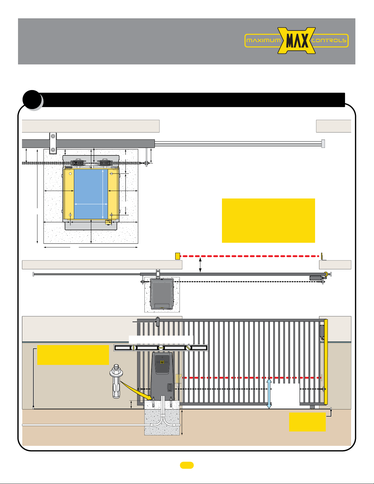
Entrapment Protection Device Locations:
Typical HARDWiring For:
Normally Closed (N.C.)
Sensing Edge to EDGE 1
(CLOSING Direction ONLY)
IMPORTANT Sensing
devices MUST be
powered by MC-200
or they will NOT be
MONITORED.
EDGE 1: MONITORED CLOSE ONLY
Photo Cell: LEARNED MONITORED OPEN/CLOSE
Edge 2: LEARNED MONITORED OPEN/CLOSE
IMPORTANT: Photocells
MUST be in alignment
or fault will occur.
NOTE: See manual for more
information about learned
monitored inputs.
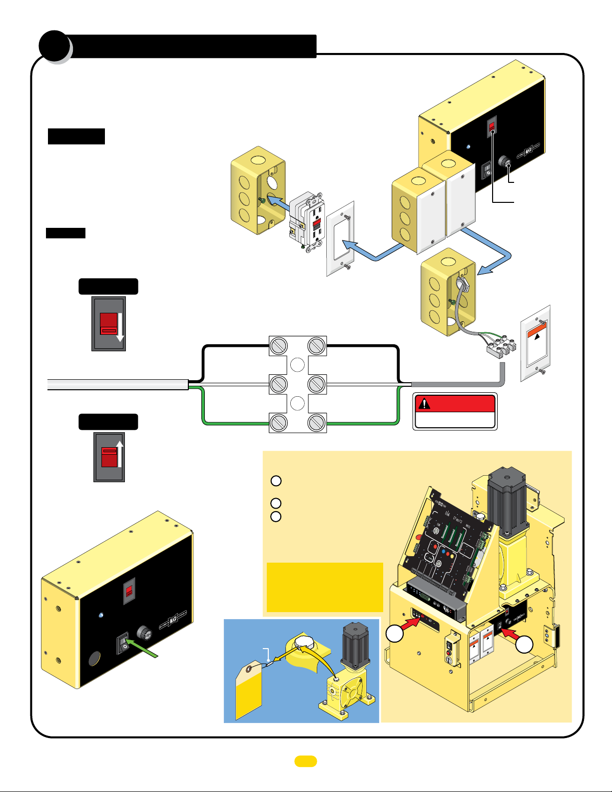
NOTE:
Matrix 1 MUST be
removed to wire
MC-200. See pages 18-20
for specific
photocell wiring.
See page 21 to wire a Gate
Link wireless transmitter.
NOTE: See manual for more information about
photcell and sensing edges installation and wiring.
PhotoCell Edge
UL
Entrap
1
2
Limit SW
ON-LINE
MATRIX JOG JOG
LEFT RIGHT
Jog LT
Jog RT
GND
Edge 1
Edge 2
Photo
Cell
ERD
Motor
OverLoad
POWER
MC-200
Motor Controller
1615 14 1312
3
45
MAX
LED ON
Sensitivity
Edge
ERD Sensor Wire
Jumper UNUSED Entrapment Protection
Inputs to GND or a fault will occur.
Example: Inputs 2 & 3
are NOT used and MUST
be jumpered to GND.
1
2
3
GND
1
23
Photo
Edge 2
EDGE 1
PhotoCell Edge
UL
Entrap
1
2
Limit SW
ON-LINE
MATRIX
JOG JOG
LEFT RIGHT
Jog LT
Jog RT
GND
Edge 1
Edge 2
Photo
Cell
ERD
Motor
OverLoad
POWER
MC-200
Motor Controller
1615 14 1312
3
45
MAX
LED ON
Sensitivity
Edge
ERD
MOTOR Power In
ALARM
BATTERY
PACK
LIMIT
SWITCH
MOTOR
INPUTS
PWR12V
-
GND
-
-
-
PWR 24V -
GND -
RS-485 (-) -
RS-485 (+) -
MATRIX 1
Edge 1
Monitored
Reversing
Edge
Monitored
Photo
Cell
OR
GND
Jog RT
Jog LT
Entrapment Protection
Inputs:
MUSTjumper
unused inputs
Entrapment Protection
SensorGuidelines
1
-
-
-
CAUTION:
See installation instructions.
ATTENTION:
Voir la notice d’installation.
Edge 2
Photo Cell
MC-200 PWR 12V MUSTbe used
ONLYpower entrapment protection
sensors withMC-200 PWR 12V
2
3
•
Asensor MUST be wired to EDGE1 or
operator WILL NOTfunction.
•
Wire NORMALLYCLOSED(N.C.)
MONITOREDsensors ONLY, to each
operator’s MC-200 when dual operators
are used.
•
Reversing Edge and/or Photo Cell can
b
e wired to ANY of the 3 Inputs.
•
MC-200 PWR12V MUSTbe used to
p
ower MONITORED sensors.
•
UNUSED inputs MUST remain
JUMPEREDor fault will occur.
GND
1
2
3
Inputs &MUST be “LEARNED”
to MONITORsensors.
To LEARNinputs &:
1.
MONITORED Sensors MUST be
wired to inputsBEFORE they canbe
learned.Any unusedinputsMUSTbe
jumpered.
2.Reversing Edge and/or PhotoCell can
bewiredtoeither input2or 3.
3.P ressand HOLD the OPEN &STOP
buttons atthe same timeon Matrix 1
until beep isheard,learn mode begins.
Learn mode lastsfor 5 min.indicated
bybeeping.
4.
LEDs WILL beON for eachdetected
sensor onMC-200.LEDsWILL beON
f
or BOTHMC-200swhendual
operators are used.
5.
PressSTOP button again within 5min.
tolearn sensors andendlearn mode,
beepingstops.
Inputsare now MONITORED.
23
23
OPEN STOP
CLOSE
MOTORMOTION
MC-200Slide
EDGE 1 (N.C.)
CLOSING Direction ONLY
GND (C)
Reflector
GND
PWR 12V
Polarity does NOT matter
Thru-Beam
Recr Trans
Reflective
Beam
Power
Power Power
PhotoCell Edge
UL
Entrap
1
2
LimitSW
ON-LINE
MATRIX
JOG JOG
LEFT RIGHT
Jog LT
Jog RT
GND
Edge 1
Edge 2
Photo
Cell
ERD
Motor
OverLoad
POWER
MC-200
Motor Controller
1615 14 1312
3
45
MAX
LED ON
Sensitivity
Edge
ERD
MOTOR Power In
ALARM
BATTERY
PACK
LIMIT
SWITCH
MOTOR
INPUTS
PWR12V
-
GND
-
-
-
PWR 24V -
GND -
RS-485 (-) -
RS-485 (+) -
MATRIX 1
Edge 1
Monitored
Reversing
Edge
Monitored
Photo
Cell
OR
GND
Jog RT
Jog LT
Entrapment Protection
Inputs:
MUSTjumper
unused inputs
Entrapment Protection
SensorGuidelines
1
-
-
-
CAUTION:
See installation instructions.
ATTENTION:
Voir la notice d’installation.
Edge 2
Photo Cell
MC-200 PWR 12V MUST be used
ONLYpower entrapment protection
sensors withMC-200 PWR 12V
2
3
•
Asensor MUST be wired to EDGE1 or
operator WILL NOTfunction.
•
Wire NORMALLYCLOSED(N.C.)
MONITOREDsensors ONLY, to each
operator’s MC-200when dual operators
are used.
•
Reversing Edge and/or Photo Cell can
be wired to ANY of the 3Inputs.
•
MC-200 PWR12VMUSTbe used to
power MONITORED sensors.
•
UNUSED inputs MUST remain
JUMPEREDor fault will occur.
GND
1
2
3
Inputs &MUST be “LEARNED”
to MONITORsensors.
To LEARNinputs &:
1.
MONITOREDSensors MUSTbe
wiredtoinputs BEFORE they canbe
learned.Any unusedinputsMUST be
jumpered.
2.
ReversingEdgeand/orPhotoCell can
bewiredtoeither input2or 3.
3.
PressandHOLD theOPEN &STOP
buttonsatthe same timeonMatrix1
until beep is heard,learn modebegins.
Learn modelastsfor 5min.indicated
bybeeping.
4.
LEDs WILL beON for eachdetected
s
ensor onMC-200.LEDsWILL beON
f
or BOTHMC-200swhendual
operators are used.
5.
PressSTOP button again within 5min.
tolearn sensors andendlearn mode,
beepingstops.
Inputs are nowMONITORED.
23
23
OPEN STOP
CLOSE
MOTORMOTION
MC-200Slide
GEM-104 MUST be used.
EDGE 1 (N.C.)
CLOSING Direction ONLY
GND (C)
GND
PWR 12V
Polarity does NOT matter
ON = Obstruction
BLINKING = Fault
PWR
MON.
SAFETY
INPUT
GEM - 104
10K Edge
Normally
Closed
Sensing Edge
ONE Entrapment protection sensor MUST be installed or operator will
NOT function. It MUST be MONITORED and NORMALLY CLOSED (N.C.).
UL 325 2016 Standard
Beam: 5” or LESS
from CLOSED gate.
Run conduit to operator
Entrapment Area
CLOSING Direction
Photocell
Wall
Gate Closed
Outside Property
Inside Property
Continued on next page.
IMPORTANT: Photocells MUST
be in alignment or fault will occur.
NOTE: Photo input on Matrix 1 is NOT
MONITORED (Normally OPEN) and is
NOT UL 325 entrapment protection.
CLOSING direction photocell
to MC-200 EDGE 1 input.
IMPORTANT: Entrapment
Protection Photocells MUST be
Monitored Normally Closed Type.
6
UL 325 2016 Standard-MAX 1700FS Quick Install Rev 3