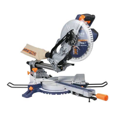
MaxPro PROFESSIONAL MPBMS255L User manual

PROFESSIONAL
MPBMS255L
Mitre saw 1-10
GB
Scie à onglets 11-21
FR
Sierra Ingletadora 22-32
ES
33-43
RU
www.maxpro-tools.com
2021-10
DECLARATION OF CONFORMITY
MPBMS255L
EN 61029-1:2009 EN 61029-2-9:2009 EN 60825-1:2007
2006/42/EC, 2014/35/EU, 2004/108/EC, 2011/65/EU,2012/19/EU
Chief Ex ve Officer:
KREBS GmbH D-72124 PLIEZHAUSEN
09-17-2015
We declare under our sole responsibility that this product is in conformity with the following standards
GB CE DECLARATION OF CONFORMITY
Nous déclarons sous notre propre responsabilité que ce produit est en conformité avec les normes ou
documents normalisés suivants:
FR DÉCLARATION DE CONFORMITE CE
Declaramos bajo nuestra sola responsabilidad que este producto está en conformidad con las normas o
documentos normalizados siguientes:
ES DECLARACIÓN DE CONFORMIDAD CE
Мы с полной ответственностыо заявляем, что это изделие соответствует следующим стандартам
или станда ртизованным документам:
RU ДЕКЛАРАЦИЯ О СООТВЕТСТВИИ СТАНДАРТАМ CE


1GB
TECHNICAL DATA
Model MPBMS255L
Arcle code 113-0302
Voltage 220-240V~ 50/60Hz
Rated power input 1800W
No-load speed 4500/min
Saw blade diameter 255mm
Base Material Aluminium
Cung Capacity
0°/90° H75 × W135mm
0°/45° H45× W135mm
45°/90° H75× W95mm
45°/45° H45× W95mm
Swivel Cung Funcon Le
Laser Funcon Y
Cable Rubber
Cable length 2M
Weight according to EPTA-Procedure 01/2003 10.1 KG
Noise/Vibraon Informaon
LpA sound pressure level 93dB(A)
LWA sound power level 106dB(A)
Uncertainty 3 dB(A)
Vibraon emission value 4.19m/s²
Uncertainty 1.5 m/s²
The vibraon emission level given in this informaon sheet has been measured in accordance with a
TECHNICAL DATA................................................................................................................................. 1
APPLICATION....................................................................................................................................... 2
WARNING............................................................................................................................................ 2
SYMBOLS............................................................................................................................................. 2
GENERAL SAFETY................................................................................................................................. 3
SAFETY INSTRUCTION ......................................................................................................................... 4
OPERATING INSTRUCTION.................................................................................................................. 6
CLEANING AND MAINTENENCE.......................................................................................................... 10
ENVIRONMENT.................................................................................................................................... 10
Contents

WARNING
2
GB
standardised test given in EN 60129 and may be used to compare one tool with another. It may be used for
a preliminary assessment of exposure.
The declared vibraon emission level represents the main applicaons of the tool. However if the tool is
used for different applicaons, with different accessories or poorly maintained, the vibraon emission may
differ. This may significantly increase the exposure level over the total working period.
An esmaon of the level of exposure to vibraon should also take into account the mes when the tool is
switched offor when it is running but not actually doing the job. This may significantly reduce the exposure
level over the total working period.
Idenfy addional safety measures to protect the operator from the effects of vibraon such as: maintain
the tool and the accessories, keep the hands warm, organisaon of work paerns.
APPLICATION
This tool is intended as a staonary machine for performing length ways and cross ways straight cuts in
wood ( and light aluminum with a special blade for aluminum ) also possible are horizontal miter angles of
45° (le side) to 45° (right side) as well as vercal bevel angles of 45° (le side).
are devoted to connuously improving and perfecng the exisng products.
Therefore,the technical performance and design concept of products may vary without any prior noce;
Our apology for any possible incurrence of inconvenience therefore.
Read and follow the operang instrucons and safety informaon before using for the first me. Save this
manual.
When using electric tools basic safety precauons should always be followed to
reduce the risk of fire, electric shock and personal injury including the following.
Read all these instrucons before aempng to operate this product and save these instrucons.
The use of any accessory or aachment other than one recommend in this instrucon manual may present
a risk of personal injury.
Packing materials are no toys! Children must not play with plasc bags! Danger of suffocaon!
Remove the plug from the socket before carrying out any adjustment, servicing or maintenance.
Read all safety warnings and all instrucons. Failure to follow the warnings and instrucons may result in
electric shock, fire and/or serious injury.
Make sure the voltage corresponds to the type label on the unit.
The power tool noise output may exceed 85dB(A) at the workplace. In this instance, wear ear protecon.
Read the manual Wear ear protecon
Warning Wear dusk mask
Do not dispose of old appliances in the
household garbage
Disconnect from power supply while
maintance
Double isulaon
Wear eye protecon
SYMBOLS

3GB
GENERAL SAFETY
Warnings !
Read all safety warnings and all instrucons. Failure tofollow the warnings and instrucons may result in
electric shock, fire and/or serious injury.
Save all warnings and instrucons for future reference.
The term “power tool” in the warnings refers toyour mains-operated (corded) power tool or baery-
operated (cordless) power tool.
1)Work area safety
a) Keep work area clean and well lit. Cluered or dark areas invite accidents.
b) Do not operate power tools in explosive atmospheres, such as in the presence of flammable liquids,
gases or dust. Power tools create sparks which may ignite the dust or fumes.
c) Keep children and bystanders away while operang a power tool. Distracons can cause you tolose
control.
2) Electrical safety
a) Power tool plugs must match the outlet. Never modify the plug in any way. Do not use any adapter
plugs with earthed (grounded) power tools. Unmodified plugs and matching outlets will reduce risk of
electric shock.
b) Avoid body contact with earthed or grounded surfaces, such as pipes, radiators, ranges and
refrigerators. There is an increased risk of electric shock if your body is earthed or grounded.
c) Do not expose power tools to rain or wet condions. Water entering a power tool will increase the risk
of electric shock.
d) Do not abuse the cord. Never use the cord for carrying, pulling or unplugging the power tool. Keep
cord away from heat, oil, sharp edges and moving parts. Damaged or entangled cords increase the risk of
electric shock.
e) When operang a power tool outdoors, use an extension cord suitable for outdoor use and so marked.
Use of a cord suitable for outdoor use reduces the risk of electric shock.
f) If operang a power tool in a damp locaon is unavoidable, use a residual current device (RCD)
protected supply. Use of an RCD reduces the risk of electric shock.
g) Inspect tool cords periodically and replace if damaged by a authorized service facility.
h) Inspect extension cords periodically and replace if damage.
3) Personal safety
a) Stay alert, watch what you are doing and use common sense when operang a power tool. Do not use
a power tool while you are red or under the influence of drugs, alcohol or medicaon.A moment of
inaenon while operang power tools may result in serious personal injury.
b) Use always protecve equipment. Always wear eye protecon, dust mask, hearing protectors and
safety shoes. By service on machine or raw materials use gloves. Keep your hair back. Reduce changes on
personal injury..
c) Prevent unintenonal starng. Ensure the switch is in the off-posion before connecng topower source
and/or baery pack, picking up or carrying the tool or servicing and maintaining the tool. Carrying power
tools with your finger on the switch or energizing power tools that have the switch on invites accidents.
d) Remove any adjusng key or wrench before turning the power tool on. A wrench or a key leaached
to a rotang part of the power tool may result in personal injury.
e) Do not overreach. Keep proper foong and balance at all mes.This enables beer control of the
power tool in unexpected situaons.
f) Dress properly. Do not wear loose clothing or jewelry. Keep your hair, clothing and gloves away from

4
GB
moving parts. Loose clothes, jewelry or long hair can be caught in moving parts.
g) If devices are provided for the connecon of dust extracon and collecon facilies, ensure these are
connected and properly used. Use of dust collecon can reduce dust-related hazards.
h) Keep handles dry, clean and free from oil and grease.
i) Follow instrucons for lubricaon and changing accessories.
4) Power tool use and care
a) Do not force the power tool. Use the correct power tool for your applicaon. The correct power tool
will do the job beer and safer at the rate for which it was designed.
b) Do not use the power tool if the switch does not turn it on and off. Any power tool that cannot be
controlled with the switch is dangerous and must be repaired.
c) Disconnect the plug from the power source and/or the baery pack from the power tool before
making any adjustments, changing accessories, or storing power tools. Such prevenve safety measures
reduce the risk of starng the power tool accidentally.
d) Store idle power tools out of the reach of children and do not allow persons unfamiliar with the power
tool or these instrucons to operate the power tool. Power tools are dangerous in the hands of untrained
users.
e) Maintain power tools. Check for misalignment or binding of moving parts and guards, breakage of
parts and any other condion like switches, that may affect the power tool’s operaon. If damaged, have
the power tool repaired by authorized service center before use. Many accidents are caused by poorly
maintained power tools.
f) Keep cung tools sharp and clean. Properly maintained cung tools with sharp cung edges are less
likely to bind and are easier to control.
g) Use the power tool, accessories and tool bits etc. in accordance with these instrucons, taking into
account the working condions and the work to be performed. Use of the power tool for operaons
different from those intended could result in a hazardous situaon.
h) Secure the work piece. Always clamp work piece with clamping devices, this is much safer than by
hand.
I) Use the right tool for right job, do not force small tools to do the job of a heavy duty tool and do not
use tools for purposes not intended. For example do not use a circular saw to cut tree limbs or logs.
5) Service
a) Have your power tool serviced by a qualified repair person using only idencal replacement parts. This
will ensure that the safety of the power tool is maintained, otherwise this may result in considerable
danger to the user.
SAFETY INSTRUCTION
Symbols
Observe the dimensions of the saw blade. The hole diameter must match the tool
spindle without play.
Danger Area! Keep hands far away from the cung area while the machine is running.
Keep bystanders away.

5GB
GENERAL
1. Only use this tool for cung wood, cung aluminum is possible only with a special separate saw blade.
2. Always saw asingle work piece (work pieces placed one on the other or next to each other cannot be
properly clamped which may result in saw blade binding or work piece slipping during sawing).
3.Inrush currents cause short-me voltage drops; under unfavorable power supply condions, other
equipment may be affected (if the system impedance of the power supply is lower than 0,295 + j0,184
Ohm, disturbances are unlikely to occur); if you need further clarificaon, you may contact your local power
supply authority.
4.Always disconnect plug from power source before making any adjustment or changing any accessory.
5.This tool should not be used by people under the age of 16 years.
6.This tool is not suitable for wet cung.
OUTDOOR USE
When used outdoors, connect the tool viaafault current (FI)circuit breaker with atriggeringcurrent of
30 mA maximum, and only use an extension cord which is intended for outdoor use and equipped with a
splash proof coupling-socket.
BEFORE USE
1.Always check that the supply voltage is the same as the voltage indicated on the nameplate of the tool.
2.Use completely unrolled and safe extension cords with a capacity of 16 Amps (U.K. 13 Amps).
3.Always mount the tool on a flat and stable working surface (e.g. workbench).
4.Wear protecve glasses, hearing protecon, and protecve gloves.
5.Dust from material such as paint containing lead, some wood species, minerals and metal may be harmful
(contact with or inhalaon of the dust may cause allergic reacons and/or respiratory diseases to the
operator or bystanders); wear a dust mask and work with a dust extracon device when connectable.
6.Certain kinds of dust are classified as carcinogenic (such as oak and beech dust) especially in conjuncon
with addives for wood condioning; wear adust mask and work with adust extracon device when
connectable.
7.Follow the dust-related naonal requirements for the materials you want to work with.
8.Do not work materials containing asbestos (asbestos is considered carcinogenic).
9.Never use the tool without the original protecon guard system.
10.Check the protecve guard for proper closing before each use.
11.Do not operate the saw if the protecve guard does not move freely and close instantly.
12.Never clamp or e the protecve guard into the open posion.
13.Always firmly clamp the work piece (do not work with pieces that are too small to clamp).
14.Always support the free ends of a long work piece.
15.Never allow another person to hold or support the work piece while working; use the saw table
extension.
16.Never use the tool without the table insert; replace a defecve or worn table insert
17.Remove all obstacles on top of as well as underneath the cung path before you star.t cung.
18.Avoid damage that can be caused by screws, nails and other elements in your work piece; remove them
before you start working.
ACCESSORIES
1.Never use grinding/cung discs with this tool.
2.MAXPRO can assure flawless funconing of the tool only when the correct accessories are used which can
be obtained from your MAXPRO dealer.
3.For mounng/using non-MAXPRO accessories observe the instrucons of the manufacturer concerned.
4.Use only accessories with an allowable speed matching at least the highest no-load speed of the tool.
5.Never use saw blades made of high speed steel (HSS).

6
GB
6.Do not use a saw blade which is cracked, deformed or dull.
7.Only use saw blades with a hole diameter which fits the tool spindle without play; never use reducers or
adapters to fit large-hole saw blades.
8.Protect accessories from impact, shock and grease.
DURING USE
1.Do not force the tool; apply light and connuous pressure.
2.Keep fingers, hands and arms away from the rotang saw blade.
3.Push spindle-lock buon only when tool is at a standsll.
4.When slong, ensure that the saw blade does not get jammed in the work piece.
5.If the saw blade becomes blocked, switch offthe tool immediately and disconnect the plug; only then
remove the wedged work piece.
6.In case of jamming or electrical or mechanical malfuncon, immediately switch offthe tool and
disconnect the plug.
7.If the cord is damaged or cut through while working, do not touch the cord, but immediately disconnect
the plug.
8.Never use the tool when cord is damaged; have it replaced by a qualified person.
LASER RADIATION
1.Do not look into the laser beam (laser radiaon).
2.Do not point the laser beam at persons or animals.
3.Do not use any magnifying opcal tools (such as magnifying glasses, telescopes, or binoculars)
to view the laser beam.
4.Do not operate the tool in the presence of flammable liquids, gases or dust.
5.Do not operate the tool with children around.
6.Do not replace the installed laser with another laser type.
AFTER USE
1.Aer switching off the tool, never stop the rotaon of the accessory by a lateral force applied against it.
2.Only remove cut-offs or other parts of the work piece from the cung area when all moving parts have
come to a complete standsll.
3.The saw blade becomes very hot during use; do not touch it before it has cooled down WHEN
CONNECTING NEW 3-PIN PLUG (U.K. ONLY):
4.Do not connect the blue (= neutral) or brown (= live) wire in the cord of this tool to the earth terminal of
the plug.
5.If for any reason the old plug is cut off the cord of this tool, it must be disposed of safely and not le
unaended. .
OPERATING INSTRUCTION
1.Upper handle
2.Guard release knob
3.Saw blade
4.Lower guard
5.Foot base
6.Base
7.Table lock handle
8.Mitre angle scale
9.Turning table

7GB
10.Side support bar
11.Table fence
12.Bevel angle scale.
13.Bevel angle scale pointer.
14.Dust bag
15.On/Off Switch
16.Dust bag connector.
17.Locking bolt
18.Bevel lever handle
19.Rear support
20.Working clamp
21. Upper handle
22. Allen key
23. Saw sha lock
24. Upper guard
25. Cover plate
1.Rear support ( Fig 1,2 )
The rear support (19) are under the base (6).
Deploy the rear support and (19) engage them correctly into the clips (19a) provided at the boom plate of
the machine.
2.Working posion.( Fig 3,4,5)
Lower the handle (1) and pull the locking bolt (17) out of its locking posion.
-When the locking bolt (17) is unlocked, the handle (1) will li automac to the maximum upper posion
Guide the handle while it li to the upper posion.
-Aer each job lock the machine in the transport posion before store the machine.
Press the handle (1) slowly ll it reach the lowest posion, press the locking bolt (17) and slowly guide the
handle (1) in upwards direcon ll the lock by the locking bolt (17)
3.Support bar. (Fig 6+7)
-Loosen the locking bolts (10a) posion on the base (6)
-Insert the end of the support (10) into the holes at the base (6)
Tighten the locking bolts (10a)
4.Install work piece clamp (Fig. 8)
The work piece clamp (20) can be mounted at both side of the base.
Note : If the mitre or bevel angle is adjusted and the motor housing will swing to the le side, you can
mount the work piece clamp at the right side.
-Loosen the locking bolts (20a) located at the support bar (20b)
-Insert the work piece clamp (20f) at the holes of the support bar (20b)
-If the work piece clamp is posioned correctly, ghten the locking bolts (20a)
5.Dust collecon bag.(Fig 9 )
Squeeze the metal clamp (19a) at the dust collecon bag (19) and move it over the dust connecon (21)
6.Install of a staonary machine (Fig. 10)
This machine is used as a staonary machine only, Never use this machine as a mobile tool.

8
GB
To ensure the stability and safety of the machine we recommend that the machine is fixed on a work bench
or at a sub frame. For stabile mounng this tool follow the one of the following steps.
a) As a staonary machine on a workbench. In case the machine must be secured to the workbench with 4
bolts (A) and 4 nuts (B)
b) As a staonary machine on a sub frame. In this case the machine must be secured to the sub frame with
4 bolts and the sub frame anchored with 4 bolts to the floor plate.
7.Switch the machine on and off. (Fig 11)
-Press the on/off switch (20) to switch on the machine.
-Release the on/off switch to switch the machine off.
8.Adjusng of the turn table. (Fig 12)
-Loosen the table lock handle (7)
-Press and keep pressed the table lock buon (7a) and turn the turning table to the desired posion
Release the table lock buon (7a) and ghten the table lock handle (7)
9.Adjusng the bevel lever. (Fig13+14)
Adjust the bevel lever handle
-Loosen the bevel lever handle (18)
-Turn the table (8) of the machine into the desired posion, the angle can be read out from indicator ( 18a)
Aer the adjusng ghten the bevel lever handle (18)
10.Preparaon before cung
The work piece clamp is used to fix and support for the work piece which will be cut (fig. 16).
Place the work flat at the working table with one side of the work piece against the fence
Before starng the cung job, secure the work piece ghtly with the work piece clamp (20)
-If the machine is set in transport posion, first set the machine at working posion
-Before starng the machine be ensure that the line of cung not is blocked and the handle (1) can move
freely. This can be checked by pressing the handle (1) slowly downwards with a switch off machine. Be
ensure the guard and saw blade can move freely.
11.Cross-cuts ( rotary table 0 degree )
-Hold firmly the handle (1) and press the on off switch (15), the saw blade will start running and wait ll it
reach his maximal speed.
-Unlock the guard lock handle (2) and push slowly the handle (1) and keep pressing ll the work piece is cut
completely (fig 15.)
-Li the handle (1) and release the on / off switch buon (15).
Before remove the work piece ensure the handle (1 ) of the machine is a upper posion and the saw blade
stand sll.
12.Cross-cuts ( rotary table -45 / 45 degree )
-Set the rotary table at desired posion (fig. 12 )
-Loosen the table lock handle (7)
-Press and keep pressed the table lock buon (7a) and turn the turning table to the desired posion
-Release the table lock buon (7a) and ghten the table lock handle (7)
-Hold firmly the handle (1) and press the on off switch (15), the saw blade will start running and wait ll it
reach his maximal speed.
-Unlock the guard lock handle (2) and push slowly the handle (1) and keep pressing ll the work piece is cut
completely (fig 15.)

9GB
-Li the handle (1) and release the on / off switch buon (15).
-Before remove the work piece ensure the handle (1 ) of the machine is a upper posion and the saw blade
stand sll.
13.Mitre-cuts ( rotary table 0 degree )
The crosscut saw can be used to make mitre cuts of 0-45 in relaon to the work face.
- Adjust the bevel lever handle (fig. 13)
- Loosen the bevel lever handle (18)
- Turn the table (8) of the machine into the desired posion, the angle can be read out from indicator ( 18a)
- Aer the adjusng ghten the bevel lever handle (18)
-Release the table lock buon (7a) and ghten the table lock handle (7)
-Hold firmly the handle (1) and press the on off switch (15), the saw blade will start running and wait ll it
reach his maximal speed.
-Unlock the guard lock handle (2) and push slowly the handle (1) and keep pressing ll the work piece is cut
completely (fig 15.)
-Li the handle (1) and release the on / off switch buon (15).
-Before remove the work piece ensure the handle (1 ) of the machine is a upper posion and the saw blade
stand sll.
14.Mitre-cuts ( rotary table 0 degree ) and rotary table 0-45 degree
The crosscut saw can be used to make mitre cuts of 0-45 in relaon to the work face and at the same me
0-45 degree in relaon to the stop rail. ( double mitre cut )
-Set the rotary table at desired posion (fig. 12 )
-Loosen the table lock handle (7)
-Press and keep pressed the table lock buon (7a) and turn the turning table to the desired posion
-Release the table lock buon (7a) and ghten the table lock handle (7)
-Adjust the bevel lever handle (fig. 13)
-Loosen the bevel lever handle (18)
-Turn the table (8) of the machine into the desired posion, the angle can be read out from indicator ( 18a)
-Aer the adjusng ghten the bevel lever handle (18)
-Hold firmly the handle (1) and press the on off switch (15), the saw blade will start running and wait ll it
reach his maximal speed.
-Unlock the guard lock handle (2) and push slowly the handle (1) and keep pressing ll the work piece is cut
completely (fig 15.)
-Li the handle (1) and release the on / off switch buon (15).
-Before remove the work piece ensure the handle (1 ) of the machine is a upper posion and the saw blade
stand sll.
15.Replacing the saw blade. ( Fig. 17 – 20 )
-Before changing the saw blade, remove the power plug !
-Wear work gloves to prevent injury when changing the saw blade.
-Li the handle (1) ll it maximum posion, guide the handle when it is liing upwards.
-Loosen the screw (25a) on the cover plate (25)
-Pull back the adjustable blade guard (7) and at the same me guide the cover plate (25) at the upper
direcon to achieve access to the flange bolt.
-Press the saw sha lock (23) with one hand in order to lock the saw blade, at the same me posion the
Allen key (27) on the flange bolt (26)
-Loosen with some force the flange bolt (26) with the Allen key (27 ) at clockwise direcon.
-Turn the flange bolt (26) right out and remove the flange (28), while remove the flange (28) hold the saw
blade (3) in your hand.
-Take the saw blade (3) off the inner flange and pull it out downwards.
-Careful clean the flanges and the flange bolt (26)

10
GB
-Mount the new saw blade at reverse order, be ensure that the direcon of rotang of the saw blade is the
same as the rotang direcon of the machine ( see the arrow of rotaon direcon at the housing ).
Aer fixing the saw blade (3) with the flange bolt (26) rotate the saw blade a few rotaon by hand in order
to check if the saw blade freely spinning, this check has to be performed in all possible mitre and cut-cross
posions.
CLEANING AND MAINTANCE
Always pull out the mains power plug before starng any cleaning work. Cleaning Keep all safety devices,
air vents and the motor housing free of dirt and dust as far as possible. Wipe the equipment with a clean
cloth or blow it with compressed air at low pressure.
• We recommend that you clean the device immediately each me you have finished using it.
• Clean the equipment regularly with a moist cloth and some so soap. Do not use cleaning agents or
solvents; these could aack the plasc parts of the equipment. Ensure that no water can seep into the
device. The ingress of water into an electric tool increases the risk of an electric shock. Carbon brushes In
case of excessive sparking, have the carbon brushes checked only by a qualified electrician. Important! The
carbon brushes should not be replaced by anyone but a qualified electrician. Maintenance
• There are no parts inside the equipment which require addional maintenance.
• Lubricate all moving parts at regular intervals. Storage Store the equipment and accessories out of
children’s reach in a dark and dry place at above freezing temperature. The ideal storage temperature is
between 5 and 30 °C. Store the electric tool in its original packaging.
ENVIRONMENT
Do not dispose of electric tools, accessories and packaging together with household waste material -
in observance of European Direcve 2012/19/EU on waste of electric and electronic equipment and its
implementaon in accordance with naonal law, electric tools that have reached the end of their life must
be collected separately and returned to an environmentally compable recycling facility.

11 FR
DONNÉES TECHNIQUES
Modèle MPBMS255L
113-0302
Tension 220-240V~50/60Hz
Puissance d'entrée 1800W
Sans charge vitesse 4500/min
Taille de la lame 255mm
Matériau de base Aluminium
Capacité de coupe
0°/90°(HxW) H75 × W135mm
0°/45°(HxW) H45× W135mm
45°/90°(HxW) H75× W95mm
45°/45°(HxW) H45× W95mm
Foupe pivotant Le
La f Y
Câble Rubber
Longueur du câble 2M
Poids suivant EPTA-Procedure 01/2003 10.1 KG
Niveau sonore et vibra
LpA niveau de pression acous 93dB(A)
LWA niveau de ppuissance acous 106dB(A)
3 dB(A)
Valeur d'émission des vibra 4.19m/s²
1.5 m/s²
Le niveau d’oscilla s ’ a été mesuré conformément à la norme EN
DONNÉES TECHNIQUES....................................................................................................................... 11
APPLICATION........................................................................................................................................ 12
AVERTISSEMENT.................................................................................................................................. 12
INSTRUCTIONS GENERALES DE SECURITE............................................................................................ 13
CONSIGNES DE SÉCURITÉ ...................................................................................................................... 15
SYMBOLES............................................................................................................................................ 12
INSTRUCTION D’OPERATION................................................................................................................ 17
NETTOYAGE ET MAINTENENCE............................................................................................................ 20
ENVIRONNEMENT................................................................................................................................ 21
Table des ma res

12FR
60129 et peut être pour une comparaison d’ électroporta fs. Il est également approprié pour
une e a réliminaire de la charge vibratoire.
Le niveau d’oscilla on correspond aux u sa ons principales de l’o électroporta f. Si l’ou électrique
est cependant sé pour d’autres applica ons, avec d’autres s de travail ou avec un entre non
approprié, le niveau d’oscilla être différent. Ceci peut augmenter considérablement la
charge vibratoire pendant toute la durée de travail.
Pour une e a précise de la charge vibratoire, il est recommandé de prendre aussi en considéra
les périodes pendant lesquelles l’appareil est éteint ou en f nt, mais pas vraiment Ceci
peut réduire considérablement la charge vibratoire pendant toute la durée de travail.
Déterminez des mesures de prot supplémentaires pour protéger l’ ateur des effets de vibra
telles que par exemple : entre de l’ électrique et des de travail, maintenir les mains chaudes,
organisa ra ravail.
APPLICATION
SYMBOLES
Cet ou est conçu comme une machine pour couper droite en dir on longue et transversale en bois
(et en aluminium légèr avec une lame spéciale pour l'aluminium) également possible en angles d'onglets
horizontaux de 45° (côté gauche) à 45° (côté droit) ainsi que en angles v caux coniques de 45 ° (côté
gauche).
est décidé à l’améliora on con e et au perfe onnement de ses produits existants.
Par conséquent, la performance technique et le design des produits peuvent varier sans préavis; nous vous
présentons nos excuses pour toute possible gêne occasionnée due à cela. Lisez et suivez les de
mise-en-route ainsi que les conseils de sécurité avant la premièr a rver ce manuel
AVERTISSEMENT
Lorsque ser le o électrique, le préca on de sécurité de base doivent toujours être suivies pour
réduire le risque d'incendie, d'électr et de blessures, y compris ce qui suit.
Lire tout avant d'essa roduit, et conserv
L'u a e tout accessoire ou équipement autre que celui recommandent dans ce manuel d'instruc ,
peut présenter un risque de blessure.
Les matériaux d'emballage ne sont pas des jouets! Les enfants ne doivent pas jouer avec des sacs en
touffement!
Re rez la fiche de la prise avant de procéder à tout l’ajustement, l’entre ntenance.
Lirez tous les av nts de sécurité et toutes les Ne suivre pas les av nts et les
ntraîner un choc électrique, un incendie et / ou des blessures graves.
Assurez-vous que la tension corr e reil.
La du bruit de de puissance peut dépasser 85 dB (A) au lieu de travail. Dans ce cas, portez des
prot ves.
dans les ordures ménagères!

13 FR
INSTRUCTIONS GENERALES DE SECURITE
ATTENTION!
L
isez tous les aver ments de sécurité et toutes les instruc Ne pas suivre les vaver ments et
i
ns s peut entraîner un choc électrique, un incendie et/ou de graves blessures sur les personnes.
C
onservez tous les av ssements et toutes les ins s pour pouvoir s’y reporter ultérieurement. La
n
o d’”ou électroporta f” dans les aver nts se rapporte à des ou électriques raccordés au
sec
teur (avec câble de raccordement) e a erie (sans câble de raccordement).
1) Securi
te de la zone de travail
a
) Maintenez l’endroit de travail propre et bien éclairé. Un lieu de travail en désordre ou mal éclairé
augme
nte le risque d’accidents.
b)
N’ ez pas l’appareil dans un environnement présentant des risques d’explosion et où se trouvent
d
es liquides, des gaz ou poussières inflammables. Les ou électroporta fs génèrent des é celles
risqua
nt d’enflammer les poussières ou les vapeurs.
c
) Tenez les enfants et autres personnes éloignés durant l’ a de l’ électroporta f. En cas
d
’ina en vous risquez de perdre le contrôle sur l’appareil.
2) Securi
te rela ve au systeme electrique
a)
La fiche de secteur de l’ électroporta doit être appropriée à la prise de courant. Ne modifiez en
aucun
cas la fiche. N’ ez pas de fiches d’adaptateur avec des appareils avec mise à la terre. Les fiches
non modifiées
et les prises de courant appropriées réduisent le risque de choc électrique.
b
) Evitez le contact physique avec des surfaces mises à la terre telles que tuyaux, radiateurs, fours
e
t réfrigérateurs. Il y a un risque élevé de choc électrique au cas où votre corps serait relié à la terre.
c
) N’exposez pas l’ électroporta f à la pluie ou à l’humidité. La pénétra d’eau dans un ou l
élect
roporta nte le risque d’un choc électrique.
d
) N’ ez pas le câble à d’autres fins que celles prévues, n’ ez pas le câble pour porter l’appareil
ou
pour l’accrocher ou encore pour le débrancherde la prise de courant. Maintenez le câble éloigné des
so
urces de chaleur, des par grasses, des bords tranchants ou des par de l’appareil en rota Un
c
âble endommagé ou torsadé augmente le risque d’un choc électrique.
e)
Lorsque un à l'extérieur, ez un cordon de rallonge adapté à un usage extérieur et
ainsi
ma
rqué.
a cordon adapt a extérieur, que réduit le risque de choc électrique.
f
) Si l’usage d’un dans un emplacement humide est inévitable, sez un disjoncteur de fuite à la
t
erre. L’ a ’un disjoncteur de fuite à la terre réduit le risque de choc électrique.
g)
Inspectez les cordons périodiquement et les remplacez si ils ont endommagées par le centre de service
au
torisé.
h) Inspec
tez les cordons de rallonge et les remplacez si ils ont endommagées.
3) Securi
te des personnes
a)
Restez vigilant, surveillez ce que vous faites. Faites preuve de bon sens en nt l’ électroporta f.
N’
ez pas l’appareil lorsque vous êtes fa ou après avoir consommé de l’alcool, des drogues ou avoir
pris
des médicaments. Un moment d’ina en lors de l’ a de l’appareil peut entraîner de graves
blessu
res sur les personnes.
b
) ez toujours un équipement de prot . Portez toujours des lune es de prot masque
a
n re, des protec audi ves et des chaussures de sécurité. Par service sur la machine ou de
ma
res premièr ez des gants. Gardez vos cheveux en arrière. Réduire changements sur blessures.
c)
Eviter tout démarrage intempes f. Vérifiez que l'interrupteur est en arrêt avant de brancher à
une
source d'énergie et/ou de la ba erie, de ramasser ou transporter ou l'entre et le main

14
FR
d)
Enlevez tout de réglage ou toute clé avant de me re l’appareil en f nt. Une clé ou un
rouvan rota causer des blessures.
e
) Ne sures ez pas vos capacités. Veillez à garder toujours une posi stable et équilibrée. Ceci vous
perm
et de mieux contrôler l’appareil dans des situa a endues.
f
) Portez des vêtements appropriés. Ne portez pas de vêtements amples ni de bijoux. Maintenez chev
eux,
v
êtements et gants éloignés des de l’appareil en rota Des vêtements amples, des bijoux ou des
ch
eveux longs peuvent être happés par des pièces en mouvement.
g)
Si des fs servant à aspirer ou à recueillir les poussières doivent être vérifiez que ceux-
c
i soient effvement raccordés et qu’ils sont correctement . L’ sa des collecteurs de
poussiè
re réduit les dangers dus aux poussières.
h) Ga
rdez les poignées sèches, propres et exemptes d'huile et de graisse.
i) Suiv
rez les ins ca et de changement des accessoires.
a et emploi soigneux de l’ roporta
a)
Ne surchargez pas l’appareil. ez l’ électroporta approprié au travail à effectuer. Avec l’
é
lectroporta f approprié, vous travaillerez mieux et avec plus de sécurité à la vitesse pour laquelle il est
p
révu.
b)
N’ ez pas un électroporta don’t l’interrupteur est défectueux. Un électroporta qui ne
peut plus
être mis en ou hors f nt est dangereux et doit être réparé.
c)
Débranchez la fiche de la source d’alimenta en courant et/ou le bloc de ba eries de l’ avant
t
out réglage, changement d’accessoires ou avant de ranger l’ Ce e mesure de préc empêche
une mise en
f nt par mégarde.
d
) Gardez les s électroporta fs non sés hors de portée des enfants. Ne perme ez pas
l
’ sa de l’appareil à des personnes qui ne se sont pas familiarisées avec celui-ci ou qui n’ont pas lu
c
es ins s. Les s électroporta fs sont dangereux lorsqu’ils sont sés par des personnes non
e
) Entretenir le électrique. Vérifiez les alignements ou les grippages des pa s et des gardes, bris
des
pièces et toute autre c comme les commutateurs, ce qui peut affecter le f nt de
de puissance motrice. Si il est endommagée, que de puissance réparé par un centre de service
au
torisé avant de ser. De nombreux accidents sont causés par des s électriques mal entretenus.
f
) Maintenez les de coupe aiguisés et propres. Des soigneusement entretenus avec des bords
t
ranchants bien aiguisés se coincent moins souvent et peuvent être guidés plus facilement.
g
) ez les électroporta fs, les accessoires, les à monter etc. conformément à ces
i
ns s. Tenez compte également des c s de travail et du travail à effectuer. L’ sa des
roporta fs à d’autres fins que celles prévues peut entraîner des situa gereuses.
h)
Fixer la pièce de travail. Serrez toujours les pièces avec des fs de serrage, ce qui est beaucoup
plus sû
re que par la main.
i)
ez le bon pour le travail à droite. Ne forcez pas les pe pour faire le travail d'un
r
obuste, et ne ez pas des à des fins non prévues. Par exemple, ne ez pas une scie circulaire
pour
couper des branches d'arbres ou des bûches.
5) Se
rvice
a
) Demandez un réparateur qualifié nt des pièces de rechange iden pour réparer l’ l
électrique.
Cela perme ra d'assurer que la sécurité de de puissance est maintenue, sinon cela peut
e
ntraîner un danger considér ateur.

15 FR
CONSIGNES DE SÉCURITÉ
S
ymboles
Respectez les dimensions de la lame de scie. Le diamètre du trou doit correspondre à la
br ra
La Zone Dangereuse! Gardez les mains loin de la zone de coupe pendant que la machine
est en marche.
Gardez les spectateurs à distance.
Gene
ralites
1
. sez uniquement cet ou pour couper le bois, le découpage d'aluminium est possible uniquement
a
vec une lame de scie spéciale dis te.
2.
Sciez toujours une seule pièce à la fois (les pieces placées l’une sur l’autre ou l’une à côté de l’autre ne
p
euvent pas être correctement bloquées, ce qui peut entraîner un coincement de la lame de scie ou le
glisseme
nt d’une pièce durant le sciage)
3
. Les processus de mise en f nt provoquent des baisses momentanés de tension; en cas
d
e condi défavorables de secteur, il peut y avoir des répercu sur d’autres appareils (pour des
i
mpédances du secteur inférieures à 0,295 + j0,184 ohms, il est assez improbables que des perturba
s
e produisent); pour tout renseignement complémentaire, vous pouvez contacter directement votre
f
ournisseur local d’énergie
4. Déb
ranchez toujours l’ avant tout réglage ou changement d’accessoire
5. Ce
êtr rsonnes de moins de 16 ans
6. Ce
convient pas pour couper à mouillage
a ’exterieur
1
. En cas d’usage à l’extérieur, branchez l’ par l’intermédiaire d’un coupe-circuit (FI) avec courant de
r
de 30 mA au maximum, et ez uniquement un câble de prolongement spécial pour l’extérieur
équipé d
’une prise résistant aux éclaboussures
A
vant l’usage
1.
Contrôlez toujours si la tension secteur correspond à la tension indiquée sur la plaque e signalé de
l’
ez un câble de prolongement complètement déroulé et de bonne qualité d’une capacité de 16 A
3. Mo
ntez toujours l’ face de travail plane et stable (par ex. un établi)
ez des lune es de prot casques an et des gants de prot
5.
La poussière de matériaux, tels que la peinture contenant du plomb, certaines espèces de bois, certains
m
inéraux et différents métaux, peut être nocive (le contact avec la poussière ou son inhala peut
p
rovoquer des r ons allergiques et/ou des maladies respiratoires chez l’opérateur ou des personnes
se
trouvant à proximité); portez un masque an res et travaillez avec un appareil de dépoussiérag
e
lo
rsqu’il est possible d’en connecter un
6
. Certains types de poussières sont classifiés comme étant cancérigènes (tels que la poussière de chêne
o
u de hêtre), en par culier en combinaison avec des addi fs de traitement du bois; portez un masque
an
res et travaillez avec un appareil de dépoussiérage lorsqu’il est possible d’en connecter un

16
FR
7. Suivez les dir ves na rela ves au dépoussiérage pour les matériaux à travailler
1
5. Ne travaillez pas de matériaux contenant de l’amiante (l’amiante est considérée comme étant
c
ancérigène)
ez votr té d’origine
9
Veillez à ce que le protège-main soit bien fermé avant tout za
10
. Ne faites pas fon onner la scie si le protège-main ne se déplace pas librement et ne ferme pas
in
stantanément
11. Ne bloqu
ez jamais ou n’a achez jamais le protèg verte
1
2. Bloquez toujours fortement la pièce (ne travaillez pas avec des pièces trop pe tes que pour être
bloquées)
13. Sou
tenez toujours les extrémités libres d’une longue pièce
1
4. Ne laissez jamais une autre personne tenir ou soutenir la pièce pendant que vous travaillez ; u lisez
l
’extension de la table de sciage
15.
N’ sez jamais l’ sans la plaque amovible ; remplacez la plaque amovible si elle est défectueuse
ou usée
16. Enl
evez tout corps étranger du tracé avant d’effectuer toute coupe
17.
Faites a en aux vis, clous ou autres éléments qui pourraient se trouver dans la pièce à travailler et
qui risque
raient d’endommager très fortement votr evez-les avant de commencer le travail
Accessoi
res
ez de disques de meulage/tronçonnage avec ce
2
. MAXPRO ne peut se porter garant du bon fonc nt de cet ou que s’il a été u avec les
accessories app
ropriés en vente chez votre distributeur MAXPRO
3.
Pour le montage et l’ a d’accessoires n’étant pas de la marque MAXPRO, observez les ins
du
fabricant concerné
4
. La vitesse admissible des accessoires u lisées doit être au moins aussi élevée que la vitesse à vide
m
aximale de l’
ez de lame de scie faite en acier rapide (HSS)
ez une lame fendue, déformée ou émoussée
7
sez uniquement les lames de scie dont l’orifice s’adapte parfaitement à la broche port sans qu’
il
y
ait de jeu ; n’ ez jamais de réducteurs ni d’adaptateurs pour ajuster des lames de scie ayant un orifice
plus g
rand
8. P
rotégez les accessoires contre les impacts, les chocs et la graisse
P
endant l’usage
1. Ne pas
forcez l’ veillez à ce que la pression reste légère et constante
2.
Tenez les doigts, les mains et les bras à l’écart d’une lame de scie en mouvement 3
3.
Appuyez sur le bouton de blocage de l’arbre uniquement lorsque l’ est complètement arrêté •Lors
de l
’ veillez à ce que la lame de scie ne s’enraye pas dans la pièce
4
. Si la lame de scie se bloque, me ez immédiatement l’ à l’arrêt et débranchez la fiche ; ce n’est
qu
’alors que vous pouvez enlever la pièce coincée
5.
En cas de blocage ou d’anomalie électrique ou mécanique, coupez immédiatement l’ et débranchez
la prise
6
. Si le câble est endommagé ou rompu pendant le travail, n’y touchez pas, mais débranchez
immédi
atement la prise
7. N
’ ez jamais d’ avec un câble endommagé; faites-le remplacer par un technicien qualifié
R
ayonnement laser
1. Ne p
rojetez pas le rayon laser dans vos yeux (rayonnement laser) 4
2. Ne diri
gez pas le rayon laser vers des personnes ou des animaux
3. N
’ ez pas d’ p rossissants (loupes, télescopes ou jumelles) pour voir le rayon laser

17 FR
4. N’ ez pas ce résence de liquids inflammables, de gaz ou de poussière
5. N’
ez pas ce résence d’enfants
6. Ne
remplacez pas le laser installé avec un autre type de laser
Ap
res l’usage
1
. Après la mise hors service de l’ou ne jamais arrêtez la rota de l’accessoire en y appliquant une
f
orce latérale
2
. Enlevez uniquement les découpes ou autres par de la pièce de la zone de coupe quand toutes le
s
pieces mobiles s
ont complètement arrêtées
3. La lame de scie s
’échauffe fortement à l’usage ; ne pas y touchez avant qu’elle ne se soit refroidie
IN
STRUCTION D’OPERATION
1. P
oignée supérieure
2. bou
ton de déblocage de garde
3. lame de scie
4.
garde de basse
6. base
7. poignée de
verrouillage de la table
8. l
’échelle d'angle Mitre
9
.Tableau d’abordant
10. Barr
e d’appui coulissant
11. T
ableau clôture
12. l
’échelle d'angle de biseau.
13. le po
inteur de l'échelle d'angle de biseau.
14. sac à poussiè
re
15. l
’interrupteur de marche / arrêt
16.
connecteur du sac à poussière.
17. boulon de
verrouillage
18. P
oignée de sever de biseau
19. D’
appui arrière.
20. pince de t
ravail
21. P
oignée supérieure
22. clé Allen
23. Bloc
age de l'arbre Saw
24.
garde haute-
25. Couvrir la plaque
l.
D’appui arrière (fig 1.2)
L
’appui arrière (19) est sous la base (6).
D
éployez le d’appui arrière et (19) les engagez correctement dans les creux (18a) prévues à la plaque d
e
f
ond de la machine.
ravail(fig 3.4.5)
Abaiss
ez la poignée (1) e rez sur le verrou de blocage (17) hor verrouillage (fig.3+4).
-
Lorsque le boulon de verrouillage (17) est déverrouillé,la poignée (1) lèvera automa à la n
m
aximale supérieure.
Guid
ez de la poignée pendant qu'il soulèv re. (Fig.5)
-Apr
ès chaque travail, verrouille ransport avant stocker la machine.
Table of contents
Languages:
Other MaxPro PROFESSIONAL Saw manuals

MaxPro PROFESSIONAL
MaxPro PROFESSIONAL MPBTS1800/254 User manual

MaxPro PROFESSIONAL
MaxPro PROFESSIONAL MPCS1300/185L User manual

MaxPro PROFESSIONAL
MaxPro PROFESSIONAL MPCS1300/185L User manual

MaxPro PROFESSIONAL
MaxPro PROFESSIONAL MPBMS255LS User manual

MaxPro PROFESSIONAL
MaxPro PROFESSIONAL MPBCO355 User manual

MaxPro PROFESSIONAL
MaxPro PROFESSIONAL MPCS1400/185 User manual

MaxPro PROFESSIONAL
MaxPro PROFESSIONAL MPBCO2200/355F User manual