5
ATTENTION&RQQHFWHUOH0$;;)$1jXQFLUFXLWDXWUHTXH
Volts DC ou avec une polarité incorrecte pourrait endommager
OH 0$;;)$1 FDXVHU XQ SUpMXGLFH j GHV SHUVRQQHV RX GHV
dommages à la propriété et annuler la garantie.
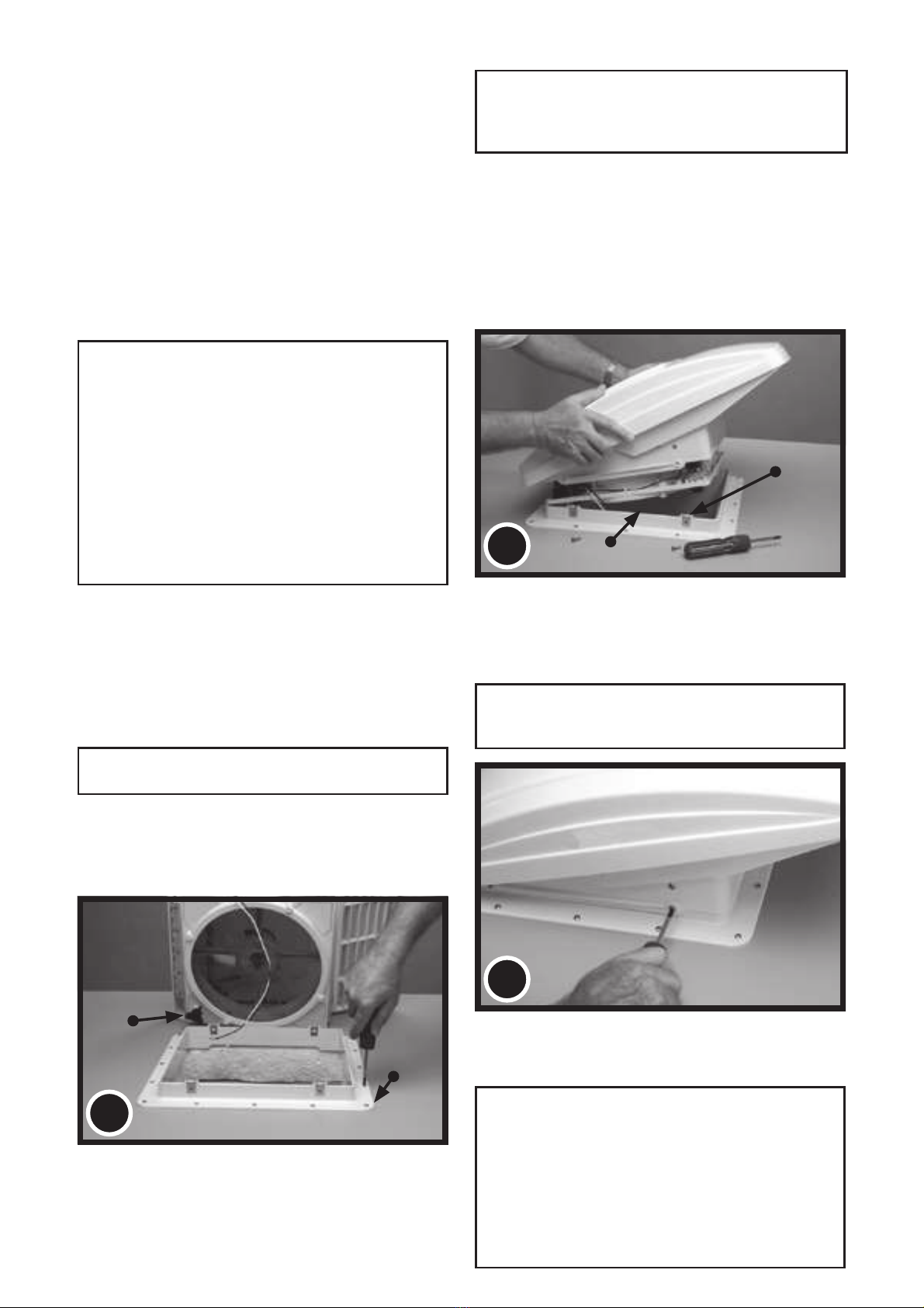
ÉTAPE 4
Assurez-vous que les 4 attaches métalliques de montage
sont solidement placées sur la Roof Receiving Flange
(Bride de réception du toit). Ouvrez le MAXXFAN et placez
l’échappement/prise d’air face à l’arrière du véhicule, faites
descendre le MAXXFAN sur la Bride de réception du toit.
Assurez-vous que les câbles d’alimentation glissent vers
l’intérieur du véhicule et ne s’entremêlent pas sur l’extrémité
supérieure de la Bride de réception du toit.
ÉTAPE 5
Assurez-vous que le MAXXFAN est complètement posé
sur la Bride de réception du toit puis serrez-le à la Bride de
réception du toit à l’aide des quatre vis en acier inoxydable
de 19 mm Nº 10 fournies.
ATTENTION : Utilisez uniquement les vis fournies/
exigées pour cette installation au risque de causer des
dommages internes et/ou de faire un mauvais montage.
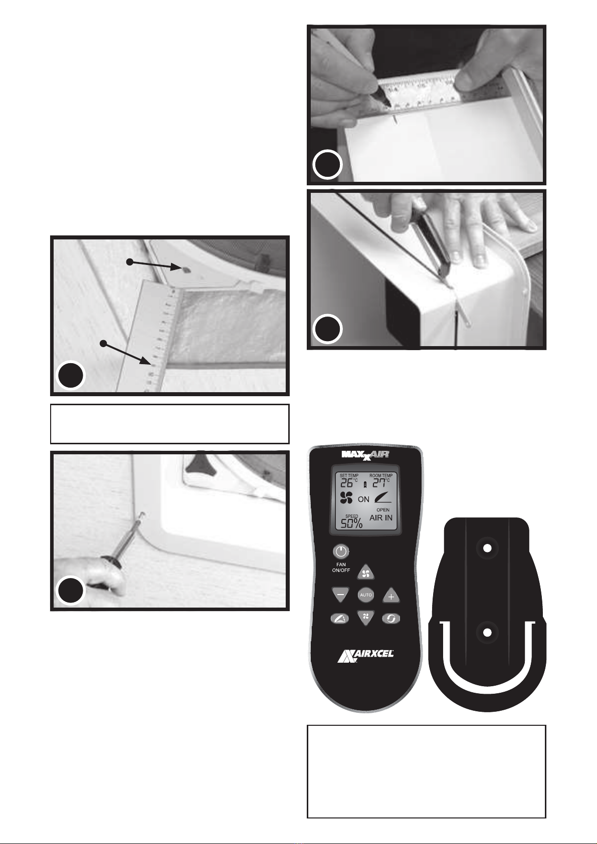
ÉTAPE 1
MAXXFAN a besoin d’une ouverture de 355 mm x 355 mm
sur le plafond pour les modèles KI et de 400 mm x 400 mm
SRXUOHVPRGqOHV.,6LYRXVUHPSODFH]XQDXWUHW\SHGpMj
installé, déposez l’ancien évent de toiture qui s’y trouve.
Retirez tous les anciens produits d’étanchéité sur au moins
50 mm autour de l’ouverture du toit.
Placez la cadre de toit MAXXFAN (voir photo Nº 2 ci-dessous)
dans l’ouverture du toit et tracez une ligne à l’aide d’un crayon
DXWRXU G¶HOOH SRXU PDUTXHU OD VXUIDFH SURSUH GX MRLQW TXL
sera utilisé. Notez que la cadre de toit doit être centrée dans
l’ouverture du toit avec les attaches métalliques faisant face
aux côtés du véhicule (ne doivent pas être face à l’avant ou à
l’arrière du véhicule).
ATTENTION : Pendant l’installation de la cadre de toit,
utilisez uniquement un produit de calfeutrage/d’étanchéité
compatible avec la bride (produit en plastique) et la surface
du toit. N’UTILISEZ PAS de matières contenant des
solvants à l’instar du, ou similaires au xylène, au toluène,
au méthyléthylcétone, à l’acétate ou acétone puisqu’elles
peuvent endommager la bride. Il faut aussi éviter les produits
d’étanchéité de type polysulfure (thiokol). Les produits
d’étanchéité à base de silicone tel que G.E. Silicone II (ne
peuvent être peints) utilisés pour les extérieurs se sont
avérés convenables pour cette installation.
En cas de doute, contactez le fabricant de votre caravane
pour plus d’informations.
ÉTAPE 2
Appliquez le produit d’étanchéité ou de calfeutrage dans la
zone que vous avez délimitée sur le toit à l’aide d’un crayon.
Appliquez-le avec soin pour éviter de créer des espaces
pouvant permettre à l’eau de s’incruster.
Serrez la Bride de réception du toit sur le toit avec les vis
SUpYXHVjFHWHႇHW
Appliquez une couche supplémentaire du produit d’étanchéité du
toit sur la tête de la vis et autour de l’extrémité de la cadre de toit.
ATTENTION : Débranchez le câble d’alimentation
du véhicule principal avant de brancher l’alimentation à
12 volts CC au MAXXFAN!
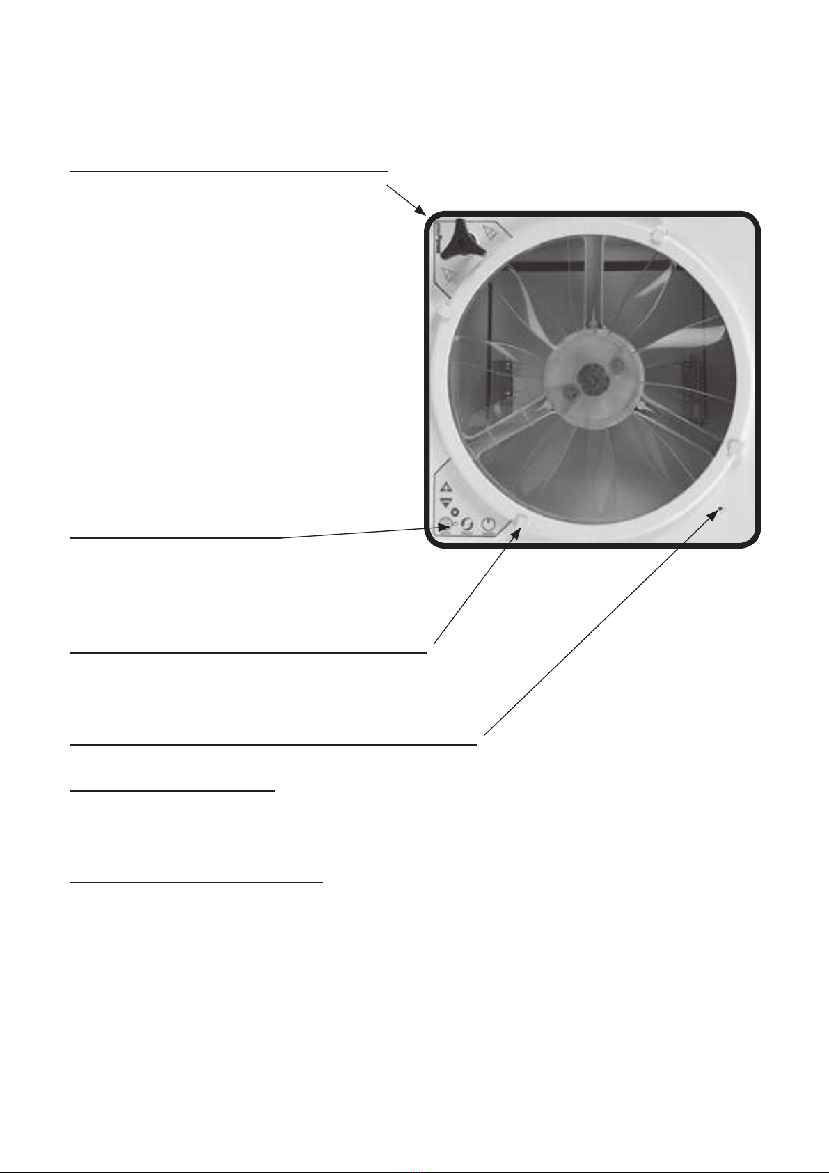
REMARQUE : Le MAXXFAN doit être entièrement ouvert
avant de passer à l’ÉTAPE 3. Tournez le bouton pour
soulever entièrement le couvercle de l’évent.
REMARQUE : Pour les modèles sans télécommande (NON-
REMOTE) tirer sur le bouton pour le déverrouiller avant de
tourner
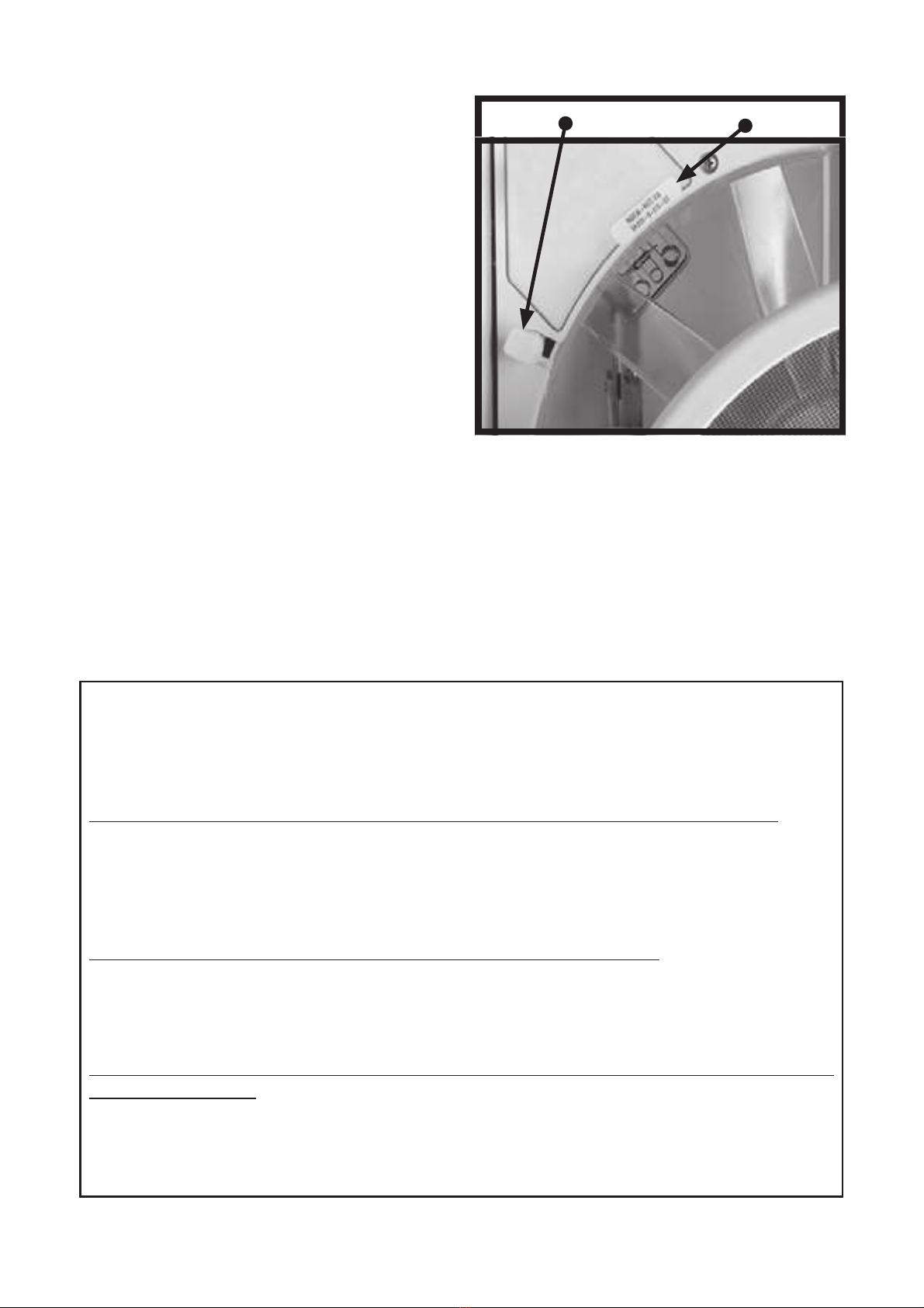
ÉTAPE 3
A l’aide des connecteurs électriques isolés fournis, branchez
l’alimentation à 12 volts du véhicule aux deux câbles
d’alimentation MAXXFANTXLVHWURXYHQWGXF{WpFKDXႇHXU
du MAXXFAN.
REMARQUE : Le câble noir MAXXFAN reconnaissable
par une étiquette marquée (+) doit être connecté à la borne
positive d’alimentation à 12 volt (+).
CECI COMPLÈTE LA PORTION SUPÉRIEURE
DU TOIT DE L’INSTALLATION
REMARQUE: Branchez à nouveau l’alimentation à 12 volts
du véhicule. Le MAXXFAN émettra un bip pour indiquer
que l’alimentation est bien branchée. Par ailleurs, le modèle
télécommandé fermera automatiquement le couvercle
d’aération. Si le MAXXFAN n’émet pas un bip lorsque
l’alimentation est branchée, retournez à l’étape Nº 3. Assurez-
YRXV TXH OHV EUDQFKHPHQWV pOHFWULTXHV RQW pWp HႇHFWXpV
et que l’alimentation à 12 volts est en marche et disponible.
Ce MAXXFAN contient un fusible à réarmement automatique
sur le circuit imprimé qui se trouve sur le plafond. Il peut être
réarmé en mettant le véhicule hors tension et en l’alimentant
à nouveau. Si votre ventilateur ne fonctionne pas ou doit
être reprogrammé, sollicitez l’assistance de votre Distributeur
AIRXCEL/MAXXAIR ou demandez l’aide d’un électricien.
BRIDE DE RÉCEPTION
EXTRÉMITÉ SUPÉRIEURE
MONTAGE MÉTALLIQUE
ATTACHES
4
OUVERTURE/
FERMETURE DU
BOUTON
BRIDE
DU TOIT
2
INSTRUCTIONS D’INSTALLATION - TOUS LES MODELES
10