manuals.online logo
Brands
  1. Home
  2. •
  3. Brands
  4. •
  5. Maxxair
  6. •
  7. Automobile Accessories
  8. •
  9. Maxxair MaxxFan User manual

Maxxair MaxxFan User manual

Step 1
Remove the old existing roof vent. Remove all old roof sealant for a minimum of 2” entirely around the
roof opening.
Place the MaxxFan Roof Receiving Flange (ref. photo #3) into the roof opening and trace a pencil line
around it to verify the clean seal area that will be required. Note that the Roof Receiving Flange must be
centered in the roof opening with the metal clips facing the sides of the vehicle (not facing the front or rear
of the vehicle).
MaxxAir – the leader in RV ventilation
From MaxxAir Vent Corporation
NOTE: Refer to supplied attachments for further instructions regarding the model you have
purchased.
The MaxxFan installs into a standard RV roof opening of 14 by 14 inches.
To determine if your roof opening is correctly sized, simply remove the interior ceiling garnish trim
ring of your existing roof vent and measure the ceiling opening or verify the opening is large enough
by sliding the MaxxFan interior Garnish trim ring into the opening.
Due to the exhaust/intake louvers that face the rear of the vehicle, the MaxxFan requires a roof
area clear of obstructions such as air conditioners, storage boxes, etc. for at least 8 inches to the
rear of the existing standard roof vent flange outer rear edge.
The MaxxFan is designed for a minimum roof thickness of 1 1/8 inches to a maximum of 6 1/2
inches. If your roof thickness is less than 1 1/8 inches, build additional thickness at the ceiling
opening using wood or other suitable material.
The MaxxFan requires a minimum 12 Volt DC, 5 amp service. Confirm that the circuit you intend to
use will accommodate the additional load. Use the proper gauge stranded wire for electrical
connections.
P/N 10-50201 - Rev. 9/13/05
Patent Pending
MaxxFanTM Installation Instructions
WARNING - To reduce risk of fire, injury to persons or damage to property, use only in the manner
intended by MaxxAir Vent Corp. If you have questions, contact MaxxAir Vent Corp. @ 1-800-780-9893
Read and Save
These Instructions
CSA approved.
Exhaust/Intake
Louvers
Step 2
Apply factory recommended roof sealant to
the area traced with the pencil. Apply roof sealant
carefully so that no gaps are present that may
allow water to enter.
Step 3
Fasten the Roof Receiving Flange to the roof
with the screws provided.
Apply additional roof sealant over the screw
heads and around the edge of the roof flange.
Caution: Disconnect main vehicle
power before connecting 12 volt DC
power to the MaxxFan!
Step 4
Using the insulated electrical connectors
provided, connect the vehicle 12 volt power to the
two MaxxFan power wires located on the driver
side of the MaxxFan.
Note: The MaxxFan black wire identified with a
tag showing (+) must be connected to the
vehicle 12 volt (+) positive supply.
Disconnect main vehicle power
again before proceeding!
Step 5
Confirm that the 4 metal mounting clips are
firmly in place on the Roof Receiving Flange.
With the MaxxFan open and the exhaust/intake
louvers facing the rear of the vehicle, lower the
MaxxFan onto the Roof Receiving Flange.
Make sure the power wires slide to the vehicle
interior and do not become entangled on the
Roof Receiving Flange upward edge.
Step 6
Verify the MaxxFan is fully seated down on the
Roof Receiving Flange and fasten the MaxxFan
to the Roof Receiving Flange using the four 3/4
inch long by #10 Stainless Steel screws pro-
vided. (Caution: Only use screws provided/
specified for this installation)
This completes the roof top portion of
the installation.
NOTE: After making the 12 volt DC power
connections you may re-apply vehicle power
and temporarily operate the MaxxFan to
verify proper wire connections. Please note
that the MaxxFan motor only operates when
the MaxxFan is fully opened. Use the Vent
Open Knob, pull down and outward to
unlock and fully raise the MaxxFan vent lid.
(See attached operating instructions.)
Verify that the fan operates in exhaust
when the exhaust switch is selected, if not,
reverse the 12 volt DC power leads to the
MaxxFan and verify correct operation.
3
6
5
Roof Flange
Metal
Mounting
Clips
Step 7
The interior Garnish Trim Ring must be
trimmed to fit your particular RV roof thickness.
To accomplish this, measure the distance from
the vehicle ceiling surface to each corner of the
MaxxFan Control Plate.
Most RV roofs have some slope, so measuring
each corner is necessary. The Garnish ring
should be cut 1/4 to 1/2 inch longer than the
dimensions measured at each corner.
7
7A - After adding 1/2 inch more, a line is drawn
on the outside of the Garnish Ring at 4 inches.
7B - Connect all four corners with a line at the
required dimension and trim accordingly.
Step 8
Complete the installation by placing any excess
wiring to the inside of the roof opening and sliding
the Garnish Ring into position. Fasten in place
using the four painted flat head screws provided.
For additional information about your
MaxxFan, please read the enclosed
“Information and Operating Guide”.
AB
Congratulations!
You have successfully
completed the installation
of your new MaxxFan.
If there is anything we can
do for you, please visit
our website www.maxxair.com
or call us at:
(800) 780-9893
8
In the picture shown to the left (#7), the installation,
(example only), measures 3 and 1/2 inches from
the ceiling to the Control Plate. Go to 7A & 7B.
Ceiling
Control
Plate
Garnish
Ring
(Measurements are an example for illustration purposes only.)
Visit our website at www.maxxair.com
MaxxAir Vent Corp •5513 W. Sligh Ave •Tampa, FL 33634 •Phone (800) 780-9893 •(813) 882-8282 •Fax (813) 876-2550
MaxxAir Vent Corp. warrants this product to be free of manufacturing defects, regardless of ownership for a period
of two years from the original date of purchase. You must keep your original sales receipt. This Limited Warranty
does not include failure due to accidents, “Acts of God”, misuse, improper installation or incidental damages. During
the two year warranty period, if your MaxxFan fails to operate properly under normal conditions, please call MaxxAir
toll free at 1-800-780-9893 for assistance. Please have your original sales receipt and MaxxFan Serial Number
readily available when you call. The serial number shown on this card is also located on the outer right side of your
Control Box, on the interior wall of the fan duct (viewed through roof vent opening from inside your vehicle) and below
the rectangular exterior screen on the MaxxFan Housing (located on the roof). MaxxAir will correct a confirmed defect
within 45 days by repair or replacement without charge for materials or labor. This warranty does not cover any freight
costs for the return of the product to or from MaxxAir Vent Corp., or costs
associated with installation, removal or reinstallation of the product. Your
MaxxFan is CSA Certified and conforms to UL507.
We invite your comments and suggestions regarding our products. Any
information you supply is for MaxxAir’s internal use and will not be shared
or sold to others.
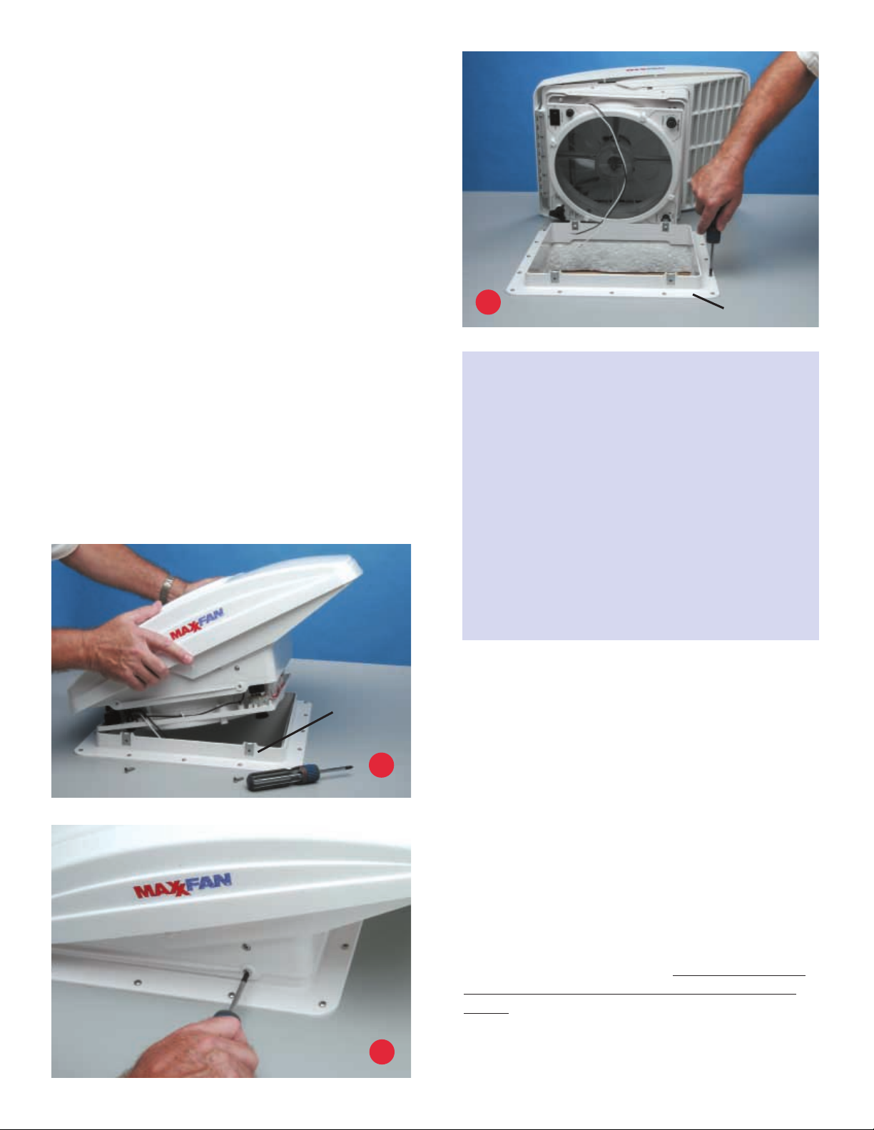
The Serial number for your MaxxFan is located on the fan control plate
under the round insect screen frame. Reference your operating guide.
Rotate the four retaining knobs 180oand remove the screen to view. Do
not operate the MaxxFan with the screen removed
MaxxFanTM Two Year Limited Warranty
CAUTIONS AND CARE OF THE MaxxFan
This product has been manufactured using prime UV stabilized Polymers for maximum
toughness and durability. However, the use of non-compatible chemicals will cause cracking
and product failure.
Please clean all parts with mild soap and water only.
Do not use Petroleum Containing Additives or Solvent Based Products on any of the
MaxxFan’s components or its corrosion resistant hardware.
Listed below are some known chemical products to be aware of:
NON COMPATIBLE CHEMICALS - DO NOT USE THESE
Keytones, Esters, Acetone or other like solvents, Halogenated Hydrocarbons, Amines,
Aromatic Hydrocarbons, (Loctite Formulas), or references re: chemicals that are not to be
used on Plastics.
GENERALLY COMPATIBLE (But should be used in low concentration where possible)
Acids, Alcohol, Alkalis, Aliphatic Hydrocarbons, Mild Soap solution (avoid strong Alkaline
material), Silicone Oil or Greases (avoid those containing Aromatic Hydrocarbons or other
additives). Review the contents of your cleaning materials carefully.
Serial Number

Other Maxxair Automobile Accessories manuals

Maxxair SKYMAXX 97500i User manual

Maxxair

Maxxair SKYMAXX 97500i User manual

Maxxair SKYMAXX LX 97000i Manual

Maxxair

Maxxair SKYMAXX LX 97000i Manual

Maxxair MAXXFAN Deluxe Series User manual

Maxxair

Maxxair MAXXFAN Deluxe Series User manual

Maxxair UNIMAXX User manual

Maxxair

Maxxair UNIMAXX User manual

Popular Automobile Accessories manuals by other brands

Menabo DELTA DL FIX 201FP Fitting instructions

Menabo

Menabo DELTA DL FIX 201FP Fitting instructions

eRapta AYX103 Installation and operation guide

eRapta

eRapta AYX103 Installation and operation guide

Safe Fleet Prime Design PCR-0005 Assembly instructions

Safe Fleet

Safe Fleet Prime Design PCR-0005 Assembly instructions

JMD Handy-Baby user manual

JMD

JMD Handy-Baby user manual

Lanner LVC-2001 user manual

Lanner

Lanner LVC-2001 user manual

MayPole MP9529 user guide

MayPole

MayPole MP9529 user guide

Safe Fleet PRIME DESIGN FBM-1029-BLK manual

Safe Fleet

Safe Fleet PRIME DESIGN FBM-1029-BLK manual

Kolpin 25-9250 Owner's and operator's manual

Kolpin

Kolpin 25-9250 Owner's and operator's manual

Lund Interceptor Installation instruction

Lund

Lund Interceptor Installation instruction

Directed Directechs DB3 installation guide

Directed

Directed Directechs DB3 installation guide

Hella 2PT 980 680-101 Mounting instructions

Hella

Hella 2PT 980 680-101 Mounting instructions

Warn 70045 installation instructions

Warn

Warn 70045 installation instructions

Team Tech Offroad TACOMA HOOD STRUT Kit Installation

Team Tech Offroad

Team Tech Offroad TACOMA HOOD STRUT Kit Installation

SportRack A30404TW200 manual

SportRack

SportRack A30404TW200 manual

SCHROTH Interior Net Installation and use guideline

SCHROTH

SCHROTH Interior Net Installation and use guideline

AA Products RB0006 instruction manual

AA Products

AA Products RB0006 instruction manual

Cruz Evo Rack Module E23 Assembly instructions

Cruz

Cruz Evo Rack Module E23 Assembly instructions

CAR-connect VAS 671 001 operating manual

CAR-connect

CAR-connect VAS 671 001 operating manual

manuals.online logo
manuals.online logoBrands
  • About & Mission
  • Contact us
  • Privacy Policy
  • Terms and Conditions

Copyright 2025 Manuals.Online. All Rights Reserved.