[email protected] 866-MAXXIMA
(629-9462)
www.maxxima.com
125
Cabot
Court
Hauppauge,
NY
11788
Page 4 of 4 Page 1 of 4
[email protected] 866-MAXXIMA
(629-9462)
www.maxxima.com
125
Cabot
Court
Hauppauge,
NY
11788
CAUTION
• Prior to drilling holes into the vehicle for installation, ascertain that no internal
components of the vehicle will obstruct the placement or mounting of the LED minibar.
For all wire passage holes, apply caulk or install grommets.
• Avoid installing the minibar or routing any cables in the vicinity of the vehicle's airbags.
Any interference could hinder the proper deployment of the airbags, thereby
compromising their intended effectiveness.
• Carefully select the mounting location for the minibar, avoiding areas that may impair
visibility or distract the vehicle's operator. Improper placement could obstruct the
operator's view or divert their attention, potentially leading to serious accidents.
• For cleaning the outer lens of the minibar, only use a mixture of soap and water.
Utilizing other chemicals may lead to premature cracking or discoloration of the lens.
Damaged lenses can significantly impede the minibar's functionality.
Regularly inspect and operate the minibar to ensure it is working optimally.
• Refrain from looking directly into the minibar while it is operational. The high-intensity
LEDs used in this device can cause temporary blindness or even permanent eye damage.
WIRING/ELECTRICAL
Operation using the cigarette plug (M20487):
• Connect the minibar cigarette adapter to the cigarette lighter outlet.
• Press the first switch to power the lightbar. The red LED should illuminate.
• Cycle through the patterns by pressing the other switch for 1 second at a time.
• Revert to pattern 1 by pressing the pattern selector for 5 seconds.
NOTE: When the lightbar is turned off and powered on again, the previously set lightbar
pattern will illuminate on the lightbar.
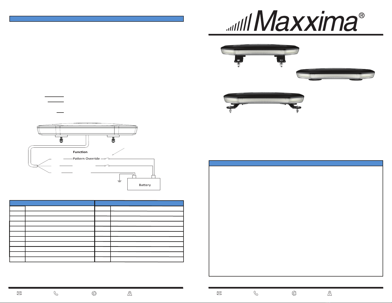
Operation without using the cigarette plug (M20488):
BLACK - Ground ------------------
RED - Main Power ----------------
YELLOW - Trigger Wire ---------
Extend to the vehicle ground.
Extend to a switch and then to the POSITIVE battery
terminal. Fuse appropriately.
To cycle to the next pattern, tap to +VDC for 1 second.
Yellow
Red
Black
Wire color
Wiring Diagram
12/24VDC (+)
Ground (-)
(-) (+)
FLASH PATTERNS
Pattern
1
2
3
4
5
6
7
8
9
10
Flash Pattern Description
Single [125FPM] (Class 1)
Single [75FPM] (CA13, Class 1)
Double (Class 1)
Triple
Clockwise Rotation
Symmetrical Rotation
Counterclockwise Rotation
Pattern7 x 4cycle + 3 Single Flash
Single (Split Left & Right) Split
Triple (Middle + Two Ends + Full)
LED MINIBAR INSTRUCTION MANUAL
M20487/M20488
FLASH PATTERNS
Pattern
11
12
13
14
15
16
17
18
Flash Pattern Description
Go and Back “C” shape running
Progressive (Left + Right)
Quad (Left & Right) Split
Double (Left & Right) Split
Quint (Left & Right) Split
Strobe (Left & Right) Split
Fast & Slow Double (Left & Right) Split
Fast & Slow Quad (Left& Right) Split
Momentary switch (optional)


