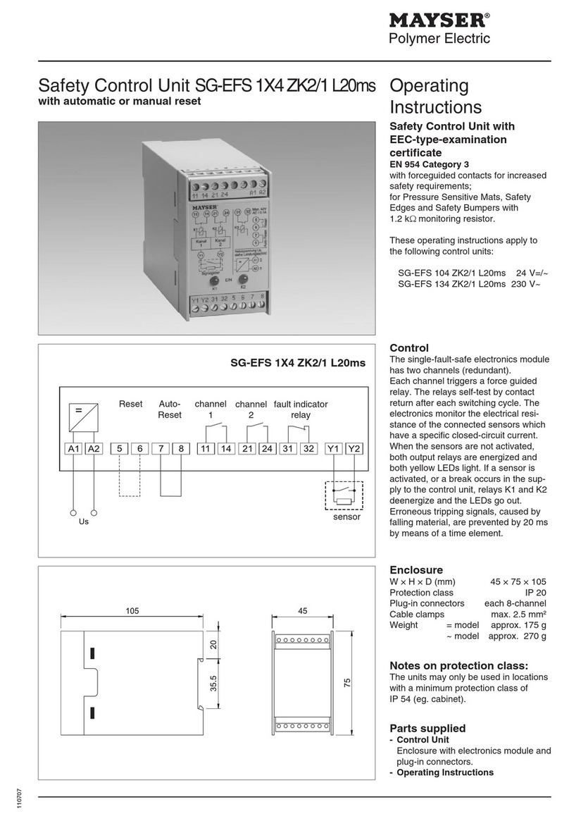
MAYSER SG-EFS User manual

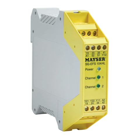
Control unit SG-EFS 104/4L
Original instructions
1004128 SG-EFS 104/4L AC/DC 24V
Mayser GmbH & Co. KG
Örlinger Straße 1–3
89073 Ulm
GERMANY
Tel.: +49 731 2061-0
Fax: +49 731 2061-222
E-mail: info.ulm@mayser.com
Website: www.mayser.com
Innovative by tradition.
EN | Operating instructions Version 2

Page 2/17 Operating Instructions SG-EFS 104/4L 011221 v3.11-RiA
The Declaration of Conformity is available in the Downloads section of our website:
www.mayser.com.
Safety first!
•Read the instructions carefully before use.
•The warnings in the instructions are there to warn you of any unexpect-
ed dangers. Always heed the warnings.
•Keep the instructions somewhere safe so you can refer to them
throughout the product’s entire service life.
•Pass the instructions on to every subsequent owner or user of the prod-
uct.
•Add any supplement received from the manufacturer to the instruc-
tions.
•Observe the information under “Safety” (starting on page5).
Conformity
The design type of the product complies with the basic requirements of the following
directives:
•2014/30/EU (EMC)
•2011/65/EU (RoHS)
EC type examination
The product has been tested by an independent institute.
There is an EC type examination certificate to confirm conformity.
The EC type examination certificate is stored in the Downloads section of our web-
site: www.mayser.com.
UL certification
The design type of the product conforms to the basic requirements of UL certifica-
tion:
•UL508

011221 v3.11-RiA Operating Instructions SG-EFS 104/4L Page 3/17
Table of contents
About these instructions......................................................................................................................................................4
Safety..........................................................................................................................................................................................5
Intended use .........................................................................................................................................................................5
Safety instructions................................................................................................................................................................5
Residual dangers ..................................................................................................................................................................6
Parts supplied ..........................................................................................................................................................................6
Storage ......................................................................................................................................................................................7
Product overview....................................................................................................................................................................7
Connections...........................................................................................................................................................................7
LEDs information..................................................................................................................................................................7
Function ....................................................................................................................................................................................8
Reset........................................................................................................................................................................................8
Automatic reset........................................................................................................................................................8
Manual reset .............................................................................................................................................................8
Installation................................................................................................................................................................................8
Reset..................................................................................................................................................................................... 10
Automatic reset..................................................................................................................................................... 10
Reset via machine controls................................................................................................................................. 10
Manual reset ..........................................................................................................................................................11
Connection examples ......................................................................................................................................................11
Commissioning......................................................................................................................................................................12
Function test: automatic reset........................................................................................................................... 12
Function test: manual reset................................................................................................................................ 13
Decommissioning .............................................................................................................................................................13
Recommissioning.............................................................................................................................................................. 13
Maintenance and cleaning................................................................................................................................................14
Maintenance ......................................................................................................................................................................14
Cleaning ..............................................................................................................................................................................14
Troubleshooting and remedies ........................................................................................................................................14
Replacement parts ...............................................................................................................................................................15
Disposal ...................................................................................................................................................................................15
Technical data........................................................................................................................................................................16
Table of contents
Page 4/17 Operating Instructions SG-EFS 104/4L 011221 v3.11-RiA
About these instructions
Symbols used Symbol Meaning
Ä... Action with one step or with more than one step where
the order is not relevant.
1. ... Action with more than one step where the order is rel-
evant.
• ...
- ...
Bullets first level
Bullets second level
(see Installation) Cross-reference
Danger symbols and
information
Symbol Meaning
DANGER Immediate danger leading to death or serious injury.
WARNING Imminent danger which may lead to death or serious injury.
CAUTION Possible danger which may lead to minor or moderate inju-
ries.
NOTE Potential risk of damage to property or the environment.
Information on easier and safer working practices.
Other applicable
documents
ÄPlease also observe the following documents:
-Drawing of the sensor system (optional)
-Wiring diagram (optional)
-Installation instructions for the sensors used
Target group These instructions are intended for the operating company and for electrically skilled
persons. The electrically skilled person must be familiar with installation and commis-
sioning.
Validity These instructions are only valid for the products specified on the title page.
These instructions are part of the product.
Mayser accepts no responsibility or warranty claims for damage and consequential
damage due to failure to observe the instructions.
About these instructions
Measurements
used in drawings
Unless stated otherwise, all measurements are in millimetres (mm).

011221 v3.11-RiA Operating Instructions SG-EFS 104/4L Page 5/17
Safety
Intended use
ÄDo not open the control unit
Never open, tamper with or attempt to modify the control unit.
ÄObserve protection class
Only use the control unit in spaces with a minimum protection class of IP54 (e.g.
a switch cabinet).
The control unit is designed for processing the signals of a pressure-sensitive protec-
tive device (PSPD). It evaluates the output signals of BK-type sensors. The integrated
output signal switching devices (OSSD) transmit the evaluated safety signals directly
to the downstream control.
The product complies with ISO13849-1:2015 category3 PLe. To prevent any reduc-
tion in the safety classification, the downstream control must be of the same catego-
ry or higher.
Safety
Safety instructions
To prevent irreparable damage to the product, you must observe the following safe-
ty instructions.
ÄDo not use in ATEX zones
Do not use the control unit in potentially explosive environments (ATEX). The
control unit is not authorised for use in these zones.
ÄIn the event of a fault, put out of operation
In the event of malfunctions and visible damage, put the control unit out of oper-
ation by decommissioning it.
ÄPrevent the machine from restarting
Prevent the machine from restarting while a hazard exists, e.g. by using a starting
lockout.
ÄAvoid electric shocks
To avoid electrical injuries when working on electrical systems, disconnect them
from the power supply and secure them to prevent them being switched back
on.
For your own safety, you must adhere to the following safety instructions.
ÄTake care when setting up the interface
Overall safety is aected by the quality and reliability of the interface between
the protective device and the machine. Take particular care when setting up the
interface.

Page 6/17 Operating Instructions SG-EFS 104/4L 011221 v3.11-RiA
Terminals Y11, Y12 and Y21, Y22 are not voltage-free.
Parts supplied
Parts supplied
1× Control unit
Enclosure with electronics module and plug-in connectors.
1× Operating Instructions
1× Declaration of Conformity
ÄUpon receipt, immediately check the parts supplied to ensure they are complete
and in good condition.
ÄContinue redundancy
Make sure you wire the unit directly in the control circuit or that two channels
continue to be used in the downstream control.
Residual dangers
There are no known residual dangers associated with this product.
ÄDo not interconnect control units
Do not combine control units by interconnecting them.
ÄFit spark absorbers
When connecting inductive loads, fit spark absorbers (RC circuits) to the consum-
er.
ÄCheck supply voltage
Check the supply voltage. It must correspond to the connecting voltage USspeci-
fied on the type plate.
ÄObserve correct terminal assignment
Observe the correct terminal assignment when connecting the supply voltage.
ÄProtect relay contacts
Risk of contact welding: provide the relay contacts with external fuse protection.
ÄDo not overload control unit
Ensure that the specified switching current is not exceeded.
ÄDo not exceed maximum number of sensors
Do not connect more sensors to the control unit than the maximum number
specified in the sensor installation instructions.
ÄEnsure sucient clearance
When installing the product in a switch cabinet, ensure sucient clearance from
heat sources (at least 2cm).

011221 v3.11-RiA Operating Instructions SG-EFS 104/4L Page 7/17
•Light-green “Power” LED:
supply voltage connected
•Green “Channel 1” LED:
relay K1 picked up
•Green “Channel 2” LED:
relay K2 picked up
Connections: Terminals:
Supply voltage A1, A2
BK-type sensor Y11, Y12
Y21, Y22
OSSD 1 13, 14
OSSD 2 23, 24
OSSD 3 33, 34
Signal output 41, 42
Bridge for automatic reset S1, S2
Manual reset button
Storage
Product overview
Connections
LEDs information
ÄStore control units in the original packaging and in a dry place.
ÄObserve the storage temperature in accordance with the technical data.
Storage

Page 8/17 Operating Instructions SG-EFS 104/4L 011221 v3.11-RiA
The single-fault-safe electronics module has two channels (redundant). Each channel
controls a force-guided relay and additionally monitors the relay of the other channel.
The relays control OSSD 1 (terminals 13, 14), OSSD 2 (terminals 23, 24) and OSSD 3
(terminals 33, 34). The electronic system monitors the connected BK-type sensors.
The control unit is operated with a voltage of AC/DC 24 V. When the supply voltage
is connected, the light-green “Power” LED is lit.
When the sensor is not activated, and after a reset, OSSDs 1, 2 and 3 are closed and
the signal output is open. The green “Channel1” and “Channel2” LEDs are lit.
If the sensor is activated or the sensor cable breaks, OSSDs 1, 2 and 3 are open and
the signal output is closed. The green “Channel1” and “Channel2” LEDs go out.
The signal output works the opposite way round to the OSSDs.
Function
Function
Installation
1. Fix the control unit in any position on a 35°mm mounting rail acc. to IEC60715.
For your own safety, you must also adhere to the following rules during installation:
•Disconnect from the power supply all devices and live parts that are located in
the immediate vicinity.
•Secure them to prevent them being switched back on.
•Check that they are de-energised.
Reset
Automatic reset
The control unit works without a reset function. If the protective device stops being
actuated, the output signal switching device of the control unit automatically switch-
es from the OFF state to the ON state after a delaytw. Without an additional starting
lockout, the machine would start up again immediately.
If the reset button is pressed, the OSSDs return to HIGH after a delaytw.
Manual reset
The control unit works with a reset function. If the protective device stops being actu-
ated, the output signal switching devices of the control unit remain in the OFF state.
This prevents the machine from restarting. Only a “Reset” command will change the
state from OFF to ON.

011221 v3.11-RiA Operating Instructions SG-EFS 104/4L Page 9/17
ÄTighten the screws of the cable terminals to a torque of between 0.5 and 0.6Nm.
(UL: overtorquing may cause enclosure breakage.)
(UL: use 60/75°C copper wire only)
Installation
Caution Impaired operation due to overheating
If the control unit overheats as a result of external heat, operation of the protec-
tive device may be impaired or it may fail completely.
ÄIt is absolutely essential to ensure sucient clearance from heat sources (at
least 2cm).
Sensor
2. Wire the sensors, OSSDs and supply voltage to the cable terminals.

Page 10/17 Operating Instructions SG-EFS 104/4L 011221 v3.11-RiA
Sensor 1 Sensor 2
Cable Sensor Y11 Y21 Y22 Y12
2× 2-core SL BN WH WH BN
2× 2-core SM, TS, SL, SP, SB BK RD RD BK
2× 2-core SM11 BN BU BU BN
1× 4-core SM, SB BK BU WH BN
Colour coding:
BK Black
BU Blue
BN Brown
RD Red
WH White
The two contact surfaces of the sensor act as bridges between connections Y11 and
Y12 and connections Y21 and Y22 respectively. This is the only way to ensure proper
monitoring of the sensor and detection of a cable break.
ÄPay careful attention to paths that are supposed to have single-colour wiring
from end to end, e.g. red wires at both Y21 and Y22.
ÄAlways connect multiple sensors in series:
Reset via machine controls
In order for a manual reset to be performed via the machine controls (with the reset
function), a NO contact of the controls must be connected.
ÄConnect the wiring for the NO contact of the machine controls between cable
terminals S1 and S2.
Installation
Automatic reset
ÄInsert a bridge between cable terminals S1 and S2.
A bridge must be inserted to trigger an automatic reset (without the reset function).
Reset

011221 v3.11-RiA Operating Instructions SG-EFS 104/4L Page 11/17
Q1
Q1 Q2
Q2
M
Q2
Q3
M
Q2
SG-EFS 104/4L
F2
13
14
23
24
Q1
OSSD 1
OSSD 2
OSSD 3
Q1
F3
Q2
Q3
33
34
Q2
F4
Q3
Integrate the circuits for enabling the machine
ÄConnect the NC contacts of the external contactors to the reset button at cable
terminals S1 and S2, ensuring they are connected in series (see Connection exam-
ples).
Machine controls
Installation
Manual reset
In order for a manual reset to be performed (with the reset function) a button must
be connected.
ÄWire up a button between cable terminals S1 and S2.
Connection examples
Connection example 1
Caution Automatic reset due to jammed/sticking reset button
If the protective device stops being actuated, the OSSDs automatically switch
from the OFF state to the ON state. Risk of injury or property damage due to un-
expected restart.
ÄIt is essential to use a high-quality button.
ÄTest the function of the button regularly (at least once a month).
Connection example 2

Page 12/17 Operating Instructions SG-EFS 104/4L 011221 v3.11-RiA
3. Disconnect the sensor.
-The green “Channel1” and “Channel2” LEDs go out
-OSSDs 1, 2 and 3 are open
-The signal output is closed
1. Make sure no sensors are activated.
-The green “Power”, “Channel 1” and “Channel 2” LEDs are lit
-OSSDs 1, 2 and 3 are closed
-The signal output is open
2. Activate the sensor.
-The green “Channel1” and “Channel2” LEDs go out
-OSSDs 1, 2 and 3 are open
-The signal output is closed
Commissioning
Commissioning
ÄConnect the supply voltage.
Function test: automatic reset
WARNING Danger of injury from electric shock
ÄNever unplug plug-in connectors while live.
with manual reset
Contact duplication
with automatic reset

011221 v3.11-RiA Operating Instructions SG-EFS 104/4L Page 13/17
1. Make sure no sensors are activated.
-The green “Power” LED is lit
-OSSDs 1, 2 and 3 are open
-The signal output is closed
2. Activate the reset button.
-The green “Power”, “Channel 1” and “Channel 2” LEDs are lit
-OSSDs 1, 2 and 3 are closed
-The signal output is open
3. Activate the sensor.
-The green “Channel1” and “Channel2” LEDs go out
-OSSDs 1, 2 and 3 are open
-The signal output is closed
4. Repeat step 2.
5. Disconnect the sensor.
-The green “Channel1” and “Channel2” LEDs go out
-OSSDs 1, 2 and 3 are open
-The signal output is closed
Commissioning
Function test: manual reset
Recommissioning
ÄCarry out the commissioning process (see Commissioning).
Decommissioning
ÄDisconnect the protective device and secure it to prevent unintentional recon-
nection.
ÄAttach a clear notice to the protective device stating that it is temporarily or per-
manently out of service.

Page 14/17 Operating Instructions SG-EFS 104/4L 011221 v3.11-RiA
Fault indication Possible cause Remedy
Light-green “POWER” LED
not lit
No or incorrect supply voltage 1. Check supply voltage, compare with
type plate
2. Check terminal assignment
If supply voltage is correctly connected:
control unit is faulty
ÄReplace control unit
The green “Channel 1”
and “Channel 2” LEDs are
not lit
Manual reset: reset button not activated ÄActivate reset button
Manual reset: connection to button inter-
rupted
ÄCheck connection to button
Manual reset: button jammed/sticking ÄReplace buttons on S1 and S2
Automatic reset: bridge missing ÄConnect bridge between S1 and S2
Sensor faulty or connection to sensor inter-
rupted
1. Disconnect sensor
2. Bridge connections Y11, Y12 and Y21,
Y22
3. Activate reset button
4. If LEDs are lit: replace sensor
Control unit faulty ÄReplace control unit
Only one green channel
LED is lit:“Channel 1” or
“Channel 2”
Incorrect supply voltage ÄCheck supply voltage, compare with
type plate
Control unit faulty ÄReplace control unit
Maintenance and cleaning
Cleaning
ÄClean the outside of the enclosure with a dry cloth.
Maintenance and cleaning
Maintenance
The control unit is maintenance-free.
ÄRepeat the function test monthly.
Troubleshooting and remedies
Prerequisites:
•The signal system has passed the latest test (see sensor installation instructions).
•The control unit is connected to the supply voltage and sensor.
•No sensor is activated.

011221 v3.11-RiA Operating Instructions SG-EFS 104/4L Page 15/17
Replacement parts
Still unable to resolve the fault?
ÄContact Mayser-Support: Tel. +49 731 2061-0.
ÄIn the event of enquiries, have the information from the type plate to hand.
Type plate There is a type plate on the side of the control unit for identification purposes.
Replacement parts
CAUTION Overall safety at risk
Failure to use original Mayser parts when replacing parts of the product can im-
pair the function of the protective device.
ÄOnly use original Mayser parts.
Disposal
The control units produced by Mayser are professional electronic tools exclusively in-
tended for commercial use (known as B2B devices). Unlike the B2C (business-to-con-
sumer)devices mainly used in private households, they must not be disposed of at
the collection centres of public waste management organisations (e.g. municipal
recycling depots). At the end of their useful life, the devices may be returned to us for
disposal.
WEEE reg. no. DE 39141253
Control unit
Packaging •Wood, cardboard, plastics
ÄWhen disposing of the product:
-Ensure compliance with the relevant national disposal regulations and statu-
tory requirements.
-Ensure that any disposal company you use receives a list of the aforemen-
tioned materials along with the product.
-Ensure that the materials are recycled or disposed of in an environmentally
friendly way.

Page 16/17 Operating Instructions SG-EFS 104/4L 011221 v3.11-RiA
SG-EFS 104/4L AC 24 V DC 24 V
Testing basis EN12978, ISO13849-1, ISO13856-1, ISO13856-2, ISO13856-3
Connecting voltage US
Nominal voltage AC 24V DC 24V
Voltage tolerance -10% to +10% -10% to +10%
Rated current 280mA 86mA
Nominal frequency 50 to 60Hz –
External fuse protection – –
Power consumption < 7VA < 3W
Times
Reaction time ta< 50ms < 30ms
Restart time tw< 500ms < 500ms
Safety classifications
ISO13856: reset function With/without With/without
ISO13849-1:2015 Category 3 PL e Category 3 PL e
MTTFD100a 100a
DCavg 90% 90%
B10D (load: DC 24V / 2A) 4× 1054× 105
nop (assumption) 52560/a 52560/a
CCF Requirements met Requirements met
IEC 60664-1: creep distance and
air gap
Soiling degree 2, overvoltage
category III / 250V, basic insulation
Soiling degree 2, overvoltage
category III / 250V, basic insulation
Inputs
Sensor Y11, Y12 and Y21, Y22 Y11, Y12 and Y21, Y22
Short-circuit resistance ≤ 400ohms ≤ 400ohms
Line resistance ≤ 10ohms ≤ 10ohms
Line length (max.) 100m 100m
Switching thresholds
Sensor activated < 1k3ohms < 1k3ohms
Cable break – –
Outputs
OSSDs 1, 2 and 3 (NO contact) 13, 14 and 23, 24 and 33, 34 13, 14 and 23, 24 and 33, 34
Signal output (NC contact) 41, 42 41, 42
EN60947-5-1: utilisation
category
AC-12: 250V / 5A
DC-12: 30V / 5A
AC-12: 250V / 5A
DC-12: 30V / 5A
Switching voltage (max.) AC 230V DC 24V AC 230V DC 24V
Switching current (max.) 5A 5A 5A 5A
Total current (max.) 13.8A 13.8A 13.8A 13.8A
Switching capacity (max.) 1150VA 120W 1150VA 120W
Switching operations, mechanical > 1× 10⁷> 1× 10⁷
Switching operations, electrical > 1× 10⁵(DC 24V / 2A) > 1× 10⁵(DC 24V / 2A)
External fuse protection
for contacts
NO contact 6.3A quick-acting 6.3A quick-acting
NC contact 4A Neozed gL/gG 4A Neozed gL/gG
Technical data
Technical data

011221 v3.11-RiA Operating Instructions SG-EFS 104/4L Page 17/17
SG-EFS 104/4L AC 24 V DC 24 V
Mechanical operating conditions
Cable terminals 4× 4-pin 4× 4-pin
Solid wire 1× 2.5mm2or 2× 1.5mm21× 2.5mm2or 2× 1.5mm2
Strand with sheath 1× 2.5mm2or 2× 1.5mm21× 2.5mm2or 2× 1.5mm2
Tightening torque 0.5 to 0.6Nm 0.5 to 0.6Nm
IEC60529: protection class IP20 IP20
Max. humidity (23°C) 95% 95%
Operating temperature -25°C to +55°C (UL: up to +40°C) -25°C to +55°C (UL: up to +40°C)
Storage temperature -25°C to +55°C -25°C to +55°C
Impact resistance in operation 2g 2g
Dimensions (W × H × D) 22.5 × 99 × 114.5mm 22.5 × 99 × 114.5mm
Weight 180g 180g
Technical data
Table of contents
Other MAYSER Control Unit manuals

MAYSER
MAYSER SG-RSV 205 User manual

MAYSER
MAYSER SG-EFS 104/2W User manual

MAYSER
MAYSER SG-EFS 1 4 ZK2/1 L20ms Series User manual

MAYSER
MAYSER SG-EFS 104 ZK2/1 8k2 User manual

MAYSER
MAYSER SG-EFS 104/4L User manual

MAYSER
MAYSER SG-RST 204 User manual

MAYSER
MAYSER SG-RST 153 User manual

MAYSER
MAYSER SG-RS 309-2 User manual

MAYSER
MAYSER SG-RS 309-2 User manual

MAYSER
MAYSER SG-EFS 104/2W User manual