MAYSER SB/BK User manual

Safety technology
1 (12)
Assembly Manual Safety Bumper SB/BK and SB/W (NO/contact)
Rev.1 140805js
Mayser GmbH & Co. KG
Foam technology
Postfach 1362
D-88153 Lindenberg
Telephone:
Fax:
+49 (0) 83 81 / 5 07 - 0
+49 (0) 83 81 / 5 07 - 1 01
E-mail:
Internet:
bumper@mayser.de
mayser-sicherheitstechnik.de
Assembly Manual
Safety Bumper SB/BK and SB/W (NO/contact)

Safety technology
2 (12)
Assembly Manual Safety Bumper SB/BK and SB/W (NO/contact)
Rev.1 140805js
Contents
1 About this Assembly Manual .................................................................................................................. 3
2 Safety......................................................................................................................................................... 3
2.1 Intended use ...................................................................................................................................... 3
2.2 Product safety information .............................................................................................................. 4
2.3 Applied standards ............................................................................................................................. 4
3 Technical data........................................................................................................................................... 5
4 Transport and storage ............................................................................................................................. 5
4.1 Packaging and transport .................................................................................................................. 5
4.2 Storage ............................................................................................................................................... 5
5 Assembly................................................................................................................................................... 6
5.1 Prepare assembly area ..................................................................................................................... 6
5.2 Unpack ............................................................................................................................................... 6
5.3 Assembly ........................................................................................................................................... 7
5.4 Laying cables..................................................................................................................................... 7
5.5 Check function ................................................................................................................................ 10
6 Maintenance and cleaning..................................................................................................................... 11
6.1 Maintenance..................................................................................................................................... 11
6.2 Cleaning ........................................................................................................................................... 12
7 Disposal................................................................................................................................................... 12
Copyright
Disclosure and reproduction of this document, use or communication of its contents without express
authority is prohibited. Any violation will result in liability for damages. All rights reserved in the case of
patent, utility model or design registration.
© Mayser Lindenberg 2014

Safety technology
3 (12)
Assembly Manual Safety Bumper SB/BK and SB/W (NO/contact)
Rev.1 140805js
1 About this Assembly Manual
This Assembly Manual is an integral part of the product.
Mayser GmbH & Co. KG will assume no liability and provide no guarantee whatsoever for
damages and consequential damages resulting from failure to comply with the Assembly
Manual.
Read the Assembly Manual carefully before use.
Retain the Assembly Manual throughout the service life of the product.
Pass the Assembly Manual on to every subsequent owner or user of the product.
Insert every supplement received from the manufacturer into the Assembly Manual.
Validity
This Assembly Manual is valid only for the product specified on the title page.
Target group
This Assembly Manual is intended for operators and trained specialists who are familiar with
the assembly and operation.
Other applicable documents
Observe the following documents in addition to the Assembly Manual:
•Drawings with dimensional specifications (optional)
•Assembly drawing with item designations (optional)
•Wiring plan (optional)
•Operating manual for the used switching device (optional)
2 Safety
2.1 Intended use
The product safety bumper is used as a safeguard for dangerous closing edges indoors and
outdoors.
Typical applications are for protection of self-propelled or hard-to-see vehicles, traversing
devices, as a guard for shear edges on lifting devices and platforms, in industrial and theatre
technology, as well as for buffering lifting and traversing devices in airports to protect the
aircraft skin.
Safety bumpers protect human body parts such as hands, arms, legs, head and torso.
Design and functioning principle

Safety technology
4 (12)
Assembly Manual Safety Bumper SB/BK and SB/W (NO/contact)
Rev.1 140805js
Safety bumpers, regardless of their dimensions and shapes, are based on the same
principle. They consist essentially of the following basic elements:
Normally open contact switch element
Bumper body made of PU soft foam with flexible outer shell
Surface in safety colours, in special cases according to customer requirements or area
of application.
Base mounting via aluminium profiles
Wire connection on aluminium profile
2.2 Product safety information
At rest no pressure must be exerted on the signal transmitter.
Do not twist or bend safety bumper or allow it to sag.
Do not make any holes or recesses in the safety bumper.
Do not cut or trim the safety bumper.
Do not tap or screw any objects into the safety bumper.
Do not use the cable as a carrying handle.
Any manipulation of the bumper body and/or base plate will destroy the safety bumper
and void the warranty.
Use of non-original replacement parts can impair the safety of the safety bumper.
2.3 Applied standards
The design of the product is in conformity with the Machinery Directive 2006/42/EC and EMC
Directive 2004/108/EC.
Applied standards:
•see EC Declaration of Conformity C3002-0
This Installation and Assembly Manual was created based on EN 62079 “Creation of
manuals – Structure, contents and presentation”.

Safety technology
5 (12)
Assembly Manual Safety Bumper SB/BK and SB/W (NO/contact)
Rev.1 140805js
3 Technical data
Protection type signal transmitter IEC 60529
Safety bumper IP54 (optionally higher)
Signal transmitter IP65
Assembly surface IP20 (optionally higher)
Operating force to trigger signal in accordance with ISO 13856-3
Fingerprint recognition No
What to do in the event of a fault
(with SG-EFS 1X4 ZK2/1)
ISO 13849-1:2006
Category 3
Operating temperature -20 to +55°C
Storage temperature -20 to +55 °C
Type plate
A type plate is attached to the safety bumper for identification purposes. In case of queries,
have the information on the type plate at hand.
4 Transport and storage
4.1 Packaging and transport
Safety bumpers are normally delivered in crush-proof disposable boxes that are reinforced at
the bottom. Additional reinforced packaging is used for longer components. Ensure that
safety bumpers are not exposed to constant pressure or moisture during transport. Do not
stack heavy goods on top of the boxes (not stackable).
When removing the packaging material, make sure not to damage the safety bumpers and
the wiring.
Danger of injury from falling components!
Use only tested load suspension devices that are suitable for the load.
Use appropriate load securing devices (e.g. transport straps, anti-skid devices, etc.).
Do not stand under suspended loads.
4.2 Storage
Store safety bumpers in the original package, in a dry place.
Observe the storage temperature specified in the technical data.

Safety technology
6 (12)
Assembly Manual Safety Bumper SB/BK and SB/W (NO/contact)
Rev.1 140805js
5 Assembly
Before starting with the installation, read this manual in its entirety.
Danger of injury from equipment and components that are located in the vicinity of
the assembly area (electric shock, crushing, etc.)!
De-energise all devices and current-carrying components in the immediate vicinity of the
assembly area and secure against being switched on.
Check again to make sure the devices and/or components are de-energised.
5.1 Prepare assembly area
Prepare subsurface:
•The mounting surface at the installation location should be as flat and stable as
possible to prevent distortion of the safety bumper and therefore premature release.
•Remove dirt particles.
•Cable glands must be deburred
Keep the required tool on hand.
5.2 Unpack
Note the following during unpacking:
Inspect the package for damage.
Material damage due to improper handling
Safety bumpers can be damaged by bending or twisting or by exposure to pointed and/or
sharp objects.
Always take care not to damage the safety bumper during transport.
Place the safety bumper on a level, clean and dry surface.
Do not use the connecting cable of the safety bumper as a carrying handle.

Safety technology
7 (12)
Assembly Manual Safety Bumper SB/BK and SB/W (NO/contact)
Rev.1 140805js
5.3 Assembly
Safety bumpers are pre-assembled and ready for use.
The safety bumpers can be mounted by means of mounting screws and the holes, oval
holes, counterbores, T-grooves, etc. in the base plate.
The mounting materials are not included in the delivery.
Safety bumpers must always be mounted level and free of distortion.
The clearance between the vent holes in the base plate and the nearest surface must be
at least 2.0 mm.
When assembling using threaded bushing (rivets), the thread length of the screw must
not exceed the length of the bushing.
For a safety bumper that is fitted with a standard base plate (T-groove mounting), it is
recommended that the distance between the mounting screws does not exceed 500
mm.
When mounting using threaded bushes, threaded bolts, bores etc. use the specified
positions on the base plate.
The slow-down path of the safety bumper must not be shorter than the maximum braking
path of the moving device (machine, gate, platform or other closing devices).
The slow-down path is the displacement path of the signal transmitter after triggering the
interruption contact until reaching the permissible actuation force, depending on the test
specimen. The slow-down path is specified in the technical data.
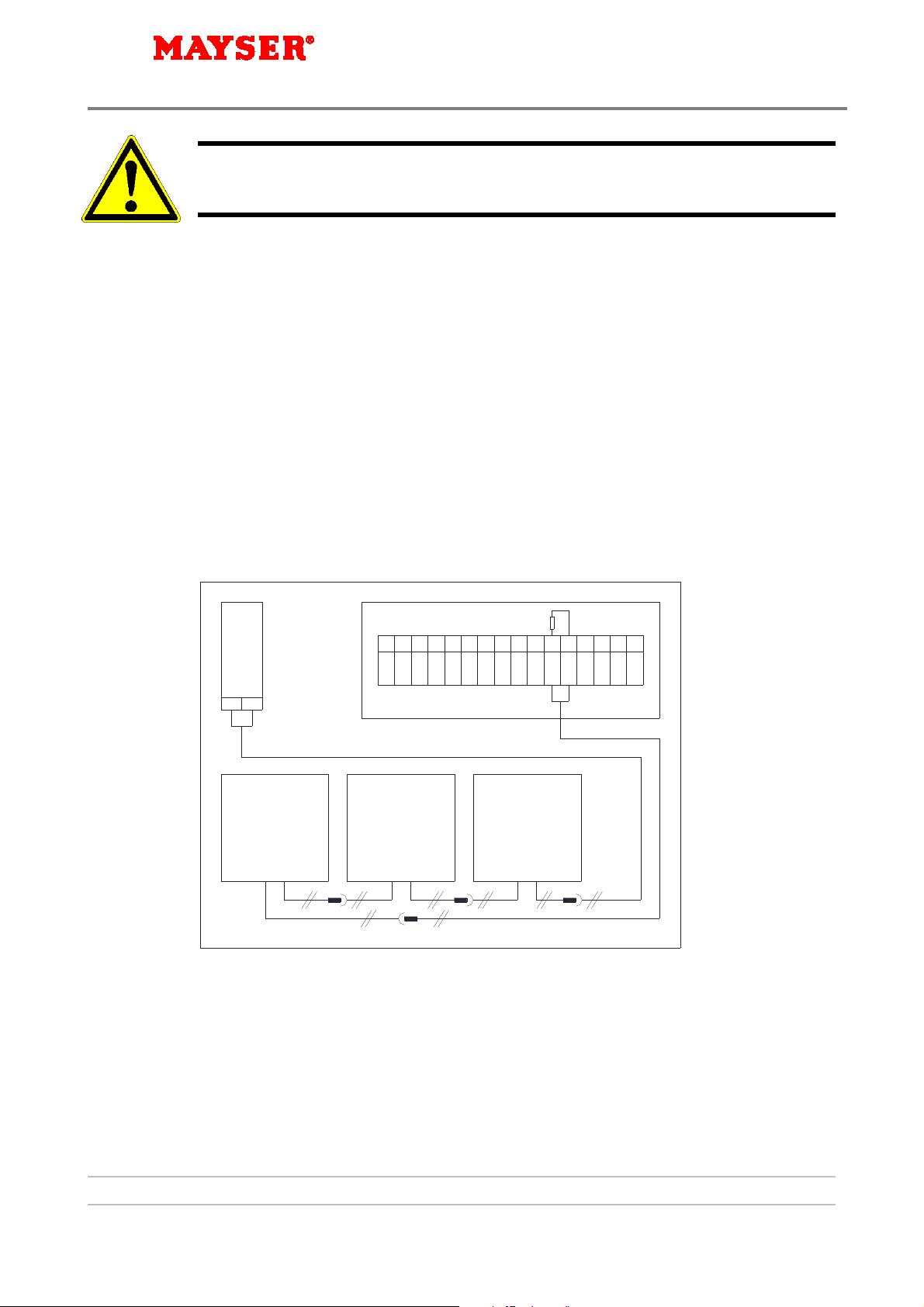
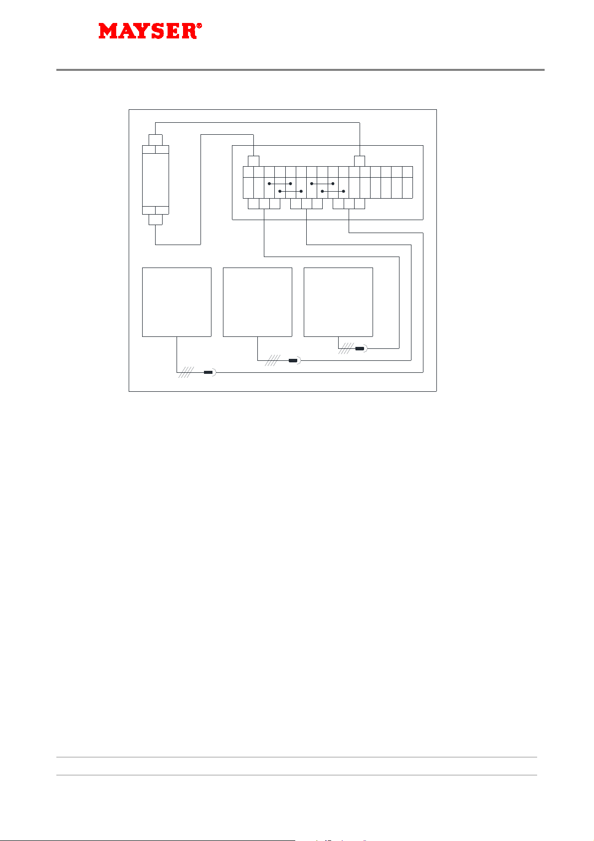
5.4 Laying cables
All ends of the connecting cable should be fitted with cable-end sleeves. Optionally plugs or
sockets may be used.
The type of wiring depends on the operating principle of your system.
1. Wire safety bumper cables to each other in accordance with the wiring plan (optional) or
according to the wiring diagrams illustrated under point 5.5. In doing so ensure the
following:
Connect the safety bumper cables to the cable glands.
Connect the safety bumper cables to the cable glands, observing the colour
coding.
Trim the cables if required.
If no plugs or plug sockets (optional) are available, double insulate soldering
points and seal with shrink tubing.
Only extend cables with double-insulated cables with short-circuit protection.

Safety technology
8 (12)
Assembly Manual Safety Bumper SB/BK and SB/W (NO/contact)
Rev.1 140805js
Cables can be damaged if laid incorrectly!
Do not crush or kink cables.
2. Lay cables and route to switch device.
Key to the following wiring diagrams:
BK Safety bumper with 4 connection lines as continuity signal
transmitter or to connect an external monitoring resistor
•Option 1: 2 x cable outlets á 2 lines
•Option 2: 1 x cable outlet with 4 lines
W Safety bumper with integrated monitoring resistor
SG Switch device
D Sub-distribution system with terminal blocks
R Resistor to monitor system function
(1k2 ±5% Ohm)
Colour coding:
bl blue sw black br brown
ws white rt red
Examples of two-wire technique
SG
Y1
D
BK
1 2 3 4 5 6 7 8 9 10111213141516
bl br
BK BK
Y2
R
Specifics:
• 2 cable outlets
• Clamped connections
(on site)
• Connection plug
(optional)
Fig. 5.4-1

Safety technology
9 (12)
Assembly Manual Safety Bumper SB/BK and SB/W (NO/contact)
Rev.1 140805js
SG
Y1
BK BK BK
Y2
R
Specifics:
• 2 cable outlets
• Connection plug
(optional)
• Terminal plug with
integrated terminal
resistance
Fig. 5.4-2
W BK BK
SG
Y1 Y2
Specifics:
• 2 cable outlets
• Combination of BK •
• and W
• Connection via • •
• Clamps (on site)
Fig. 5.4-3
br ws bl sw br ws bl sw bl br
2 (sw)
1 (br)
(sw) 4
BK BK
1 (br)
Y2
(bl) 3
2 (-)(-) 4
(bl) 3 3 (bl)
4 (sw)
(br) 1
(ws) 2(-) 2
(br) 1 3 (bl)
4 (-)
SG
Y1
D
W
1 2 3 4 5678 9 10111213141516
Specifics:
• 1 cable outlet
• Combination of BK •
• and W
• Connection plug
(optional)
• Clamped connections
(on site)
Fig. 5.4-4

Safety technology
10 (12)
Assembly Manual Safety Bumper SB/BK and SB/W (NO/contact)
Rev.1 140805js
Examples of four-wire technique
Y21 Y11
1 2
11 12
br ws bl sw
BK BK
Y22
SG
Y12
D
BK
1 2 3 4 5678 9 10111213141516
br ws bl sw br ws bl sw
Specifics:
• 1 cable outlet
• Connection plug
(optional)
• Clamped connections
(on site)
Fig. 5.4-5
5.5 Check function
Carry out the following steps for each cable of the bumper system:
1. Set the ohmmeter to measure in a high resistance range.
2. Connect the ohmmeter to the two cable conductors.
3. Measure the electrical resistance between the cable glands with activated and non-
activated bumper.
The measured resistance must have the following values:
•Bumper activated: < 150 Ohm
•Bumper not activated:
−Signal transmitter BK: 1 MOhm
−Signal transmitter W: 1k2 ±5% Ohm
Test failed?
If the resistance measurement does not give the required values, this may be caused by the
following:
•The cables of the individual bumpers are not correctly connected
•The cables are kinked or damaged

Safety technology
11 (12)
Assembly Manual Safety Bumper SB/BK and SB/W (NO/contact)
Rev.1 140805js
•The bumper is not adequately fixed and is sagging
•In the end position or the distance between the bumper and closing edge is too little
so that the bumper is already activated
Also check whether
•the safety bumper is functioning properly
•the safety bumper is undamaged
•the wires are installed correctly and undamaged
6 Maintenance and cleaning
6.1 Maintenance
During an inspection of the safety device to be conducted at regular intervals by an
authorised specialist, the entire safety device must be inspected to ensure that it is
functioning properly, taking into account the particular application; in case of doubt, contact
an authorised body for assessment.
Safety bumpers are maintenance free. Depending on the particular application and the
safety requirements, however, safety bumpers must be inspected to ensure that they are in
perfect working condition.
This inspection must include at least the following:
Check for proper working condition (damage) of the safety bumper and the connection
lines
Check the function of the analysis unit and of the safety module (if applicable)
If damaged, the safety function will not work!
In the case of discernible malfunctions or damage, the respective components must be
replaced immediately with original parts.
Conduct the inspection carefully. If there is any doubt, the components must be replaced,
since a malfunction can result in personal injury and material damage.
Recommended inspection interval: Daily function check

Safety technology
12 (12)
Assembly Manual Safety Bumper SB/BK and SB/W (NO/contact)
Rev.1 140805js
6.2 Cleaning
Clean the surface of the safety bumper with a damp cloth and mild cleaning agent.
After cleaning, wipe dry to remove any remaining moisture.
7 Disposal
The products included within the scope of delivery contain the following materials:
Safety bumper
•Aluminium (base plate)
•PU foam (body)
•Plastics
•Copper (cable, bumper inside)
Assembly accessories (optional)
•Steel (screws, nuts)
Packaging material
•Plastic, wood, cardboard, PU foam
•Aluminium composite foil, drying agent (optional for transport crate lining)
Observe the following when disposing of these materials:
Comply with all relevant national disposal regulations and legal requirements.
Provide the above list of materials to a disposal company commissioned with disposal of
the product.
Recycle or dispose of materials in an eco-friendly manner.
This manual suits for next models
1
Table of contents
Other MAYSER Safety Equipment manuals