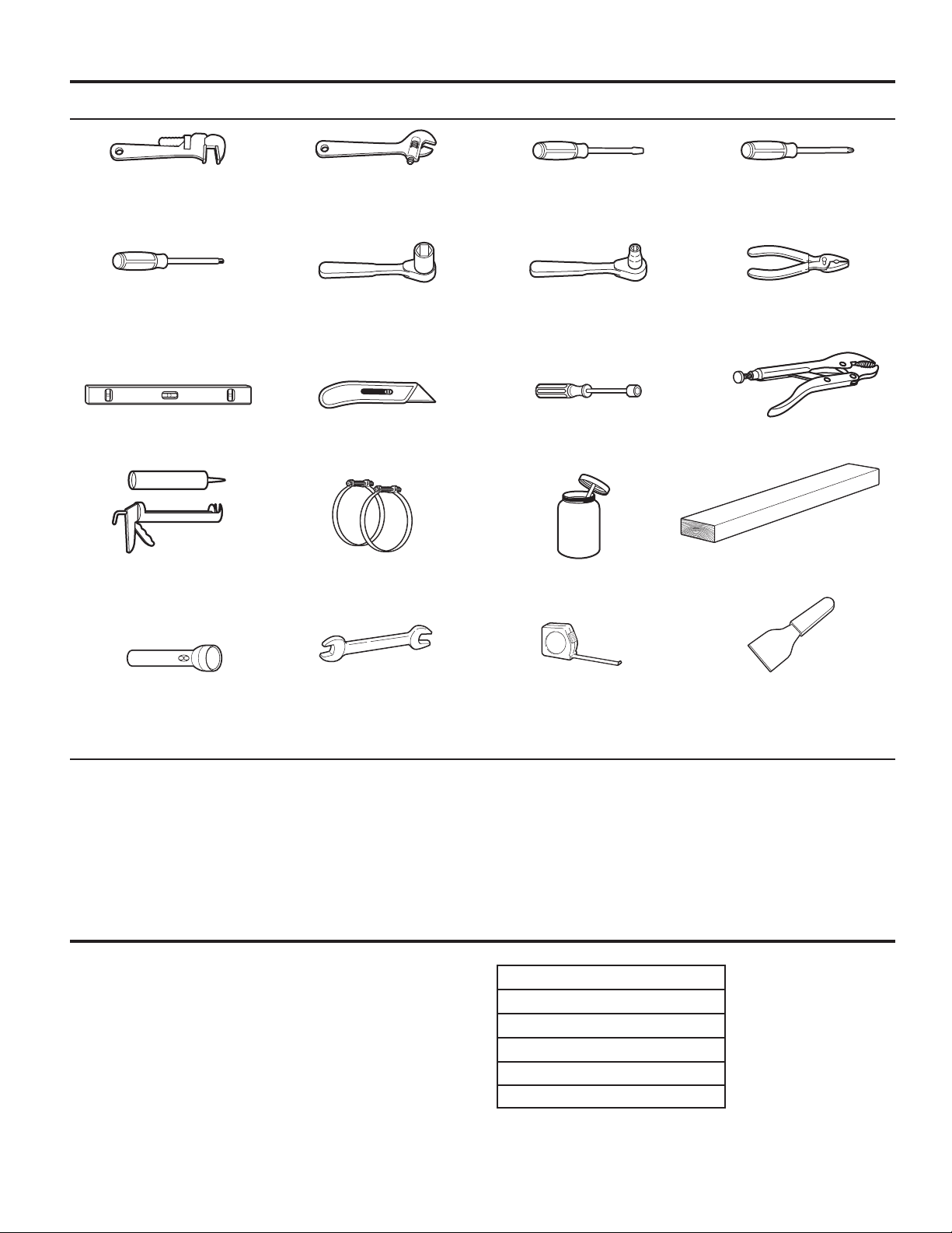
Maytag Commercial MDG28PD User manual

INSTALLATION
INSTRUCTIONS
ORIGINAL INSTRUCTIONS
COmmeRCIAL he dRyeR
GAS
INSTRUCTIONS
D’INSTALLATIONS
INSTRUCTIONS d’ORIGINe
SéCheUSe he COmmeRCIALe GAz
INSTRUCCIONES
DE INSTALACIÓN
INSTRUCCIONeS ORIGINALeS
SeCAdORA de he AGAS COmeRCIAL
ISTRUZIONI PER
L’INSTALLAZIONE
ISTRUzIONI ORIGINALI
ASCIUGATRICe he
COmmeRCIALe
AGAS
www.maytagcommerciallaundry.comW11591533B
MDG28PN/PR
MDG28PD

2
TABLE OF CONTENTS
Page
Dryer Safety ............................................................................ 3
Dryer Disposal ........................................................................ 6
Tools & Parts .......................................................................... 7
Dimensions/Clearances ........................................................ 8
Installation Requirements ..................................................... 9
Venting Requirements ......................................................... 12
Gas Supply Requirements .................................................. 14
Installing Leveling Legs, Payment Device, and Coin Box 15
Leveling ................................................................................ 16
Complete Installation .......................................................... 17
Reversing Door Swing (optional) ........................................ 18
Maintenance Instructions ................................................... 20
If You Need Assistance ....................................................... 20
Technical Specications – Gas Dryer ................................ 21
Electronic Control Setup Instructions ............................... 23
Warranty ............................................................................... 28
TABLE DES MATIÈRES
Page
Sécurité de la sécheuse....................................................... 29
Mise au rebut de la sécheuse.............................................. 33
Outils et pièces .................................................................... 34
Dimensions/distances de dégagement............................... 35
Exigences d’installation ...................................................... 36
Exigences concernant l’évacuation..................................... 39
Spécications de l’alimentation en gaz .............................. 42
Installation des pieds de nivellement, du dispositif de
paiement et de la caisse à monnaie .................................. 43
Mise à niveau ......................................................................... 44
Fin de l’installation .............................................................. 45
Inversion du sens d’ouverture de la porte (facultatif) ....... 46
Instructions d’entretien ....................................................... 48
En cas de besoin d’assistance ........................................... 48
Caractéristiques techniques – sécheuse à gaz ................ 49
Instructions de paramétrage
des commandes électroniques............................................ 51
Garantie.................................................................................. 57
ÍNDICE
Página
Seguridad de la secadora.................................................... 58
Desecho de la secadora ...................................................... 61
Herramientas y piezas ......................................................... 62
Dimensiones y espacios libres............................................. 63
Requisitos de instalación .................................................... 64
Requisitos de ventilación .................................................... 67
Requisitos del suministro de gas........................................ 69
Instalación de las patas niveladoras,
dispositivo de pago y caja de monedas ............................ 70
Nivelación.............................................................................. 71
Complete la instalación ....................................................... 72
Cambio del sentido de apertura de la puerta (opcional) .. 73
Instrucciones de mantenimiento ....................................... 75
Si necesita asistencia .......................................................... 75
Especicaciones técnicas – Secadora a gas ................... 76
Instrucciones de programación del control electrónico ... 78
Garantía ................................................................................ 84
INDICE
Pagina
Sicurezza dell'asciugatrice................................................... 85
Smaltimento dell'asciugatrice.............................................. 88
Attrezzi e parti........................................................................ 89
Dimensioni/Spazi minimi .................................................... 90
Requisiti per l'installazione................................................... 91
Requisiti di sato................................................................... 94
Requisiti per l'alimentazione a gas...................................... 96
Installazione dei piedini di messa in piano,
del dispositivo di pagamento e della gettoniera ................ 97
Messa in piano....................................................................... 98
Completamento dell'installazione ....................................... 99
Inversione dell'apertura dello sportello (opzionale)......... 100
Istruzioni per la manutenzione........................................... 102
Come richiedere assistenza............................................... 102
Caratteristiche tecniche: asciugatrice a gas.................... 103
Istruzioni di congurazione della centralina elettronica ... 105
Garanzia ............................................................................... 111

3
DRYER SAFETY
ʼnIt is recommended that the owner post, in a prominent location, instructions for the customer’s use in the event the customer
smells gas. This information should be obtained from your gas supplier.
ʼnPost the following warning in a prominent location.
FOR YOUR SAFETY
1. DO NOT USE OR STORE PETROL OR OTHER FLAMMABLE MATERIALS IN THIS APPLIANCE OR NEAR THIS APPLIANCE.
2. DO NOT SPRAY AEROSOLS IN THE VICINITY OF THIS APPLIANCE WHILE IT IS IN OPERATION.
3. DO NOT MODIFY THIS APPLIANCE.

4
DRYER SAFETY
WARNING – RISK OF FIRE/FLAMMABLE MATERIALS
This is an additional safety alert symbol that alerts you to the risk of fire.
WARNING:
FIRE OR EXPLOSION HAZARD
Failure to follow safety warnings exactly could result in serious injury, death or property
damage.
–
–
Do not store or use gasoline or other flammable vapors and liquids in the vicinity of this
or any other appliance.
WHAT TO DO IF YOU SMELL GAS:
–Installation and service must be performed by a qualified installer, service agency, or
the gas supplier.
•Do not try to light any appliance.
•Do not touch any electrical switch; do not use any phone in your building.
•Clear the room, building, or area of all occupants.
•Immediately call your gas supplier from a neighbor's phone. Follow the gas supplier's
instructions.
•If you cannot reach your gas supplier, call the fire department.

5
DRYER SAFETY
ʼnDo not install or store the dryer where it will be exposed to
the weather.
ʼnDo not tamper with controls.
ʼnClean dryer lint screen before or after each load.
ʼnDo not use this dryer without the lint screen in place.
ʼnDo not repair or replace any part of the dryer or attempt
any servicing unless specically recommended in this Use
and Care Guide or in published user-repair instructions
that you understand and have the skills to carry out.
ʼnFabric softeners, or similar products, should be used as
specied by the fabric softener instructions.
ʼnItems such as foam rubber (latex foam), shower caps,
waterproof textiles, rubber-backed articles, and clothes or
pillows tted with foam rubber pads should not be dried in
the tumble dryer.
ʼnThe nal part of a tumble dryer cycle occurs without
heat (cool-down cycle) to ensure that the articles are left
at a temperature that ensures that the items will not be
damaged.
ʼnWARNING: Never stop a tumble dryer before the end of
the drying cycle unless all items are quickly removed and
spread out so that the heat is dissipated. (Avoids risk of
spontaneous combustion).
ʼnWARNING: The appliance must not be supplied
through an external switching device, such as a timer, or
connected to a circuit that is regularly switched on and off
by a utility.
ʼnIn case of electrical supply failure, remove the load
quickly and spread it out to avoid risk of spontaneous
combustion.
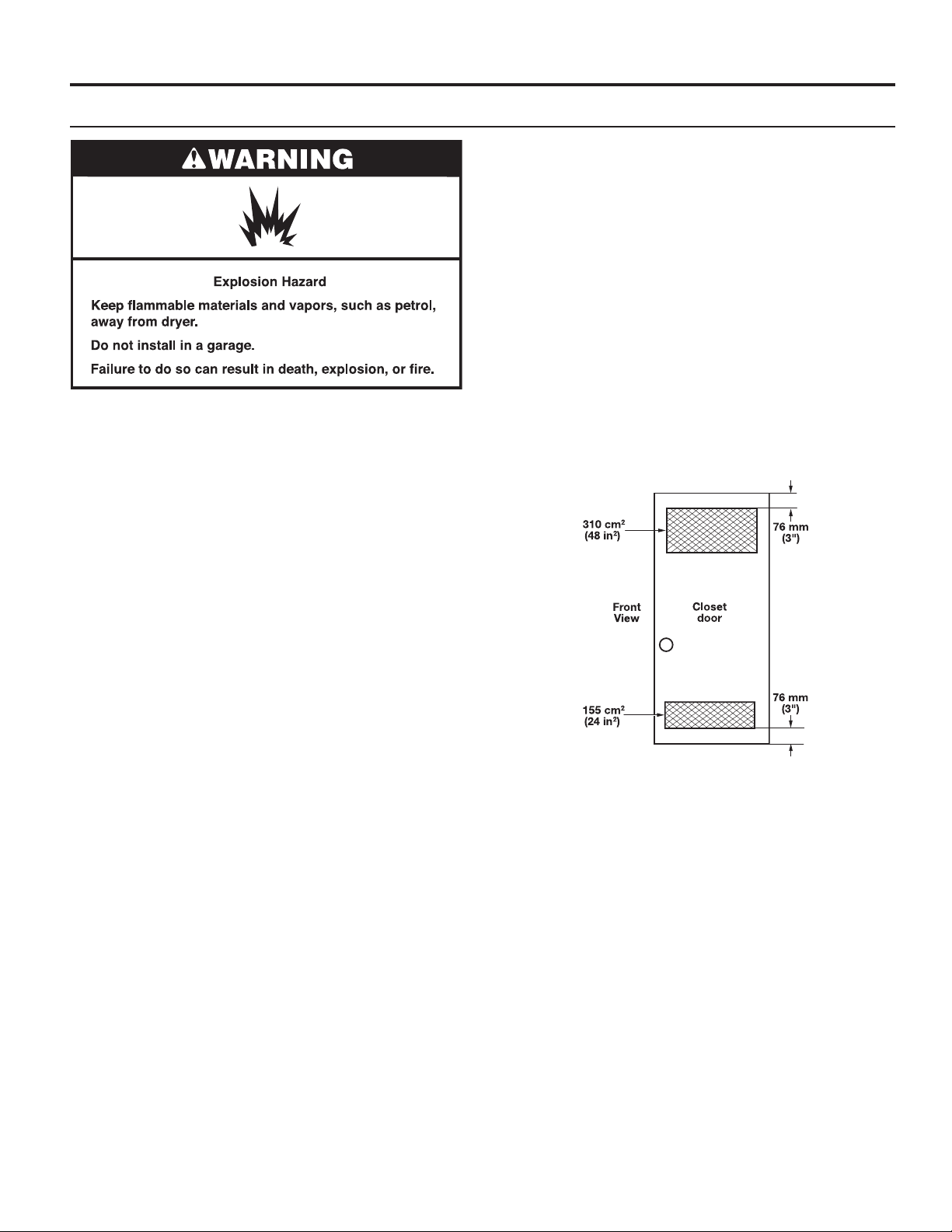
ʼnKeep area around the exhaust opening and adjacent
surrounding areas free from the accumulation of lint, dust,
and dirt.
ʼnVentilation openings in the base shall not be obstructed by
a carpet or similar object.
ʼnThis appliance is intended, but not limited, to be used in
public areas.
ʼnThis dryer is not intended for use by persons (including
children aged from 8years and above) with reduced
physical, sensory, or mental capabilities, or lack of
experience or knowledge, unless they have been given
supervision or instruction concerning use of the dryer by a
person responsible for their safety.
ʼnBefore the dryer is removed from service or discarded,
remove the door to the dryer compartment.
IMPORTANT SAFETY INSTRUCTIONS
WARNING: To reduce the risk of re, electric shock, or injury to persons when using the dryer, follow basic precautions, including
the following:
SAVE THESE INSTRUCTIONS
ʼnRead all instructions before using the dryer.
ʼnThis dryer is intended only for drying clothes and textiles
that have been washed in water. Do not use for any other
purpose.
ʼnWARNING: If you smell gas, do not use the dryer or any
electrical equipment nearby. Warn other people to clear
the area. Contact the dryer owner immediately.
ʼnOil-affected items can ignite spontaneously, especially
when exposed to heat sources such as a tumble dryer.
The items become warm, causing an oxidation reaction
in the oil. Oxidation creates heat. If the heat cannot
escape, the items can become hot enough to catch re.
Piling, stacking or storing oil-affected items can prevent
heat from escaping and so create a re hazard.
ʼnIf it is unavoidable that fabrics that contain vegetable or
cooking oil or that have been contaminated by hair care
products be placed in a tumble dryer, they should rst
be washed in hot water with extra detergent – this will
reduce, but not eliminate the hazard.
ʼnDo not dry articles that have been previously cleaned in,
washed in, soaked in, or spotted with petrol, dry-cleaning
solvents, other ammable, or explosive substances as
they give off vapors that could ignite or explode.
ʼnItems that have been soiled with substances such as
acetone, alcohol, petrol, kerosene, spot removers,
turpentine, waxes, and wax removers should be washed
in hot water with extra detergent before being dried in the
dryer.
ʼnDo not dry unwashed items in the dryer.
ʼnDo not use this dryer if industrial chemicals have been
used for cleaning. The possible presence of residual
quantities of aggressive or decomposed chemicals in
the load may produce damage to the dryer and harmful
fumes.
ʼnDo not allow children to play on or in the dryer. Close
supervision of children is necessary when the dryer is
used near children. Cleaning and user maintenance
shall not be made by children without supervision.
Children of less than 3 years should be kept away unless
continuously supervised.
ʼnIf drum rotation is blocked due to trapped textiles,
disconnect the dryer from the electrical supply before
gently removing the blockage.
ʼnIf the dryer is not heating, or appears to be defective or
damaged, do not use it. Contact the owner.

6
DRYER DISPOSAL
This appliance is marked according to the European directive 2012/19/EU on Waste Electrical and Electronic Equipment
(WEEE).
By ensuring this product is disposed of correctly, you will help avoid potential negative consequences for the environment
and human health, which could otherwise be caused by inappropriate waste handling of this product.
The symbol on the product, or on the documents accompanying the product, indicates that this appliance may not be
treated as household waste. Instead it shall be handed over to the applicable collection point for the recycling of electrical
and electronic equipment.
Disposal must be carried out in accordance with local environmental regulations for waste disposal.
For more detailed information about treatment, recovery and recycling of this product, please contact your local city ofce,
your household waste disposal service or the shop where you purchased the product.
MODEL NOMENCLATURE:
MDG – Maytag Dryer – Gas PN – Electronic Control – Non-Pay
## (e.g. 28) – Model Type Number PD – Electronic Control – Coin Drop Enabled
PR - Electronic Control - Card Ready
ʼnAdequate ventilation has to be provided to avoid the
back-ow of gases into the room from appliances burning
fuels, including open res.
ʼnThe dryer shall be disconnected from its power source
during service and when replacing parts.
ʼnIf this is not possible due to the construction of the dryer
or its installation, a disconnection with a locking system
in the isolated position shall be provided.
ʼnSee DIMENSIONS/CLEARANCES section for minimum
installation spacing requirements.
ʼnIEC Load Capacity: 10.5kg.
ʼnThis dryer is not tted with a supply cord and a plug.
Means for disconnection from the supply mains having
a contact separation in all poles that provide full
disconnection under overvoltage category III conditions
must be provided, otherwise means for disconnection
must be incorporated in the xed wiring in accordance
with the wiring rules.
ʼnDo not use an unlined masonry chimney as the ue for
this appliance.
ʼnIf an error code is displayed, contact the owner. The
owner shall call service.
ʼnDo not use or store ammable materials in or near this
appliance.
ʼnDo not place articles on or against this appliance.
ʼnExhaust air shall not be discharged into a ue which is
used for other appliances.
ʼnmeans that care is required to avoid causing a re
by igniting ammable material.
ʼnDo not reach into the dryer if the drum is moving.
ʼnOpening the dryer door will stop the function of the dryer.
ʼnWhen loading or re-loading the dryer, avoid touching hot
metal parts of the drum (burn risk).
ʼnRemove all objects from pockets such as lighters and
matches.
ʼnOnly authorized spare parts shall be used in the event of
failure.
ʼnThis appliance incorporates an earth connection for
functional purposes only.
ʼnThe dryer must not be installed behind a lockable door,
a sliding door or a door with a hinge on the opposite
side to that of the tumble dryer, in such a way that a full
opening of the tumble dryer door is restricted.
ʼnExhaust air must not be discharged into a ue which is
used for exhausting fumes from appliances burning gas
or other fuels.
ʼnThe fresh air ventilation openings into the room and into
the dryer must not be blocked or sealed.
ʼnEmergency stop control: After installation, access to
mains plug or disconnection from mains supply via a
double-pole switch must be ensured at all times in order
to ensure immediate deactivation of the dryer in case of
emergency.
ʼnThe interior of the dryer and dryer exhaust vent should be
cleaned periodically by qualied service personnel.
ʼnSee “Electrical Requirements” section for earthing
instructions.
DRYER SAFETY
SAVE THESE INSTRUCTIONS

7
Tools Needed:
(203 mm) 8" or (254 mm) 10" (203 mm) 8" or (254 mm) 10" Flat-Blade Screwdriver Phillips Screwdriver
Pipe Wrench Adjustable Wrench
that opens to (25 mm) 1"
TORX T20†Security (25 mm) 1" Hex-Head (8 mm) 5/16" Socket Wrench Pliers
Screwdriver or Bit Socket Wrench (that open to 39 mm (19/16"))
Level Utility Knife (6.35 mm) 1/4" Nut Driver Locking Pliers
Caulk Gun and Caulk Vent Clamps Pipe-joint compound (686 mm) 27" Wood Block
(for installing new exhaust vent) suitable for gas type
Flashlight (optional) (25.4 mm) 1" Open-End Ruler or Measuring Tape Putty Knife
Wrenches
TOOLS & PARTS
†TORX and T20 are trademarks of Acument Intellectual Properties, LLC.
NOTE: The circuit diagram for this dryer is located inside the side panel, within the Tech Sheets.
Parts Supplied:
nFoot boots (4)
nLeveling legs (4)
nPN/PR models: Card reader bezel, hardware.
These units are sold in multiple regions with different
requirements for measuring capacity. Below are a few of
the valid forms of measure posted on this product:
Dry Linen Capacity: A weight measure that reects a minimum
threshold for dry volume capacity that is needed for import tariff
purposes.
IEC Capacity: The capacity measure that represents the
maximum capacity of dry linens and textiles which the
manufacturer declares can be treated in a specic cycle.
Dry Linen Capacity
10.5 kg (23 lbs)
IEC Capacity
10.5 kg (23 lbs)
Sound Level
LpA: 58 dB(A) (kPa+/-10 dB(A))
SPECIFICATIONS

8
DIMENSIONS/CLEARANCES
Front View Side View Back View
Dimensions
Clearances
Recessed Front View
686 mm
(27")
965 mm
(38")
25 mm
(
1"
)
736 mm
(29")
921 mm
(361/4")
25 mm
(
1"
)
695 mm
(271/4")
203 mm
(8")
356 mm
(14")
25 mm
(1")
0 mm
(0")
381 mm
(15")
0 mm
(0")
159 mm
(61/4")
715 mm
(281/8")
89 mm
(31/2")
358 mm
(
14"
)
32 mm
(
11/4"
)
152 mm
(57/8")
Closet Side View

9
Your dryer can be installed in a basement, laundry room,
or recessed area.
Companion appliance location requirements should also be
considered.
IMPORTANT: Do not install or store the dryer where it
will be exposed to the weather. Proper installation is your
responsibility.
You will need:
ʼnA level oor with a maximum slope of 25 mm (1") under
entire dryer. Installing the dryer on soft oor surfaces,
such as carpets or surfaces with foam backing, is not
recommended.
ʼnA sturdy and solid oor to support the dryer with a total
weight (load) of 204 kg (450 lbs).
Installation clearances
ʼnThe location must be large enough to allow the dryer door to
be fully opened.
ʼnAdditional spacing should be considered for ease of
installation and servicing. The door opens more than 180°.
ʼnAdditional clearances might be required for wall, door, and
oor moldings.
ʼnAdditional spacing of 25 mm (1") on all sides of the dryer is
recommended to reduce noise transfer.
ʼnCompanion appliance spacing should also be considered.
When installing a gas dryer:
IMPORTANT: Observe all governing codes and ordinances.
ʼnCheck code requirements: Some codes limit or do not
permit installation of clothes dryers in garages, closets, or
sleeping quarters. Contact your local building inspector.
ʼnNOTE: For installation in Australia and New Zealand,
install dryer in accordance with AS/NZS 5601.1 and local
governance codes.
ʼnMake sure that lower edges of the cabinet, plus the back
and bottom sides of the dryer, are free of obstructions to
permit adequate clearance of air openings for combustion
air. See “Recessed Area and Closet Installation Instructions”
below for minimum spacing requirements.
ʼnDo not install on carpet.
Location
INSTALLATION REQUIREMENTS
Recessed Area and Closet Installation Instructions
This dryer may be installed in a recessed area or closet. The
dryer must not be installed behind a lockable door, a sliding door,
or a door with a hinge on the opposite side to that of the dryer
in such a way that a full opening of the dryer door is restricted.
For recessed area and closet installations, minimum clearances
can be found on the warning label on the rear of the dryer or in
“Dimensions/Clearances.”
The installation spacing is in millimeters and is the minimum
allowable. Additional spacing should be considered for ease
of installation, servicing, and compliance with local codes and
ordinances.
If closet door is installed, the minimum unobstructed air opening
in the top and bottom of the door shall be as depicted in the
diagram below. Louvered doors with equivalent air openings are
acceptable.
The dryer must be exhausted outdoors.
No other fuel-burning appliance may be installed in the same
closet as the dryer.
NOTE: For installation in Australia and New Zealand, refer
to AS/NZS 5601.1 for ventilation requirements.
NOTE: This dryer is not intended to be placed on top
of a washer.

10
INSTALLATION REQUIREMENTS
Electrical Requirements
This dryer is supplied without an electric cord and plug.
It must be connected by a competent electrician to a single-
phase electricity supply at the voltage shown on the dataplate,
using a suitable xed wiring installation in accordance with local
and national wiring regulations.
NOTE: In accordance with the European EMC Directive
(2014/30/EU), the maximum electricity supply system
impedance to which the electric dryer should be connected
is declared to be 0.054 Ω + j0.034 Ω.
NOTE: Electrical safety standards: The manufacturer has
chosen compliance with IEC/EN.60335 standards as the
most appropriate for this product.
ʼn A 3-wire circular cord of minimum conductor size 4.0mm2
cross-section area should be used.
ʼnThe electrical mains terminals are located behind the small
rear access panel (terminal block cover), and connections
should be made in accordance with the terminal markings.
ʼnInsure that a 3980399 Square Washer (part of furnished
W10545880 Bag Assembly - Square Washer) is installed
between the head of the terminal screw head and the
terminal tab. To install, remove the screw, place the
square washer on the screw, and partially reinsert the
screw. To minimize the potential for cross-threading,
initially rotate the screw counterclockwise and then
rotate clockwise. Bare wire must be placed between the
square washer and the terminal tab and secured by the
screw.
Torque to 4 Nm (35 in-lbf) minimum.
If codes permit and an additional earth bond wire is used,
it is recommended that a qualied electrician determine that
the earth bond path is adequate.
Recommended Earthing Method
It is your responsibility to contact a qualied electrical installer
to ensure that the electrical installation is adequate and in
conformance with all local codes and ordinances.
ʼnIf a crimped wire terminal is used instead of bare wire, it
must be located between the screw head and terminal
tab. Remove the screw and place the crimped contact
on the terminal tab with the crimp seam up, then reinsert
the screw. To minimize the potential for cross-threading,
initially rotate the screw counterclockwise and then
rotate until secure. Torque to 4 Nm (35 in-lbf) minimum.
ʼnA 5 A supply fuse should be used, and a switch having
a contact separation in both poles that provides full
disconnection under over-voltage category III conditions
must be incorporated into the xed wiring in accordance
with local wiring regulations. The dryer should be positioned
so that the disconnection switch is clearly visible and easily
accessible to the user. This disconnection switch also
provides the function of an emergency stop control
for the user.
ʼnA cord clamp bushing is provided on the dryer, and should
be tightened on completion of wiring. Remember to replace
the terminal access panel (terminal block cover).
Square Nut
Terminal
Square Washer
Screw
Screw Torque
Minimum
4.0mm²
4 Nm (35 in-lbf) Minimum
This is a 3-wire appliance which must be earthed.

11
INSTALLATION REQUIREMENTS
Gas Supply Requirements
IMPORTANT: Observe all governing codes and ordinances.
Gas Supply
Before installation, check that the local gas distribution
conditions, nature of gas and pressure, and the adjustment of
the appliance are compatible. Burner information will be found
on the model/serial rating plate in the door recess of the dryer.
If this information does not agree with the type of gas available,
see your dealer.
Natural Gas:
This dryer is factory adjusted for use with NATURAL GAS (G20),
and no further adjustment should be required at installation.
L.P. Gas:
This dryer is also certied for use with L.P. (propane or butane)
gases with appropriate conversion. No attempt shall be made
to convert the appliance from the gas specied on the model/
serial rating plate for use with a different gas without consulting
the serving gas supplier.
Conversion must be done by a competent service technician.
Gas conversion kit (European Country), part number
W10233219, is available for purchase from your dealer. Gas
conversion kit (Australia), part number W11603127, is available
for purchase from your dealer. Full instructions are supplied
with the kit.
Natural gas (France/Belgium):
This dryer is also certied for France/Belgium for use with
G20/G25 gases (20 mbar/25 mbar) with appropriate
conversion. No attempt should be made to convert this
appliance from the gas specied on the gas rating label for
use with a different gas without consulting the serving gas
supplier. Gas conversion must be done by a qualied gas
service technician. Conversion kit, part number (W10181947)
is available for purchase from your dealer. Full instructions are
supplied with the kit.
Supply line requirements:
A. Provide a rigid gas supply line to the dryer location. It
should be minimum 12.5 mm (1/2") ID. When acceptable
to the gas supplier and local codes, 10 mm (3/8") ID rigid
supply line may be used for lengths under 6.1 m (20'). Pipe-
joint compounds resistant to the action of L.P. gas must be
used.
NOTE: For installation in Australia and New Zealand, refer
to AS/NZS 5601 for pipe sizing details.
B. Gas connection to the dryer itself should be made by means
of a exible gas hose suitable for the appliance and gas
category in accordance with national installation regulations.
If in doubt, contact the gas supplier. It should be minimum
10 mm (3/8") ID.
A means of restraint should be used between the dryer and the
wall to avoid straining of the rigid gas supply when the dryer
is moved. An appropriate length of chain and a wall hook is
recommended.
The dryer gas inlet connection is a 3/8" NPT thread.
An adapter is supplied for conversion to standard ISO.228-1
thread (3/8" BSP).
Check for leaks by using an approved noncorrosive leak-
detection solution. Bubbles will show a leak. Correct any leak
found. A pressure measurement tapping is provided on the gas
valve within the dryer, accessible after removal of the lower
front panel.
The dryer must be disconnected from the gas supply piping
system during any pressure testing of that system.
The expected pressures for the gas supply are listed in Inches
of Water Column in the table below:
Gas Supply Minimum Maximum
Natural Gas 5.2 10.5
LP Gas 8.0 13.0
A.
B.
WARNING
Explosion Hazard
Use a new CSA International approved gas supply line.
Install a shut-off valve.
Securely tighten all gas connections.
If connected to LP, have a qualified person make sure
gas pressure does not exceed 13" (33 cm) water
column.
Examples of a qualified person include:
licensed heating personnel,
authorized gas company personnel, and
authorized service personnel.
Failure to do so can result in death, explosion, or fire.

12
VENTING REQUIREMENTS
WARNING: To reduce the risk of re, this dryer MUST BE
EXHAUSTED OUTDOORS.
IMPORTANT: Observe all governing codes and ordinances.
■Following these venting requirements will minimize ducting
air noise.
■Exhaust air must not be discharged into a ue which is used
for exhausting fumes from other appliances burning gas or
other fuels, including open res (i.e. available airow into
the room should match airow out from the room).
■Adequate ventilation must be provided to avoid the back
ow of gases into the room from appliances burning other
fuels, including open res.
■Dryer exhaust must not be connected into any gas vent,
chimney, wall, ceiling, attic, crawlspace, or a concealed
space of a building. Only rigid or exible metal vent shall
be used for exhausting.
■Do not use an exhaust hood with a magnetic latch.
■Only a 102 mm (4") heavy, metal exhaust vent and clamps
may be used.
■Do not use plastic or metal foil vent.
Rigid metal vent:
■Recommended for best drying performance and to avoid
crushing and kinking.
Flexible metal vent: (Acceptable only if accessible to clean)
■Must be fully extended and supported in nal dryer location.
■Remove excess to avoid sagging and kinking that may
result in reduced airow and poor performance.
■Do not install in enclosed walls, ceilings, or oors.
■The total length should not exceed 2.4 m (73⁄4ft).
■An exhaust hood should cap the vent to keep rodents
and insects from entering the building.
102 mm
(
4"
)
102 mm (4") heavy, metal exhaust vent
Elbows:
■45° elbows provide better airow than 90° elbows.
■Plan installation to use the fewest number of elbows
and turns.
■Allow as much room as possible when using elbows
or making turns. Bend vent gradually to avoid kinking.
■Vent outlet is located at the center of the bottom dryer back.
■The vent can be routed up, down, left, right, behind the
dryer, or straight out the back of the dryer.
Clamps:
■Use clamps to seal all joints.
■Exhaust vent must not be connected or secured with
screws or other fastening devices that extend into interior
of duct and catch lint. Do not use duct tape.
Better
Good
NOTES:
■Although usually each single-load dryer should have
an unobstructed outdoor air opening of
24 in2(154 cm2) (based on 1 in2[6.5 cm2] per 1,000BTU
[252kcal]), common makeup air openings are also
acceptable. Set up common openings so the makeup air
is distributed equally to all of the dryers. Keep in mind that
the coverage area must be increased by 33% to account
for the use of registers or louvers over the openings. Also,
makeup air openings should not be installed near the
location where exhaust vents exit the building.
■If using an existing vent system, clean lint from entire length
of the system and make sure exhaust hood is not plugged
with lint. Replace plastic or metal foil vents with rigid metal
or exible metal vents. Review “Vent System Chart” and,
if necessary, modify existing vent system to achieve best
drying performance.

13
12" min.
(305 mm)
102 mm (4") Diameter Exhaust Hoods
Box hood Louvered hood Angled hood
Vent Hoods
VENTING REQUIREMENTS
Exhaust hood must be at least 305 mm (12") from the ground
or any object that may be in the path of the exhaust (such as
owers, rocks, bushes, or snow).
Maximum Vent Length/Vent Connection
Maximum length of vent system depends upon the type of vent
used, number of elbows, and type of exhaust hood.
Vent System Chart (Rigid Metal Vent)
No. of 90˚ Turns Box and
Louvered Hood
Angled Hood
0 39.6 m (130 ft) 39.3 m (129 ft)
1 38.1 m (125 ft) 36.3 m (119 ft)
2 35.1 m (115 ft) 33.2 m (109 ft)
3 32.3 m (106 ft) 30.5 m (100 ft)
4 29.9 m (98 ft) 28.0 m (92 ft)
For vent systems not covered by the “Vent System Chart,”
see your parts distributor.
Provision must be made for enough air for combustion
and ventilation. (Check governing codes and ordinances.)
See “Recessed Area and Closet Installation Instructions”
in the “Location” section.
A 102 mm (4") outlet hood is preferred. However,
a 64 mm (21⁄2") outlet exhaust hood may be used.
A 64 mm (21⁄2") outlet creates greater back pressure than
other hood types. For permanent installation, a stationary vent
system is required.
Connect Vent
1. If connecting to existing vent, make sure the vent is clean.
2. Using a 102 mm (4") clamp, connect vent to exhaust outlet
in dryer.
Vent System Length
NOTE: Do not remove vent collar.
3. Tighten hose clamp with Phillips screwdriver.
4. Make sure the vent is secured to exhaust hood with
a 102 mm (4") clamp.
5. Move dryer into nal position. Do not crush or kink vent.
Make sure dryer is level.
Vent collar
305 mm minimum
(12")

14
The outside end of main vent should have a sweep elbow
directed downward.
If main vent travels vertically through the roof, rather than
through wall, install a 180° sweep elbow on end of vent at least
610 mm (2 ft) above surface of roof.
The opening in wall or roof shall have a diameter 13 mm (1⁄2")
larger than vent diameter. Vent should be centered in opening.
Do not install screening over end of vent for best performance.
minimum
A main vent can be used for venting a group of dryers. The
main vent should be sized to remove 5,663 L/min (200 CFM)
of air per dryer. Large-capacity lint screens of proper design
may be used in main vent if checked and cleaned frequently.
The room where the dryers are located should have make-up
air equal to or greater than CFM of all the dryers in the room.
A Back-draft Damper Kit is available from your distributor and
should be installed in the vent of each dryer to keep exhausted
air from returning into dryers and to keep exhaust in balance
within main vent. Unobstructed return air openings are required.
Each vent should enter the main vent at an angle pointing in
the direction of the airow. Vents entering from the opposite
side should be staggered to reduce the exhausted air from
interfering with the other vents.
The maximum angle of each vent entering the main vent should
be no more than 30°.
Keep air openings free of dry-cleaning uid fumes. Fumes
create acids which, when drawn through the dryer heating
units, can damage dryers and items being dried.
A clean-out cover should be located on the main vent for
periodic cleaning of the vent system.
If an Exhaust Hood Cannot Be Used Multiple Dryer Venting
VENTING REQUIREMENTS
minimum
30˚ maximum
Air ow
*Minimum clearance above
any accumulation of snow,
ice, or debris such as leaves
1. Remove red cap from gas pipe.
2. Connect gas supply to dryer. If the exible gas hose has
10 mm (3/8") BSP thread, use the supplied conversion thread
adapter. Use pipe-joint compound resistant to the action
of L.P. gas for gas connections.
If necessary for service, open the toe panel. Use a putty knife
to press on the 2 toe panel locks located at the top of the toe
panel. Pull downward on the toe panel to open. Toe panel is
hinged at the bottom.
3. Open the shut-off valve in the gas supply line.
4. Test all connections by brushing on an approved
noncorrosive leak-detection solution. Bubbles will show
a leak. Correct any leaks found.
Make Gas Connection
GAS SUPPLY REQUIREMENTS
WARNING
Explosion Hazard
Use a new CSA International approved gas supply line.
Install a shut-off valve.
Securely tighten all gas connections.
If connected to LP, have a qualified person make sure
gas pressure does not exceed 13" (33 cm) water
column.
Examples of a qualified person include:
licensed heating personnel,
authorized gas company personnel, and
authorized service personnel.
Failure to do so can result in death, explosion, or fire.

15
INSTALLING LEVELING LEGS, PAYMENT DEVICE, AND COIN BOXINSTALLING LEVELING LEGS, PAYMENT DEVICE, AND COIN BOX
The payment device, control panel lock and key, and coin box
lock and key are not included and are available from usual
industry sources.
1. Prepare dryer for leveling legs
NOTE: Slide dryer onto cardboard or hardboard before moving
to avoid damaging oor covering.
Using two or more people, move dryer to desired installation
location.
Take tape off front corners of dryer. Open dryer and remove
the literature and parts packages. Wipe drum interior with damp
cloth to remove any dust.
Take two cardboard corners from the dryer carton and place
them on the oor in back of the dryer. Firmly grasp body of the
dryer and gently lay it on its back on the cardboard corners.
2. Screw in leveling legs
Examine leveling legs and nd diamond
marking. Screw legs into leg holes by
hand. Use an adjustable wrench or
25 mm (1") hex-head socket wrench to
nish turning legs until diamond marking
is no longer visible. Then t a covered foot
boot over each leg foot. A longer leveling foot
(Part Number 279810) is available if needed
on extremely sloped oors.
To protect the oor, use a large piece of cardboard from the
dryer carton. Stand dryer up on the cardboard. Slide the dryer
until it is close to its nal location. Leave enough room for
electrical connection and to connect the exhaust vent.
3. Install payment device and coin box
Remove the service door of the meter case by lifting
it up at the back. If applicable, install the money-accepting
device. (Refer to manufacturer’s instructions for proper
installation.)
Replace the meter case service door. Put the coin vault
with lock and key in the meter case opening.
Remove cardboard or hardboard from under dryer. Adjust
the legs of the dryer up or down until the dryer is level.
Foot
Diamond
marking

16
1. Remove cardboard from beneath dryer. Place a level on top
edges of dryer, checking each side and front. If not level, tip
dryer and adjust feet up or down as shown in Steps 3 and 4,
repeating as necessary.
LEVELING
Leveling your dryer properly reduces excess noise and vibration.
Not Level LEVEL Not Level
2. Grip dryer from top and rock back and forth, making sure all
four feet are rmly on oor. Repeat, rocking dryer from side
to side. If dryer rocks, go to Step 3 and adjust leveling feet.
If all four feet are in rm contact with oor, go to Step 4.
4. When dryer is level and all four feet are rmly in contact
with the oor, use a 25 mm or (1") open-end or adjustable
wrench to turn nuts on leveling feet tightly against dryer
cabinet.
HELPFUL TIP: You may want to prop dryer with wooden
block.
3. If dryer is not level, remove the rubber boot if used; then use
an adjustable wrench or 25 mm (1") hex-head socket wrench
to turn legs until adjustment is completed. Check levelness of
dryer after all feet are rmly touching the ground and the level
shows dryer top to be level front to back and side to side.
HELPFUL TIP: You may want to prop up front of dryer
about 102 mm (4") with a wood block or similar object
that will support weight of dryer.

17
1. Check the electrical requirements. Be sure that you have
the correct electrical supply and the recommended earthing
method. See “Electrical Requirements.”
2. Check that all parts are now installed. If there is an extra part,
go back through the steps.
3. Check that you have all of your tools.
4. Dispose of/recycle all packaging materials.
5. Plug into an earthed outlet, or connect power.
WARNING
Electric Shock Hazard
This dryer must be earthed.
Securely tighten all electrical connections.
Failure to do so can result in death, fire, or
electric shock.
COMPLETE INSTALLATION
6. Check dryer operation. Using a full heat cycle, let the dryer
run for at least 5 minutes. Dryer will stop when time is
used up.
NOTE: Dryer door must be closed for dryer to operate. When
door is open, dryer stops, but timer continues to run. To restart
dryer, close door and press cycle keypad.
7. If the burner does not ignite and you can feel no heat inside
the dryer, shut off dryer for 5 minutes. Check that all supply
valve controls are in “ON” position and that the electrical
cord is plugged in. Repeat 5 minutes test.

18
REVERSING DOOR SWING (OPTIONAL)
Remove the Door Assembly
1. Place a towel or soft cloth on top of dryer or work space
to avoid scratching of the surface.
2. Remove 3 of the 4 screws that hold the door hinge on the
front panel of the dryer. Partially loosen the remaining screw
with keyhole opening and lift the door off the screw.
3. Lay the door assembly on a previously prepared at surface
with the inside (inner door assembly) facing up, and remove
6 Phillips-head screws to release outer door assembly from
inner door assembly.
NOTE: It is important that you remove only 6 indicated screws.
4. Lift the inner door assembly off outer door assembly.
5. Rotate outer door 180°.
Reverse Hinge
1. Use a small at-blade screwdriver to remove 2 plug
strips from the inner door. Slide the head of the screwdriver
under the plugs, without scratching inner door surface, and
lift up strip.
2. Remove the 4 screws that attach to inner door hinge.

19
REVERSING DOOR SWING (OPTIONAL)
3. Move hinge to other side. Reinstall 4 screws.
4. Reinstall plug strips on opposite side of the inner door.
5. Check for ngerprints on the glass. Clean if necessary.
Replace the Door Assembly
1. Place the inner door assembly inside the outer door
assembly.
2. Reassemble the inner and outer door assemblies with
the 6 screws.
Reverse the Strike
1. Use a small at-blade screwdriver to remove plug strip from
the dryer door opening. Slide the head of the screwdriver
under the plugs, without scratching dryer surface, and lift
up strip.
2. Remove the strike using a Phillips screwdriver.
3. Insert strike on the opposite side.
Reinstall the Door
1. Partially insert the third screw from the top; then slide the
hinge onto this screw while hooking the hinge into the front
panel hole. Reattach door to dryer front panel with the
remaining 3 screws.
2. Check for ngerprints on the glass. Clean if necessary.
3. Close door and check that it latches securely.

20
MAINTENANCE INSTRUCTIONS
ʼnClean lint screen before and after each cycle.
ʼnRemoving accumulated lint:
From inside the dryer cabinet:
Lint should be removed every
2years or more often, depending
on dryer usage. Cleaning should
be done by a qualied person.
From the exhaust vent:
Lint should be removed every
2 years, or more often, depending
on dryer usage.
ʼnKeep area around dryer clear and free from combustible
materials, gasoline, and other ammable vapors and liquids.
ʼnKeep dryer area clear and free from items that would
obstruct the ow of combustion and ventilation air.
Direct all requests for service to the Maytag Commercial
Laundry Distributor that sold the appliance.
When calling, please know the purchase date and the
complete model and serial number of your appliance. This
information will help us to better respond to your request.
IF YOU NEED ASSISTANCE
If dryer does not operate, check the following:
ʼnElectrical supply is connected.
ʼnCircuit breaker is not tripped or house fuse is not blown.
ʼnDoor is closed. Listen closely to hear the door switch
activate.
ʼnCycle selection keypad has been pushed rmly and display
shows cycle time.
ʼnCheck that gas supply shut-off valves are set in open
position.
This manual suits for next models
2
Table of contents
Languages:
Other Maytag Commercial Dryer manuals

Maytag Commercial
Maytag Commercial MLE27PD User manual

Maytag Commercial
Maytag Commercial MDG20MNBGW User manual

Maytag Commercial
Maytag Commercial MLG45 User manual

Maytag Commercial
Maytag Commercial MDE28PN User manual

Maytag Commercial
Maytag Commercial MDE28PD User manual

Maytag Commercial
Maytag Commercial MDG17MN User manual

Maytag Commercial
Maytag Commercial MEDP575GW User manual

Maytag Commercial
Maytag Commercial MLG27PN User manual

Maytag Commercial
Maytag Commercial MGD20MNTGW User manual

Maytag Commercial
Maytag Commercial YMEDP575GW User manual