MCi Designplan GROUND LINER ETL User manual

GROUND LINER®ETL
Installation Instrucions
Designplan Lighting, Inc., 79 Trenton Ave., Frenchtown NJ, 08825. T.908-996-7710 F.908-996-7042

INDEX
3
4
5
6
9
13
14
15
REFERENCES
TECHNICAL DATA
MEASURES
INDICATIONS
INSTALLATION
EXTRACTION TOOL
RGB CONNECTIONS
MONOCOLOR CONNECTIONS
SAFETY PRECAUTIONS 17

Ground Liner®ETL TECHNICAL GUIDE
GROUND LINER®ETL
PRODUCT CODES
Ground Liner® 1000 x 33 mm. Opal white 7101121/C02
Ground Liner® 1000 x 33 mm. Opal warm white 7101121/C 22
Ground Liner® 1000 x 33 mm. Opal blue 7101121/C09
Ground Liner® 1000 x 33 mm. Opal RGB 7101121/C11
Ground Liner® 500 x 33 mm. Opal white 7101123/C02
Ground Liner® 500 x 33 mm. Opal warm white 7101123/C 22
Ground Liner® 500 x 33 mm. Opal blue 7101123/C09
Ground Liner® 500 x 33 mm. Opal RGB 7101123/C11
*Ground Liner® 250 x 33 mm. Opal white 7101124/C02
*Ground Liner® 250 x 33 mm. Opal warm white 7101124/C22
*Ground Liner® 250 x 33 mm. Opal blue 7101124/C09
*Ground Liner® 250 mm. only suitable for end of the line
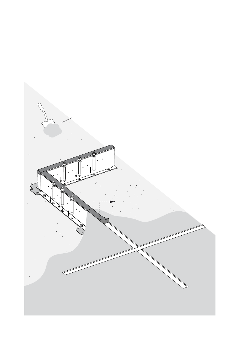
Recessed box 1000 mm. Ground Liner® Silver 7101191/C12
Recessed box 500 mm. Ground Liner® Silver 7101193/C12
Recessed box 250 mm. Ground Liner® Silver 710119 4/C12
Options
The standard version in RGB model is delivered with DMX.
Also available with DALI control.

Ground Liner®ETL TECHNICAL GUIDE
GROUND LINER®ETL
TECHNICAL DATA
MECHANICAL SPECIFICATIONS
Version 250 mm. 500 mm. 1000 mm.
*Measures 130 x 75 x 250 mm. 130 x 75 x 500 mm. 130 x 75 x 1000 mm.
Weight Luminaire 0,51 kg. 1,02 kg. 2,03 kg.
Recessed box 0,68 kg. 1,23 kg. 2,35 kg.
Lens EPOXY Resin
Housing
20 micras aluminium
Recessed box
Pressure load 30 kN
Protection class IP66/68
Impact resistance IK10
Temperature
range -30 °C a +70 °C -22 °F to +158 °F
* Recessed box included
ELECTRICAL SPECIFICATIONS
Input voltage 24V DC
Protection class III
Control type
Monocolor PWM / CA (Common anode)
RGB DMX512-A / DALI
250 mm. 500 mm. 1000 mm.
LED quantity
Monocolor
20 40 80
Power consumption 3,84 W 7,68 W 15,36 W
LED quantity
RGB
N.A. 30 60
Power consumption N.A. 8,7 W 17,3 W
N.A. Not available

Ground Liner®ETL TECHNICAL GUIDE
GROUND LINER®ETL
DIMENSIONS
Inner Body
Outer Body
1000 / 500 / 250 mm.
(39,4 / 19,7 / 9,85 in)
35 mm.
(1,38 in)
75 mm.
(2,95 in)
125 mm.
(4,92 in)
30 mm.
(1,18 in)
1000 / 500 / 250 mm.
(39,4 / 19,7 / 9,85 in)
43 mm.
(1,69 in)
1000 / 500 / 250 mm.
(39,4 / 19,7 / 9,85 in)
35 mm.
(1,38 in)
75 mm.
(2,95 in)
125 mm.
(4,92 in)
30 mm.
(1,18 in)
1000 / 500 / 250 mm.
(39,4 / 19,7 / 9,85 in)
43 mm.
(1,69 in)

Ground Liner®ETL TECHNICAL GUIDE
GROUND LINER®ETL
INDICATIONS
Never use the product as concrete expansion joint.
Must be taken into consideration the concrete expansions.
Leave separation of 1 mm as minimum between two luminaires every two meters of installed product.
Do not take out the foam joint stuck to the box, it is needed to absorb possible material expansions.
For concrete installation, shoETLd be used a covering over the concrete in order to improve the pro-
tection against external chemical agents.
Leave the 20 cm of drainage is under installer’s responsibility. Not leaving it, may cause the damage of
the luminaire and consequent loss of warranty.
READ BEFORE INSTALLING THE
PRODUCT!

Ground Liner®ETL TECHNICAL GUIDE
1
1
2
3
Place it to avoid entrance of dirt
NOT INCLUDED
GROUND LINER®ETL
INSTALLATION

Ground Liner®ETL TECHNICAL GUIDE
1
2
3
GROUND LINER®ETL
INSTALLATION

Ground Liner®ETL TECHNICAL GUIDE
Pour the concrete carefully around the
luminaires
Remove cover
GROUND LINER®ETL
INSTALLATION

GLETL.IMT-152.V1.11.
Ground Liner®ETL TECHNICAL GUIDE
Concrete detail
Luminaire position
Luminaire place
5mm
FILL UP WITH CONCRETE UP TO 5mm OVER THE BOX LEVEL
20 cm
MINIMUM
DRAINAGE
GROUND LINER®ETL
INSTALLATION

Ground Liner®ETL TECHNICAL GUIDE
Once the luminaire has been placed, the lateral sides must be sealed with BOSTIK POLIURETANE for OUTDOOR
applications
GROUND LINER®ETL
INSTALLATION

GLETL.IMT-152.V1.13.
Ground Liner®ETL TECHNICAL GUIDE
Next Luminaire
Next Luminaire
GROUND LINER®ETL
INSTALLATION

Ground Liner®ETL TECHNICAL GUIDE
Centric extraction
End extraction
GROUND LINER®ETL
EXTRACTION TOOL

Ground Liner®ETL TECHNICAL GUIDE
GROUND LINER®ETL
RGB CONNECTIONS
M030360
DMX
Output 1
DMX
Output
2
3
4
DMX 512-A up to 5 luminaires
DMX 512-A more than 5 luminaires
DMX Controller
DMX Amplier
MCI
GRUPO
DMX CONTROLLER
MCI
GRUPO
DMX CONTROLLER
DMX Controller
DATA
A
B
PSU 24V DC - 320W
B
24V DC
24+
(White)
GND-
(Black)
DMX+
(Brown)
DMX-
(Blue)
Maximum 5 luminaires of 1m. per DMX output with PSU 24V
DC - 320W
Maximum 100 meters from controller to rst luminaire
Maximum 100 meters from amplier to last luminaire
Maximum 5 luminaires of 1m. per DMX controller with PSU
24V DC - 150W
Maximum 100 meters from controller to rst luminaire
Follow connection diagram type for DALI installations
This connection to be
made inside outer body This connection to be
made inside outer body
This connection to be
made inside outer body
M030360
M030360
Remote power supply
to be connected to fixtures
inside a nema style (or equal)
enclosure (by others), using
appropriate wirenuts.
NOTE:
All wiring outside of outer
bodies
must be run thru conduit!

Ground Liner®ETL TECHNICAL GUIDE
CONTROLLER
DIMMABLE MONOCOLOR
MONOCOLOR NO DIMMABLE
Dimmer Basic
Dimmer Basic
Lineardrive 720
Lineardrive
PSU 24V DC - 320W
PSU 24V DC - 320W
PSU 24V DC - 320W
A
B
Maximum 5 luminaires of 1 meter (15 meters) per line connected to
lineardrive 720D (PSU 24V DC - 320W)
Maximum 5 meters from power supply to rst luminaire
Maximum 3 lines of 5 luminaires of 1 meter each line in parallel connection
to PSU 24V DC - 320W (15m.)
Each line must have one dimmer basic
Maximum 5 meters from power supply to rst luminaire
M030360
Maximum 5 luminaires of 1 meter each line connected with PSU 24V DC -
320W (15m.)
Maximum 5 meters from power supply to rst luminaire
POWER + CONTROL
3
2
Line
23
Line
2
3
GROUND LINER®ETL
MONOCOLOR CONNECTIONS
This connection to be
made inside outer body
This connection to be
made inside outer body
This connection to be
made inside outer body
M030360
M030360
NOTE:
All wiring outside of outer
bodies
must be run thru conduit!
Remote power supplies
to be connected to fixtures
inside a nema style (or equal)
enclosure (by others), using
appropriate wirenuts.
Remote power supply
to be connected to fixtures
inside a nema style (or equal)
enclosure (by others), using
appropriate wirenuts.

Ground Liner®ETL TECHNICAL GUIDE
max. 5 uds. x1m
max. 5 uds. x1m max. 5 uds. x1m
max. 5 uds. x1m
24V DC
-
PWM (Blue)
GND- (Black)
24+ (White)
24+ (Brown)+
Steady Light
Lineardrive 720D DMX/DALI/0-10V 24V DC
Power Supply
24 V DC 320 W +
-
Next line
24V DC
-
PWM (Blue)
GND- ( Black)
24+ (White)
24+ (Brown)+
LINEARdrive 720D
Group 1
GND 1
GND 2
GND 3
GND 4
DMX +
+
-
DMX -
DMX shield
LEDSync +
Dali IN
Dali IN
Dali OUT
Dali OUT
LEDSync -
LEDSync shield
Group 2
Group 3
Group 4
M050206
Power Supply
24 V DC 320 W
Next line
+ +
- -
GROUND LINER®ETL
MONOCOLOR CONNECTIONS

Ground Liner®ETL TECHNICAL GUIDE
GROUND LINER®ETL
SAFETY PRECAUTIONS
Use as directed
This product serves exclusively lighting purposes and may:
• Expose to strong mechanical loads or strong contamination.
• Only be installed and operated after a condition inspection if the product is dirty or has been
moistened through storage.
• Not be modied or converted.
If these points named above are not adhered to, a short circuit or electrical shock may occur!
Installation
The complete installation must be done by an electrical expert or a specialized maintenance team, who is familiar with valid directives.
Attention: Switch o power of the mains supply or respectively of the connection lead before doing any works.
Use only parts, which are supplied with the product or are described as accessories! Otherwise the product or the installation might
not be suciently safe!
Indication for the installer: In case you do not install a completely supplied system (with
transformer), you are considered a “manufacturer” by the low-voltage directive. In this case
you are required to ensure the conformity of the whole system and declare it by attaching
the CE-sign.
Installation place
Make sure that the product is mounted on a stable, even and tilt-xed background. Note the minimum distances in the ceiling.
Attention: Do not cover the product, especially not with insETLating materials.
Operation - Information for the user
Operate the product only if it is working correctly. Switch o the product with a malfunction immediately and operate it again only
after examination by an electrical specialist. This is the case, when:
• Visible damages appear.
• The product does not work.
• Smoke, steam or crackling sounds appear.
• An overheating is recognisable.
Repairs of the product or work on mains voltage-prominent sections may only be carried out by qualied electricians.
Attention: Exists mortal danger from an electric shock!
How to avoid failure and re risk
• Do not cover the product - provide free air circETLation!
• Do not hang or fasten anything on the product, especially no decoration.
• Never let children play unsupervised with electric products!
• Children can not always estimate dangers in dealing with electric energy correctly.
Disconnect the product from power, before you…
• Clean or maintain the product.
• Do any works on the product or its components (electric expert).

IMT-152 v.01
Ground Liner®ETL
Designplan Lighting, Inc., 79 Trenton Ave., Frenchtown NJ, 08825. T.908-996-7710 F.908-996-7042
This manual suits for next models
14
Table of contents
Other MCi Lighting Equipment manuals
Popular Lighting Equipment manuals by other brands

BOS Lighting
BOS Lighting AMADEUS H250 quick start guide

AQUAVIVO
AQUAVIVO PLANTPRO 60 quick start guide

Elation
Elation Design Spot 300E manual

Clevertronics
Clevertronics CleverEVAC LP UltraBlade DYGC UP Series Installation & maintenance instructions

X4-Life
X4-Life 701753 instruction manual

Martin Professional
Martin Professional Xciter user manual