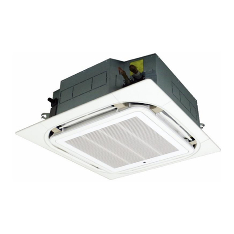
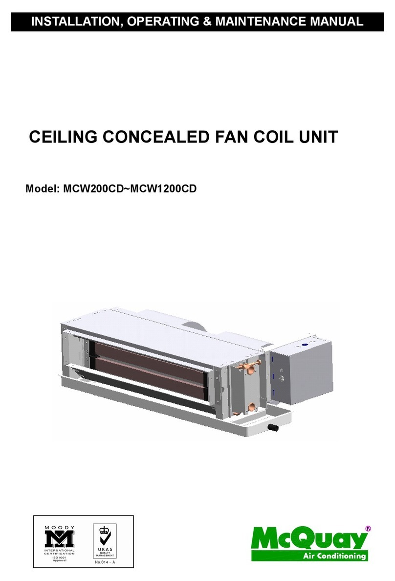
McQuay MFU-C User manual

PRODUCT MANUAL
PRODUCT MANUALPRODUCT MANUAL
PRODUCT MANUAL
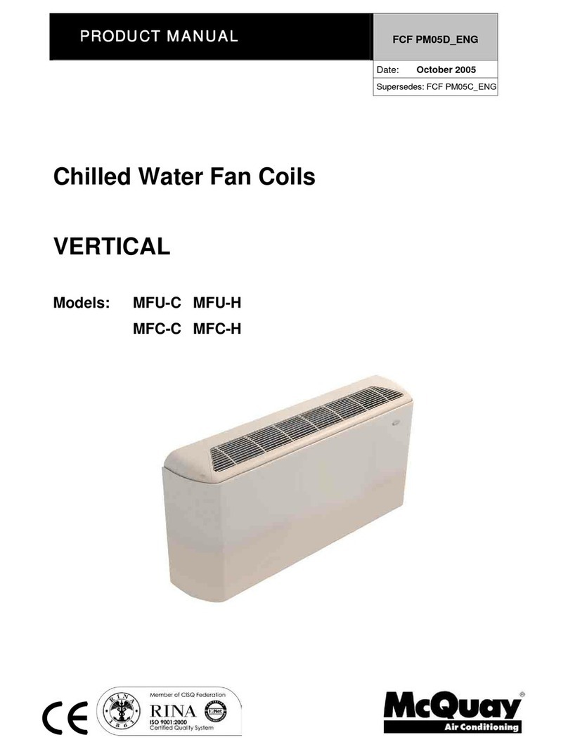
Chilled Water Vertical Fan Coils
Models: MFU-C MFU-H
MFC-C MFC-H

CHILLED WATER FAN COILS – McQuay
1
INDEX
VerticalFanCoil page 2
GeneralCharacteristics page 3
Technicaldata page 7
SoundLevel page 9
OperatingLimitsandPressuredrops page 11
OutlinesandDimensions page 12
Installation page 14
ControlFeatures page 18
-ElectroniccontrollerAC2800B page 18
-ElectroniccontrollerAC2800 page 19
-ElectronicthermostatAC8000+WirelessControllersAC5300 page 21
-MechanicalThermostatAC512/AC513 page 23
WiringDiagrams page 24
TechnicalDataatConditionsNonStandard page 26
SAFETY PRECAUTIONS
Before installing the air conditioner, please read the following safety precautions carefully.
Installation and maintenance are to be performed by qualified persons who are familiar with local
code and regulation, and experienced with this type of appliance.
All field wiring must be installed in accordance with the national wiring regulation.
Ensure that the rated voltage of the unit corresponds to that of the nameplate before
commencing wiring work according to the wiring diagram.
The unit must be GROUNDED to prevent possible hazard due to insulation failure.
Confirm that the unit has been switched OFF before installing or servicing the unit.
MFU(MFC)0811-E4
Part No:M08019000004
Warning

CHILLED WATER FAN COILS – McQuay
2
VERTICAL FLOW FAN COIL
VERTICAL FLOW FAN COILVERTICAL FLOW FAN COIL
VERTICAL FLOW FAN COIL
THE NEW SHAPE OF WELLNESS
The new series F of fan coil with vertical air flow is characterised by flexibility in performance and quiet
operation to offer a total wellness. It represents one of the most cost-effective solutions to provide a
comfortable environment for both commercial and residential applications.
The series features 8 sizes, with cabinet for floor or wall installation and
chassis for concealed installations.
The units are available in the 2-pipes version with 3 or 4-rows coil –
nominal cooling capacity from 1.3 to 8.0kW; nominal heating capacity from
2.2 to 12.0kW – or in the 4-pipes version – nominal cooling capacity from
1.2 to 8.0kW; nominal heating capacity from 2.3 to 13.0kW. 2-pipes version
models can also be equipped with electrical heaters, from 0.8 to 3.0kW.
The AC2800/AC2800B controllers have been set according to the unit
configuration:
-cooling or heating for 2-pipes application (without auxiliary electrical heater)
-cooling or heating for 2-pipes application (with auxiliary electrical heater)
-cooling or heating for 4-pipes application
-2-way or 3-way valve with ON/OFF control
Activating all parameters and routines of regulation which optimise the operation of the unit.
Through AC2800 units can also be directly integrated with Smart Manager, McQuay solution for the
supervision of hydronic systems. With reference to fan coils, Smart Manager run up to 50 mini-chillers and
120 fan coils.
NOMENCLATURE
U012M F
McQuay
Fan Coil type
F = Vertical Air Flow
Cooling Coil
0 = 3 rows
4 = 4 rows
Configuration
U = with Cabinet
C = Concealed
CH
Electric Heaters
0 = without El.Heaters
H = with El.Heaters
Version
C = 2-pipes
H = 4-pipes
Size
Air Flow [CFM] x 10
U012M F
McQuay
Fan Coil type
F = Vertical Air Flow
Cooling Coil
0 = 3 rows
4 = 4 rows
Configuration
U = with Cabinet
C = Concealed
CH
Electric Heaters
0 = without El.Heaters
H = with El.Heaters
Version
C = 2-pipes
H = 4-pipes
Size
Air Flow [CFM] x 10

CHILLED WATER FAN COILS – McQuay
3
GENERAL CHARACTERISTICS
Design
The design, elegant and considered in all details, harmonises well with all types of interiors.
Covers, grids and cabinet materials have been selected with a special care to grant both the quality of the
finishing and the durability of the product.
Cover and grids are realised in ABS, RAL103; the cabinet is made of pre-painted sheet metal finished with
high quality paint, RAL1013.
Filter
The filter, located at the bottom of the unit, is easily accessible and self-locking, therefore no tools are
required for removing and re-assembling it.
The filter material grade is G1 and thanks to its pleated surface grants a filtration surface up to 60% greater
than traditional filters resulting in lower pressure drop and reduced noise emission.
Connections
Units are available with left or right hand water connections, which can be easily switched in the field if
required. Connections are equipped with air vents and drainage valves.
Controllers
AC2800 Electronic controller (optional)
Among the features of AC2800 controllers are:
-Selectable temperature range: 10-30°C or 16-30°C ( through selecting J4, default: close/16-30°C).
-2-pipes/4-pipes model (through selecting J1 and J2).
-Auxiliary electrical heater enable/disable (only for 2-pipes model, through selecting J3, default:
open/disable, if enable, it output from terminal 5).
-Cool/heat mode.
-Fan speed can be set at high/medium/low.
-Sensor failure alarm.
-LEDs show running state:
1) The three blue LEDs show fan speed high/medium/low.
2) The dichromatic LED shows heat and cool mode: the red LED shows heat mode, the green LED
shows cool mode.
3) The red LED shows ON/OFF of the system.
4) The room sensor failure alarm: high speed LED blinks and shuts off all outputs.
The water sensor failure alarm: medium speed LED blinks and shuts off all outputs.
5) Mode conflict: the mode LED blinks and shuts off all outputs.
-Smart manager integration

CHILLED WATER FAN COILS – McQuay
4
GENERAL CHARACTERISTICS
AC2800B Electronic controller
-Temperature range: 16-30°C.
-2-pipes/4-pipes model (through selecting J1 and J2).
-Auxiliary electrical heater enable/disable (only for 2-pipes model, through selecting J3, default:
open/disable, if enable, it output from terminal 5).
-Cool/heat mode.
-Fan speed can be set at high/medium/low.
-Cold draft protection (under heat mode, the fan can run only when the water temperature is above 30°C).
-Sensor failure alarm.
-LEDs show running state:
1) The three blue LEDs show fan speed high/medium/low.
2) The dichromatic LED shows heat and cool mode: the red LED shows heat mode, the green LED
shows cool mode.
3) The red LED shows ON/OFF of the system.
4) The room sensor failure alarm: high speed LED blinks and shuts off all outputs.
The water sensor failure alarm: medium speed LED blinks and shuts off all outputs.
5) Mode conflict: the mode LED blinks and shuts off all outputs.
NOTES
1. Mode conflict: for 2-pipes model, when the system works on heat mode and the water temperature is
blow 25°C, or when the system works on cool mode and the water temperature is above 25°C, the system
considers it fault as the mode conflict. At the same time, the system will shut off all outputs and the mode
LED will blink.
2. For 4-pipes model, the water sensor is fixed on the pipe of hot water.

CHILLED WATER FAN COILS – McQuay
5
GENERAL CHARACTERISTICS
The AC2800 controller can be connected straight to Fan Coil Network, without any further components; in
fact the electronic board has integrated the NIM Module [Network Interface Module].
The Network allows to control from a unique place al the operating parameters of the connected units.
The general control is executed through the Master unit and can be carried out through the electronic
controller on board, the wall mounted installed thermostat or the infra-red handset.
Across AC2800, the units can be connected straight to Smart Manager, the McQuay hydronic systems
supervision solution. With reference to hydronic units, Smart Manger manages up to 50 mini-chillers and 120
fan coils.
U
U
U
P
P
P
T
T
TO
O
O
1
1
12
2
20
0
0
F
F
FA
A
AN
N
N
C
C
CO
O
OI
IIL
L
LS
S
S
U
U
U
P
P
P
T
T
TO
O
O
5
5
50
0
0
M
M
MI
IIN
N
NI
II-
-
-C
C
CH
H
HI
IIL
L
LL
L
LE
E
ER
R
R

CHILLED WATER FAN COILS – McQuay
6
GENERAL CHARACTERISTICS
AC8000 Electronic thermostat
The thermostat AC8000 is predisposed for wall mounted and is composed of:
-LCD DISPLAY: back-light and with graphic extremely easy, allows also an easy reading of the
operating parameters and auto-diagnosis
-KEYBOARD: allows to set parameters as: room temperature, fan speed, manual or automatic fan
speed setting, operating mode summer/winter, ON/OFF, operating time setting
-INFRARED HANDSET AC5300: standard, assures a utilization more easy than other thermostat 2.5
meters.
AC512 Mechanical thermostat [for 2 pipes versions] and Mechanical thermostat AC513 [for 4 pipes
versions]
Easy utilization, allows to set essential operating parameter: room temperature, fan speed, ON/OFF
ACCESSORIES
Valves kit [standard condensate drain panel], 2 or 3 ways
Electrical heater (optional)
Controllers (optional)
Feet (cover and/or support)
Base module
Frontal air intake module
External air intake module

CHILLED WATER FAN COILS – McQuay
7
TECHNICAL DATA
2 PIPES 3 ROWS
MODELS 012C 020C 025C 035C 050C 060C 080C 090C
Nominal Air Flow
(High/Medium/Low) m
3
/h 290/
245/
197
380/
296/
210
497/
349/
260
705/
565/
400
853/
695/
465
1141/
969/
705
1360/
1063/
824
1500/
1368/
1190
Available Static Pressure Pa -- -- -- -- -- -- -- --
Total Cooling Capacity
1
kW 1.3 1.8 2.7 3.6 4.8 5.9 6.9 8.0
Total Sensible Capacity
1
kW 1.0 1.5 1.9 2.6 3.6 4.6 5.3 5.8
Heating Capacity
2
kW 2.2 2.7 3.6 4.8 6.2 8.1 10.5 12.0
Water Flow Rate l/s 0.063 0.085 0.129 0.170 0.227 0.282 0.358 0.347
Water Pressure Drop - Cooling kPa 4 5 10 16 28 33 18 20
Lp (Sound Pressure Level)
3
dB(A) 38/35/33 42/37/32 42/35/32 48/44/39 47/39/31 53/48/41 51/47/40 53/51/47
Power Supply V/ph/Hz 220~240/1/50
Fan N°. n° 1 1 2 2 2 2 3 3
Max Power Supply
4
kW 0.024 0.044 0.044 0.059 0.068 0.102 0.147 0.167
Cond. Drain Connections mm 20 20 20 20 20 20 20 20
Water Connections inches 3/4" 3/4" 3/4" 3/4" 3/4" 3/4" 3/4" 3/4"
Total volume litres 0.792 1.158 1.525 1.89
Weight [with package] kg 20 [22] 24 [27] 26 [30] 35 [39]
Weight with cabinet
[with package] kg 22 [25] 29 [32] 32 [37] 45 [50]
Dimens. unit (L x A x P) mm 704x224x540 904x224x540 1104x224x540 1304x224x540
Dimens. with cabinet (L x A xP) mm 910x539x230 1110x539x230 1310x539x230 1510x539x230
2 PIPES 4 ROWS
MODELS 412C 420C 425C 435C 450C 460C 480C 490C
Nominal Air Flow
(High/Medium/Low) m
3
/h 254/
215/
176
369/
321/
240
445/
330/
250
677/
545/
380
811/
663/
456
1068/
915/
672
1300/
1165/
908
1450/
1288/
1120
Available Static Pressure Pa -- -- -- -- -- -- -- --
Total Cooling Capacity
1
kW 1.5 2.7 3.1 4.6 5.3 6.4 7.1 8.3
Total Sensible Capacity
1
kW 1.1 1.7 2.1 2.8 3.7 5.0 5.5 5.8
Heating Capacity
2
kW 2.3 2.8 4.2 5.3 6.8 8.4 11.0 12.5
Water Flow Rate l/s 0.073 0.098 0.149 0.193 0.251 0.304 0.397 0.409
Water Pressure Drop - Cooling kPa 4 5 10 14 21 20 18 17
Lp (Sound Pressure Level)
3
dB(A) 38/36/33 42/37/32 41/34/32 47/43/38 47/39/31 53/48/41 51/47/40 53/50/47
Power Supply V/ph/Hz 220~240/1/50
Fan N°. n° 1 1 2 2 2 2 3 3
Max Power Supply
4
kW 0.021 0.050 0.051 0.056 0.077 0.107 0.143 0.167
Cond. Drain Connections mm 20 20 20 20 20 20 20 20
Water Connections inches 3/4" 3/4" 3/4" 3/4" 3/4" 3/4" 3/4" 3/4"
Total volume litres 1.056 1.545 2.033 2.52
Weight [with package] kg 24 [26] 28 [30] 30 [33] 35 [39]
Weight with cabinet
[with package] kg 26 [27] 31 [35] 35 [40] 45 [50]
Dimens. unit (L x A x P) mm 704x224x540 904x224x540 1104x224x540 1304x224x540
Dimens. with cabinet (L x A x P) mm 910x539x230 1110x539x230 1310x539x230 1510x539x230
NOTES
1 At the following nominal conditions: nominal air flow; 7/12°C inlet/outlet water temperature; 27°C d b/19°C wb inlet air temperature; High speed
2 At the following nominal conditions: nominal air flow 50°C inlet water temperature; 20°C inlet air t emperature; same water flow as for cooling; High speed
3 At High/Medium/Low speed; nominal air flow; measured in a room of 100m
volume and 0.5 sec. reverberation time (e.g. office/conference room with carpet on the floor)
4 Nominal Air Flow; High Fan Speed

CHILLED WATER FAN COILS – McQuay
8
TECHNICAL DATA
4 PIPES 3+1 ROWS
MODELLI 012H 020H 025H 035H 050H 060H 080H 090H
Nominal Air Flow
(High/Medium/Low) m
3
/h 254/
215/
176
369/
321/
240
445/
330/
250
677/
545/
380
811/
663/
456
1068/
915/
672
1300/
1063/
824
1450/
1248/
1078
Available Static Pressure Pa -- -- -- -- -- -- -- --
Total Cooling Capacity
5
kW 1.2 1.8 2.5 3.5 4.6 5.7 6.9 8.0
Total Sensible Capacity
5
kW 0.9 1.4 1.7 2.5 3.4 4.4 4.9 5.2
Water Flow Rate l/s 0.057 0.084 0.118 0.165 0.219 0.271 0.32 0.345
Water Pressure Drop - Cooling kPa 4 5 8 15 26 16 15 17
Heating Capacity
6
kW 2.3 2.9 4.3 5.6 7.0 8.6 12.0 13.0
Water Flow Rate l/s 0.057 0.071 0.104 0.137 0.172 0.209 0.216 0.339
Water Pressure Drop - Heating kPa 11 18 30 18 35 40 24 14
Lp (Sound Pressure Level)
7
dB(A) 38/36/33 42/37/32 41/34/32 47/43/38 47/39/31 53/48/41 51/47/40 53/50/47
Power Supply V/ph/Hz 220~240/1/50
Fan N°. n° 1 1 2 2 2 2 3 3
Max Power Supply
4
kW 0.021 0.050 0.051 0.056 0.077 0.107 0.140 0.161
Cond. Drain Connections mm 20 20 20 20 20 20 20 20
Water Connections inches 3/4" 3/4" 3/4" 3/4" 3/4" 3/4" 3/4" 3/4"
Total volume litres [0.792 + 0.264] [1.158 + 0.386] [1.525 + 0.508] [1.89 + 0.63]
Weight [with package] kg 24 [26] 28 [30] 30 [33] 35 [39]
Weight with cabinet
[with package] kg 26 [27] 31 [35] 35 [40] 45 [50]
Dimens. unit (LxA xP) mm 704x224x540 904x224x540 1104x224x540 1304x224x540
Dimens. with cabinet (L x A x P) mm 910x539x230 1110x539x230 1310x539x230 1510x539x230
NOTES
4 Nominal Air Flow; High Fan Speed
5 At the following nominal conditions: nominal air flow; 7/12°C inlet/outlet water temperature; 27°C d b / 19°C wb inlet air temperature; High speed
6 At the following nominal conditions: nominal air flow; 70/60 °C inlet/outlet water temperature; 20°C inlet air temperature; High speed
7 At High/Medium/Low speed; nominal air flow; measured in a room of 100 m
volume and 0.5 sec. reverberation time (e.g. office/conference room with carpet on the floor)

CHILLED WATER FAN COILS – McQuay
9
SOUND LEVEL
2 PIPES 3 ROWS
1/1 Octave Sound pressure level
Model Speed 63Hz 125 Hz 250 Hz 500 Hz 1K Hz 2K Hz 4K Hz 8K Hz Lw
{dB(A)} Lp
{dB(A)} NR
High 50.7 50.7 49.2 44.3 39.6 34.7 27.6 23.8 46.0 38.0 33.0
Medium 48.9 48.9 46.7 41.7 36.6 30.2 23.6 22.5 43.5 35.5 30.0012C Low 47.1 47.1 44.4 39.1 32.8 25.8 20.5 22.4 40.5 32.5 28.0
High 51.3 51.3 51.7 48.6 44.4 38.6 30.8 25.8 50.0 42.0 37.0
Medium 48.0 48.0 47.1 43.8 38.0 30.2 22.8 23.8 44.5 36.5 32.0
020C Low 45.3 45.3 43.3 39.0 32.2 24.0 19.3 22.8 40.0 32.0 28.0
High 51.4 51.4 52.0 48.1 44.4 38.6 31.5 26.0 50.0 42.0 37.0
Medium 46.9 46.9 46.1 42.4 36.9 29.2 21.8 22.7 43.0 35.0 31.0025C Low 45.4 45.4 43.6 39.1 32.6 24.5 19.2 22.6 40.0 32.0 28.0
High 57.1 57.1 57.3 53.3 50.2 45.8 39.4 33.0 55.5 47.5 43.0
Medium 53.2 53.2 53.7 50.0 46.2 41.2 33.8 27.8 51.5 43.5 39.0
035C Low 48.9 48.9 49.2 45.6 40.7 34.4 26.0 23.6 47.0 38.5 34.0
High 54.7 54.7 55.6 53.2 50.8 45.0 34.0 26.4 53.8 47.0 39.0
Medium 48.7 48.7 48.1 45.9 41.4 34.0 26.4 23.8 47.0 39.0 35.0050C Low 47.8 47.8 41.6 37.5 30.1 21.7 19.5 23.1 39.0 31.0 26.0
High 60.4 60.4 60.5 58.2 57.1 52.2 47.2 40.5 61.0 53.0 51.0
Medium 56.1 56.1 55.4 53.3 51.8 46.4 40.7 33.7 56.0 48.0 44.0
060C Low 53.2 53.2 49.5 47.6 44.6 38.1 31.8 26.8 49.0 41.5 38.0
High 17.6 27.8 41.9 44.7 46.3 45.6 39.5 33.6 59.5 51.3 47.0
Medium 15.9 24.6 38.3 41.4 42.6 41.2 34.4 27.7 55.3 47.4 42.0
080C Low 13.6 19.5 32.8 35.4 35.8 33.2 25.2 18.2 48.4 40.7 37.0
High 17.6 29.5 43.9 46.3 48.2 47.6 41.6 36.6 61.5 53.2 48.0
Medium 16.2 27.2 41.1 44.1 45.7 44.9 38.4 33.1 58.6 50.6 46.0090C Low 16.0 24.3 38.1 41.2 42.2 40.7 33.9 28.0 55.6 47.1 42.0
2 PIPES 4 ROWS
1/1 Octave Sound pressure level
Model Speed 63Hz 125 Hz 250 Hz 500 Hz 1K Hz 2K Hz 4K Hz 8K Hz Lw{dB(A)} Lp{dB(A)
}
NR
Hing 50.3 50.3 48.8 43.9 39.2 34.3 27.2 23.4 46.0 38.0 33.0
Medium 48.9 48.9 46.7 41.7 36.6 30.2 23.6 22.5 43.5 35.5 30.0412C Low 46.9 46.9 44.2 38.9 32.6 25.6 20.3 22.2 40.5 32.5 27.0
Hing 51.5 51.5 51.9 48.8 44.6 38.8 31.0 26.0 50.0 42.0 38.0
Medium 48.7 48.7 47.8 44.5 38.7 30.9 23.5 24.5 45.0 37.0 33.0420C Low 45.7 45.7 43.7 39.4 32.6 24.4 19.7 23.2 40.5 37.0 33.0
Hing 50.7 50.7 .51.1 48.0 43.8 38.0 30.2 25.2 49.0 41.0 37.0
Medium 46.2 46.2 45.3 42.0 36.2 28.4 21.0 22.0 43.0 34.5 31.0
425C Low 45.0 45.0 43.0 38.7 31.9 23.7 19.0 22.5 39.5 31.5 27.0
Hing 56.5 56.5 57.3 52.8 49.5 44.8 38.4 32.1 55.0 47.0 42.0
Medium 52.9 52.9 53.7 49.5 45.5 40.2 33.0 27.3 51.5 43.0 38.0
435C Low 48.7 48.7 49.0 45.2 40.2 33.6 25.7 24.1 46.0 38.0 34.0
Hing 54.7 54.7 55.6 53.2 50.8 45.0 38.7 31.2 55.5 47.0 43.0
Medium 48.7 48.7 48.1 45.9 41.4 34.0 26.4 23.8 47.0 39.0 35.0450C Low 48.1 48.1 41.9 37.8 30.4 22.0 19.8 23.4 39.0 31.0 26.0
Hing 60.4 60.4 60.5 58.2 57.1 52.2 47.2 40.5 61.0 53.0 51.0
Medium 56.1 56.1 55.4 53.3 51.8 46.4 40.7 33.7 56.0 48.0 44.0
460C Low 53.2 53.2 49.5 47.6 44.6 38.1 31.8 26.8 49.0 41.5 38.0
Hing 19.2 27.6 41.6 44.8 46.2 45.1 39.0 33.9 59.2 51.1 46.0
Medium 18.6 24.5 37.9 41.7 42.2 40.7 34.1 28.3 55.2 47.2 42.0
480C Low 14.8 19.6 32.3 35.6 35.6 32.9 25.3 18.9 45.7 40.6 36.0
Hing 19.6 28.8 43.4 45.7 47.7 46.8 40.8 35.4 61.0 52.6 47.0
Medium 18.9 26.9 40.7 43.6 45.3 44.1 37.8 31.8 58.1 50.1 45.0490C Low 16.8 24.5 37.7 40.9 41.9 40.3 33.5 27.1 55.0 46.8 42.0

CHILLED WATER FAN COILS – McQuay
10
SOUND LEVEL
4 PIPES 3+1 ROWS
1/1 Octave Sound pressure level
Model Speed 63Hz 125 Hz 250 Hz 500 Hz 1K Hz 2K Hz 4K Hz 8K Hz Lw{dB(A)} Lp{dB(A)
}
NR
Hing 50.3 50.3 48.8 43.9 39.2 34.3 27.2 23.4 46.0 38.0 33.0
Medium 48.9 48.9 46.7 41.7 36.6 30.2 23.6 22.5 43.5 35.5 30.0412C Low 46.9 46.9 44.2 38.9 32.6 25.6 20.3 22.2 40.5 32.5 27.0
Hing 51.5 51.5 51.9 48.8 44.6 38.8 31.0 26.0 50.0 42.0 38.0
Medium 48.7 48.7 47.8 44.5 38.7 30.9 23.5 24.5 45.0 37.0 33.0
420C Low 45.7 45.7 43.7 39.4 32.6 24.4 19.7 23.2 40.5 37.0 33.0
Hing 50.7 50.7 .51.1 48.0 43.8 38.0 30.2 25.2 49.0 41.0 37.0
Medium 46.2 46.2 45.3 42.0 36.2 28.4 21.0 22.0 43.0 34.5 31.0425C Low 45.0 45.0 43.0 38.7 31.9 23.7 19.0 22.5 39.5 31.5 27.0
Hing 56.5 56.5 57.3 52.8 49.5 44.8 38.4 32.1 55.0 47.0 42.0
Medium 52.9 52.9 53.7 49.5 45.5 40.2 33.0 27.3 51.5 43.0 38.0
435C Low 48.7 48.7 49.0 45.2 40.2 33.6 25.7 24.1 46.0 38.0 34.0
Hing 54.7 54.7 55.6 53.2 50.8 45.0 38.7 31.2 55.5 47.0 43.0
Medium 48.7 48.7 48.1 45.9 41.4 34.0 26.4 23.8 47.0 39.0 35.0
450C Low 48.1 48.1 41.9 37.8 30.4 22.0 19.8 23.4 39.0 31.0 26.0
Hing 60.4 60.4 60.5 58.2 57.1 52.2 47.2 40.5 61.0 53.0 51.0
Medium 56.1 56.1 55.4 53.3 51.8 46.4 40.7 33.7 56.0 48.0 44.0
460C Low 53.2 53.2 49.5 47.6 44.6 38.1 31.8 26.8 49.0 41.5 38.0
Hing 19.2 27.6 41.6 44.8 46.2 45.1 39.0 33.9 59.2 51.1 46.0
Medium 18.6 24.5 37.9 41.7 42.2 40.7 34.1 28.3 55.2 47.2 42.0480C Low 14.8 19.6 32.3 35.6 35.6 32.9 25.3 18.9 45.7 40.6 36.0
Hing 19.6 28.8 43.4 45.7 47.7 46.8 40.8 35.4 61.0 52.6 47.0
Medium 18.9 26.9 40.7 43.6 45.3 44.1 37.8 31.8 58.1 50.1 45.0490C Low 16.8 24.5 37.7 40.9 41.9 40.3 33.5 27.1 55.0 46.8 42.0
Sound pressure level and NR are measured to a room of 100m³
volume and 0.5 sec. reverberation time (e.g.
office/conference room with carpet on the floor).

CHILLED WATER FAN COILS – McQuay
11
OPERATING LIMITS AND PRESSURE DROPS
OPERATING LIMITS MFU / MFC
Water Circuit
Maximum water-side pressure
Minimum entering water temperature
Maximum entering water temperature
16.4 kg/cm2
3°C (cooling)
MFU – C0 – BCM :60°C;MFU – H0 – BCM:75°C (heating)
Room air
Minimum temperature
Maximum temperature 16°C (10°C optional for MFU)
30°C
Power supply
Nominal single-phase voltage
Wire size 220~240 V / 50 Hz
AWG18 (or 1mm²)
PRESSURE DROPS
*The pressure drop is for coil only and excludes water connections and valves.
2 PIPES/3 ROWS
2 PIPES/3 ROWS2 PIPES/3 ROWS
2 PIPES/3 ROWS
0
20
40
60
80
100
120
140
160
180
200
220
240
260
0.1 0.2 0.3 0.4 0.5 0.6 0.7 0.8 0.9
Water Flow* [l/s]
Water Flow* [l/s]Water Flow* [l/s]
Water Flow* [l/s]
Pressure Drop* [kPa]
2 PIPES/4 ROWS
2 PIPES/4 ROWS2 PIPES/4 ROWS
2 PIPES/4 ROWS
0
20
40
60
80
100
120
140
160
180
200
0.1 0.2 0.3 0.4 0.5 0.6 0.7 0.8 0.9
Water Flow* [l/s]
Water Flow* [l/s]Water Flow* [l/s]
Water Flow* [l/s]
Pressure Drop* [kPa]
0
012 020
025 035
050 060
080 090
412 420
425 435
450 460
480 490

CHILLED WATER FAN COILS – McQuay
12
OUTLINES AND DIMENSIONS
MFC – C/H
012 / 020
412 / 420
025 / 035
425 / 435
050 / 060
450 / 460
080 / 090
480 /490
A598 798 998 1198
B568 768 968 1168
C526 726 926 1126
D407 607 807 1007
E704 904 1104 1304
F529 729 929 1129
A
B
C
E
F
D
A
B
C
E
F
D
FIXING SLOTS
WLWCTRIC BOX
FILTER
FIXING SLOTS
FIXING SLOTS
WATER INLET
(HEATING)
WATER INLET
COLLAR
WATER OUTLET
(HEATING)
WATER OUTLET
CONDENSATE DRAIN PAN
(CONNECTIONS AND
VALVES)
FIXING SLOTS
WLWCTRIC BOX
FILTER
FIXING SLOTS
FIXING SLOTS
FIXING SLOTS
WLWCTRIC BOX
FILTER
FIXING SLOTS
FIXING SLOTS
WATER INLET
(HEATING)
WATER INLET
COLLAR
WATER OUTLET
(HEATING)
WATER OUTLET
CONDENSATE DRAIN PAN
(CONNECTIONS AND
VALVES)
WATER INLET
(HEATING)
WATER INLET
COLLAR
WATER OUTLET
(HEATING)
WATER OUTLET
CONDENSATE DRAIN PAN
(CONNECTIONS AND
VALVES)

CHILLED WATER FAN COILS – McQuay
13
OUTLINES AND DIMENSIONS
MFU – C/H
012 / 020
412 / 420
025 / 035
425 / 435
050 / 060
450 / 460
080 / 090
480 /490
A910 1110 1310 1510
Height = 100 mm from the wall for:
- Feet (cover and/or support)
- Base module
- Frontal air intake module
- External air intake module
538.6
A
490
48.6
165
65
230
558.6 mm
100 mm

CHILLED WATER FAN COILS – McQuay
14
INSTALLATION
INSTALLATION OF MFU/MFC UNIT
Portage
1) When unpacking, Units can not be taken out, instead to pull out the carton box
upwards; Please do not lay the unit down or turn the unit up and down; Do not
handle the unit through the cabinet, which will cause the damage of cabinet;
2) When moving the unit , please to handle it through the cross beam; Do not try to
move the unit through the cabinet , which will cause the damage of cabinet;
3) After the unit is moved in position for installation, start to install the aesthetic feet,
support ( refer to the accessory installation instruction) ;
Accessory list of MFU/MFC series
MFU-AC-FT-O
Aesthetic Feet
L/R Support M4 Self-
tapping
Screw Inlet Grille M5 Fine-
pitch
Screw
Type A 1 SET(L/R) 2 EA 12 EA 1 EA 2 EA
Type B 1 SET(L/R) 2 EA 12 EA ---- ----
----
Installation Method
Accessory Box
MFU
MFC ---- 4 EA ---- ----2 EA
MFU-AC-GRMFU-AC-FT-S
Accessory installation of MFU/MFC unit
1) Before installation, lay down the unit with cabinet upwards;
2) Step one : Install the SUPPORT;

CHILLED WATER FAN COILS – McQuay
15
INSTALLATION
As shown as the above drawings, to drill the screw to fix the support with core units;
3) Step two: To install the AESTHETIC FEET (L/R);
AESTHETIC FEET R
SUPPORT
MFU UNIT
SUPPORT
AESTHETIC FEET R
MFU UNIT

CHILLED WATER FAN COILS – McQuay
16
INSTALLATION
As shown as above, to connect the aesthetic feet and support as above; ( Left and right are the
same way);
4) Step three : to install the GRILLE ( only applied for type A);
To fix the grille please slot the grille into the fixing screw (shown as the above view) , to
adjust the tightness of screw and ensure the rotate of grille fixed with screw;
MFU UNIT
AESTHETIC FEET R
SUPPORT
To adjust this screw, do
not drill the screw too
tight; which shall be fit for
slot in of grille(fine-pitch
screw)
Front
View
Back
INLET GRILLEAESTHETIC FEET RSUPPORT
Adjust screw

CHILLED WATER FAN COILS – McQuay
17
INSTALLATION
Preliminary site survey
A place protected from rain, direct sunlight and well-ventilated wherever practicable.
A place capable of bearing the weight of the outdoor unit and isolating noise and vibration.
A place where there are no obstruction of air flow into or out the unit.
Do not put any object which may become obstacle for the air flow into or out the unit.
The location must not be susceptible to high concentration dust, oil, salt or sulfide gas.
MFC Series
All units
A B C D
MIN. DISTANCE(mm)
500 500 100 500
MFU Series
All units
A B C
MIN. DISTANCE(mm)
300 300 500
AB
C
D
C
B
A

CHILLED WATER FAN COILS – McQuay
18
CONTROL FEATURES
ELECTRONIC CONTROLLER AC2800B
Location On Board
Models Standard for MFU series, all versions
Parameters Temperature operation range:
16-30°C
Main Functions On/Off
Cool/Heat Mode
Fan speed (HIGH/MEDIUM/LOW)
Cold draft protection (Heat Mode)
Sensor failure alarm (auto-diagnosis)
2 or 3 ways valve with ON/OFF control
Integration into FCU Network ---
Integration with Smart Manager ---
1
Potentiometer for temperature regulation
2
On/Off keys
3
On/Off led
4
Heating / Cooling mode keys
5
Heating / Cooling mode led
6
Fan Speed selection keys
7
Fan Speed led (HIGH)
8
Fan Speed led (MEDIUM)
9
Fan Speed led (LOW)
1
2
3
4
5
6
7
8
9

CHILLED WATER FAN COILS – McQuay
19
ELECTRONIC CONTROLLER AC2800 (OPTIONAL)
Location On Board
Models MFU series, all versions
Parameters Selectable Temperature operation range:
10-30°C or 16-30°C
Main Functions On/Off
Cool/Heat Mode
Fan speed (HIGH/MEDIUM/LOW)
Sensor failure alarm (auto-diagnosis)
2 or 3 ways valve with ON/OFF control
Integration into FCU Network Direct Connection
Integration with Smart Manager Direct Connection
1
Potentiometer for temperature regulation
2
On/Off keys
3
On/Off led
4
Heating / Cooling mode keys
5
Heating / Cooling mode led
6
Fan Speed selection keys
7
Fan Speed led (HIGH)
8
Fan Speed led (MEDIUM)
9
Fan Speed led (LOW)
1
2
3
4
5
6
7
8
9
Other manuals for MFU-C
1
This manual suits for next models
3
Table of contents
Other McQuay Fan manuals
Popular Fan manuals by other brands

P.LEMMENS
P.LEMMENS HRup 800 Installation and maintenance manual

HAEGER
HAEGER SF-16R.013A User instructions

S&P
S&P OZEO E ECOWATT Series installation manual

RAMFAN
RAMFAN VX700 owner's manual

Craftmade
Craftmade K52 installation instructions

Carrier
Carrier HRVCCLHU Installation, start-up, and operating instructions