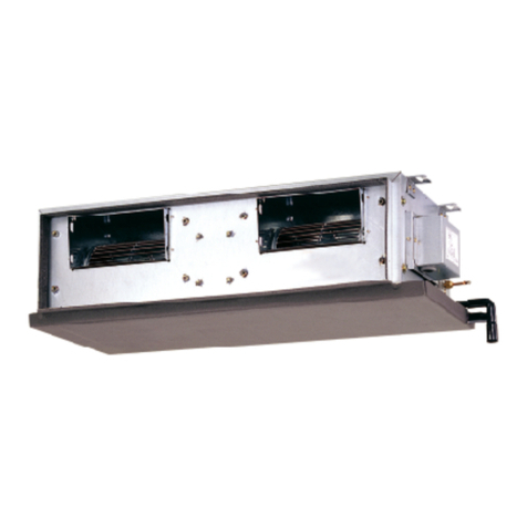
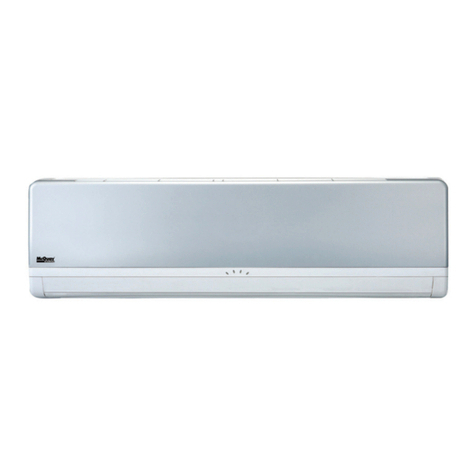
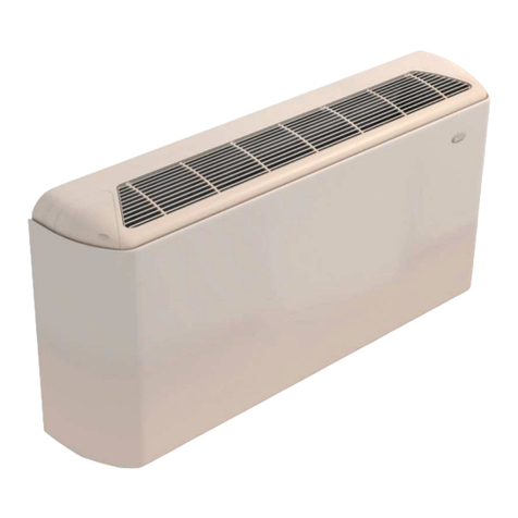
McQuay MFU-C User manual

PRODUCT MANUAL
PRODUCT MANUALPRODUCT MANUAL
PRODUCT MANUAL
FCF PM05D_ENG
Date: October 2005
Supersedes: FCF PM05C_ENG
Chilled Water Fan Coils
VERTICAL
Models: MFU-C MFU-H
MFC-C MFC-H

CHILLED WATER FAN COILS MF – McQuay FCF PM05D_ENG page 2/36
INDEX
INDEXINDEX
INDEX
Vertical Fan Coill page 3
General Characteristics page 4
Technical data page 7
Sound Level page 9
Operating Limits and Pressure drops page 11
Accessories page 12
Outlines and Dimensions page 14
Control Features page 16
- Mechanical controller AC page 16
- Electronic controller AC2800 (Optional) page 17
- Electronic thermostat AC8000 + Wireless Controllers AC5300 (Optional) page 18
- Mechanical ThermostatAC512/AC513 (Optional) page 19
Wiring Diagrams page 20
Technical Data at Conditions Non Standard page 27

CHILLED WATER FAN COILS MF – McQuay FCF PM05D_ENG page 3/36
VERTICAL FLOW FAN COIL
VERTICAL FLOW FAN COILVERTICAL FLOW FAN COIL
VERTICAL FLOW FAN COIL
THE NEW SHAPE OF WELNESS
The new series F of fan coil with vertical air flow is characterised by flexibility in performance and quiet
operation to offer a total wellness. It represents one of the most cost effective solutions to provide a
comfortable environment for both commercial and residential applications.
The series features 8 sizes, with cabinet for floor or wall installation and
chassis for concealed installations.
The units are available in the 2-pipes version with 3 or 4-rows coil –
nominal cooling capacity from 1.3 to 8.0kW; nominal heating capacity from
2.2 to 12.0kW – or in the 4-pipes version – nominal cooling capacity from
1.2 to 8.0kW; nominal heating capacity from 2.3 to 13.0kW.
The AC2800A electronic control (optional) allows, in its standard
configuration, both the regulation of all functionalities and units operating
modes and the connection into a network in Master & Slave configuration
up to 16 units.
The control module has been designed to automatically set up according to the unit configuration:
cooling or heating for 2-pipes application
cooling or heating for 2-pipes application with electrical heater
cooling or heating for 4-pipes application
with/without 2-way or 3-way ON/OFF regulating valves
activating all parameters and routines of regulation which optimise the operation of the unit.
Through AC2800A units can also be directly integrated with Smart Manager, McQuay solution for the
supervision of hydronic systems. With reference to Fan Coils, Smart Manager run up to 256 units and 120
zones.
NOMENCLATURE
U012MF
McQuay
Fan Coil type
F = Vertical Air Flow
Cooling Coil
0=3rows
4=4rows
Configuration
U= withCabinet
C = Concealed
C0
0 = without El.Heaters
Version
C = 2-pipes
H = 4-pipes
Size
Air Flow [CFM] x 10
U012MF
McQuay
Fan Coil type
F = Vertical Air Flow
Cooling Coil
0=3rows
4=4rows
Configuration
U= withCabinet
C = Concealed
C
0 = without El.Heaters
Version
C = 2-pipes
H = 4-pipes
Size
Air Flow [CFM] x 10
U012MF
McQuay
Fan Coil type
F = Vertical Air Flow
Cooling Coil
0=3rows
4=4rows
Configuration
U= withCabinet
C = Concealed
C0
0 = without El.Heaters
Version
C = 2-pipes
H = 4-pipes
Size
Air Flow [CFM] x 10
U012MF
McQuay
Fan Coil type
F = Vertical Air Flow
Cooling Coil
0=3rows
4=4rows
Configuration
U= withCabinet
C = Concealed
C
0 = without El.Heaters
Version
C = 2-pipes
H = 4-pipes
Size
Air Flow [CFM] x 10

CHILLED WATER FAN COILS MF – McQuay FCF PM05D_ENG page 4/36
GENERAL CHARACTERISTICS
Design
The design, elegant and considered in all details, harmonizes well with all types of interiors.
Cover, grids and cabinet materials have been selected with a special care to grant both the quality of the
finishing and the durability of the product.
Cover and grids are realized in ABS, RAL103; the cabinet is made of pre-painted sheet metal finished with
high quality paint, RAL1013.
Filter
The filter, located at the bottom of the unit, is easily accessible and self-locking, therefore no tools are
required for removing and re-assembling it.
The filter material grade is G1 and thanks to its pleated surface grants a filtration surface up to 60% greater
than traditional filters resulting in lower pressure drop and reduced noise emission.
Connections
Units are available with left hand water connections, which can be easily switched in the field if required.
Connections are equipped with air vents and drainage valves.
Controls
AC2800A Electronic control (optional)
Among the features of AC2800A control are:
Selectable temperature interval: 10-30°C or 16-30°C according to the application
Auto restart after power failure based on last temperature and mode setting
Timerwith2dailysettings(14weekly)
Change-over heat/cool, based on control system signal
Warm and cold draft protection
(this feature stops the fan when the set-point condition is satisfied and the water temperature is too warm
does not cause discomfort to the room occupants)
Antifreeze protection
(this function ensures that the room temperature is kept above a minimum level; if the unit is in off mode,
and the room temperature drops below 9°C, antifreeze protection is enabled and the unit temperature
rises above 11°C. At this point the unit is switched off again.)
Ambient temperature sensor incorrect operation
Air temperature sensor
(this is unit-mounted – if the control is wall-mounted, a second air sensor located in the control can be
used for fine tuning of the desired room temperature.)
Valves 2 or 3 ways with ON/OFF control
Smart manager integration
Besides the led present on the cover allow an immediate display of the unit operation status - fan speed,
operating mode, ON/OFF - and at the same time they are used with auto-diagnosis function.

CHILLED WATER FAN COILS MF – McQuay FCF PM05D_ENG page 5/36
GENERAL CHARACTERISTICS
The
AC2800A
control can be connected straight to Fan Coil Network, without any further components; in
fact the electronic board has integrated the NIM Module [ Network Interface Module].
The Network allows to control from a unique place al the operating parameters of the connected units.
The general control is executed through the Master unit and can be carry out through the electronic control
on board, the wall mounted installed thermostat or the infra-red handset.
Across AC2800A, the units can be connected straight to Smart Manager, the McQuay hydronic systems
supervision solution. With reference to hydronic units, Smart Manger manages until 256 units and 120
zones.
U
U
U
P
P
PT
T
TO
O
O2
2
25
5
56
6
6F
F
FA
A
AN
N
NC
C
CO
O
OI
I
IL
L
L
U
U
U
P
P
PT
T
TO
O
O5
5
50
0
0M
M
MI
I
IN
N
NI
I
IC
C
CH
H
HI
I
IL
L
LL
L
LE
E
ER
R
R

CHILLED WATER FAN COILS MF – McQuay FCF PM05D_ENG page 6/36
GENERAL CHARACTERISTICS
AC8000 Electronic thermostat
The thermostat AC8000 is predisposed for wall mounted and is composed of:
LCD DISPLAY: back-light and with graphic extremely easy, allows also an easy reading of the
operating parameters and auto-diagnosis
KEYBOARD: allows to set parameters as: room temperature, fan speed, manual or automatic fan
speed setting, operating mode summer/winter, ON/OFF, operating time setting
INFRA-RED HANDSET AC5300: standard, assures an utilization more easy than other thermostat
2.5 metres.
AC512 Mechanical thermostat
[for 2 pipes versions] and
Mechanical thermostat AC513
[for 4 pipes
versions]
Easy utilization, allows to set essential operating parameter: room temperature, fan speed, ON/OFF
ACCESSORIES
Valves kit [standard condensate drain panel ], 2 or 3 ways
Controls
Feet (cover and/or support)
Frontal air intake module
UNIT CONFIGURATION
1MF McQuay Vertical Fan Coil
3UWith cabinet
Cconcealed
403-row cooling coil
44-row cooling coil
5xx capacity size [CFM x 10]
7C2-pipes
H4-pipes
80no electric heater
9Lleft side water connections
Rright side water connections
10 Bpower supply: 220-240V/1ph/50Hz
11 CN without on-board control*
CM with electronic AC2800B on-board control**
CE with electronic AC2800A on-board control***
12 EExport
Note
*
standard for concealed units
**
standard for units with cabinet; not applicable to concealed units
***
not applicable to concealed units

CHILLED WATER FAN COILS MF – McQuay FCF PM05D_ENG page 7/36
TECHNICAL DATA
2PIPES 3ROWS
MODELS 012C 020C 025C 035C 050C 060C 080C 090C
Nominal Air Flow
(High/Medium/Low) m
3
/h 290/245/
197
380/296/
210
497/349/
260
705/565/
400
853/695/
465
1141/969/
705
1360/
1063/82
4
1500
/1368/
1190
Available Static Pressure Pa -- -- -- -- -- -- -- --
Total Cooling Capacity
1
kW 1.3 1.8 2.7 3.6 4.8 5.9 6.9 8.0
Total Sensible Capacity
1
kW 1.0 1.5 1.9 2.6 3.6 4.6 5.3 5.8
Heating Capacity
2
kW 2.2 2.7 3.6 4.8 6.2 8.1 10.5 12.0
Water Flow Rate l/s 0.063 0.085 0.129 0.170 0.227 0.282 0.358 0.347
Water Pressure Drop - Cooling kPa 4 5 10 16 28 33 18 20
Lp (Sound Pressure Level)
3
dB(A) 38/35/33 42/37/32 42/35/32 48/44/39 47/39/31 53/48/41 51/47/41 53/51/47
Power Supply V/ph/Hz 220~240/1/50
Fan N°. n° 1 1 2 2 2 2 33
Max Power Supply
4
kW 0.024 0.044 0.044 0.059 0.068 0.102 0.147 0.167
Cond. Drain Connections mm 20 20 20 20 20 20 20 20
Water Connections inches 3/4" 3/4" 3/4" 3/4" 3/4" 3/4" 3/4" 3/4"
Total volume litres 0.792 1.158 1.525 1.89
Weight [with package] kg 20 [22] 24 [27] 26 [30] 35 [39]
Weight with cabinet
[with package] kg 22 [25] 29 [32] 32 [37] 45 [50]
Dimens. unit (WxHxD) mm 704x540x224 904x540x224 1104x540x224 1304x540x224
Dimens. with cabinet (WxHxD) mm 910x539x230
1110x539
x230
1310x539x230 1510x539x230
2PIPES 4ROWS
MODELS 412C 420C 425C 435C 450C 460C 480C 490C
Nominal Air Flow
(High/Medium/Low) m
3
/h 254/215/
176
369/321/
240
445/330/
250
677/545/
380
811/663/
456
1068/915/
672
1300/
1165/
908
1450/
1288/
1120
Available Static Pressure Pa -- -- -- -- -- -- -- --
Total Cooling Capacity
1
kW 1.5 2.7 3.1 4.6 5.3 6.4 7.1 8.3
Total Sensible Capacity
1
kW 1.1 1.7 2.1 2.8 3.7 5.0 5.5 5.8
Heating Capacity
2
kW 2.3 2.8 4.2 5.3 6.8 8.4 11.0 12.5
Water Flow Rate l/s 0.073 0.098 0.149 0.193 0.251 0.304 0.397 0.409
Water Pressure Drop - Cooling kPa 4 5 10 14 21 20 18 17
Lp (Sound Pressure Level)
3
dB(A) 38/36/33 42/37/32 41/34/32 47/43/38 47/39/31 53/48/41 51/47/41 53/50/47
Power Supply V/ph/Hz 220~240/1/50
Fan N°. n° 1 1 2 2 2 2 33
Max Power Supply
4
kW 0.021 0.050 0.051 0.056 0.077 0.107 0.143 0.167
Cond. Drain Connections mm 20 20 20 20 20 20 20 20
Water Connections inches 3/4" 3/4" 3/4" 3/4" 3/4" 3/4" 3/4" 3/4"
Total volume litres 1.056 1.545 2.033 2.52
Weight [with package] kg 24 [26] 28 [30] 30 [33] 35 [39]
Weight with cabinet
[with package] kg 26 [27] 31 [35] 35 [40] 45 [50]
Dimens. unit (WxHxD) mm 704x540x224 904x540x224 1104x540x224 1304x540x224
Dimens. with cabinet (WxHxD) mm 910x539x230 1110x539x230 1310x539x230 1510x539x230
NOTES
1 At the following nominal conditions: nominal air flow; 7/12°C inlet/outlet water temperature; 27°C db/19°C wb inlet air temperature; High speed
2 At the following nominal conditions: nominal air flow 50°C inlet water temperature; 20°C inlet air temperature; same water flow as for cooling; High speed
3 At High/Medium/Low speed; nominal air flow; measured in a room of 100mvolume and 0.5 sec. reverberation time ( e.g. office/conference room with carpet on the floor)
4 Nominal Air Flow; High Fan Speed

CHILLED WATER FAN COILS MF – McQuay FCF PM05D_ENG page 8/36
TECHNICAL DATA
4PIPES 3+1ROWS
MODELLI 012H 020H 025H 035H 050H 060H 080H 090H
Nominal Air Flow
(High/Medium/Low) m
3
/h 254/215/
176
369/321/
240
445/330/
250
677/545/
380
811/663/
456
1068/915/
672
1300/
1063/
824
1450/
1248/
1078
Available Static Pressure Pa -- -- -- -- -- -- -- --
Total Cooling Capacity
5
kW 1.2 1.8 2.5 3.5 4.6 5.7 6.9 8.0
Total Sensible Capacity
5
kW 0.9 1.4 1.7 2.5 3.4 4.4 4.9 5.2
Water Flow Rate l/s 0.057 0.084 0.118 0.165 0.219 0.271 0.32 0.345
WaterPressureDrop-Cooling kPa 4 5 8 15 26 16 15 17
Heating Capacity
6
kW 2.3 2.9 4.3 5.6 7.0 8.6 12.0 13.0
Water Flow Rate l/s 0.057 0.071 0.104 0.137 0.172 0.209 0.216 0.339
Water Pressure Drop - Heating kPa 11 18 30 18 35 40 24 14
Lp (Sound Pressure Level)
7
dB(A) 38/35/32 42/37/32 41/34/31 47/43/38 47/39/31 53/48/41 51/47/41 53/50/47
Power Supply V/ph/Hz 220~240/1/50
Fan N°. n° 1 1 2 2 2 2 33
Max Power Supply
4
kW 0.021 0.050 0.051 0.056 0.077 0.107 0.140 0.161
Cond. Drain Connections mm 20 20 20 20 20 20 20 20
Water Connections inches 3/4" 3/4" 3/4" 3/4" 3/4" 3/4" 3/4" 3/4"
Total volume litres [0.792 + 0.264] [1.158 + 0.386] [1.525 + 0.508] [1.89 + 0.63]
Weight [with package] kg 24 [26] 28 [30] 30 [33] 35 [39]
Weight with cabinet [with
package] kg 26 [27] 31 [35] 35 [40] 45 [50]
Dimens. unit (WxHxD) mm 704x540x224 904x540x224 1104x540x224 1304x540x224
Dimens. with cabinet (WxHxD) mm 910x539x230 1110x539x230 1310x539x230 1510x539x230
NOTES
4 Nominal Air Flow; High Fan Speed
5 At the following nominal conditions: nominal air flow; 7/12°C inlet/outlet water temperature; 27°C db / 19°C wb inlet air temperature; High speed
6 At the following nominal conditions: nominal air flow; 70/60 °C inlet/outlet water temperature; 20°C inlet air temperature; High speed
7 At High/Medium/Low speed; nominal air flow; measured in a room of 100 mvolume and 0.5 sec. reverberation time ( e.g. office/conference room with carpet on the floor)

CHILLED WATER FAN COILS MF – McQuay FCF PM05D_ENG page 9/36
SOUND LEVEL
2 PIPES 3ROWS
2 PIPES 4ROWS
Sound pressure level and NR are measured to a room of 100 m volume and 0.5 sec. reverberation time ( e.g.
office/conference room with carpet on the floor).
63Hz 125Hz 250Hz 500Hz 1kHz 2kHz 4kHz 8kHz
High
49,3 49,3 47,1 42,1 37,0 30,6 24,0 22,9 46,0 38,0 33,0
Medium
46,9 46,9 44,2 38,9 32,6 25,6 20,3 22,2 43,5 35,5 30,0
Low
51,7 51,7 52,1 49,0 44,8 39,0 31,2 26,2 40,5 32,5 28,0
High
48,5 48,5 47,6 44,3 38,5 30,7 23,3 24,3 50,0 42,0 37,0
Medium
45,0 45,0 43,0 38,7 31,9 23,7 19,0 22,5 44,5 36,5 32,0
Low
50,3 50,3 50,7 47,6 43,4 37,6 29,8 24,8 40,0 32,0 28,0
High
51,4 51,4 52,0 48,1 44,4 38,6 31,5 26,0 50,0 42,0 37,0
Medium
46,9 46,9 46,1 42,4 36,9 29,2 21,8 22,7 43,0 35,0 31,0
Low
45,4 45,4 43,6 39,1 32,6 24,5 19,2 22,6 40,0 32,0 28,0
High
57,1 57,1 57,3 53,3 50,2 45,8 39,4 33,0 55,5 47,5 43,0
Medium
53,2 53,2 53,7 50,0 46,2 41,2 33,8 27,8 51,5 43,5 39,0
Low
48,9 48,9 49,2 45,6 40,7 34,4 26,0 23,6 47,0 38,5 34,0
High
54,7 54,7 55,6 53,2 50,8 45,0 38,7 31,2 55,0 47,0 43,0
Medium
48,7 48,7 48,1 45,9 41,4 34,0 26,4 23,8 47,0 39,0 35,0
Low
47,8 47,8 41,6 37,5 30,1 21,7 19,5 23,1 39,0 31,0 26,0
High
60,4 60,4 60,5 58,2 57,1 52,2 47,2 40,5 61,0 53,0 51,0
Medium
56,1 56,1 55,4 53,3 51,8 46,4 40,7 33,7 56,0 48,0 44,0
Low
53,2 53,2 49,5 47,6 44,6 38,1 31,8 26,8 49,0 41,5 38,0
High
17,6 27,8 41,9 44,7 46,3 45,6 39,5 33,6 43,0 51,0 47,0
Medium
15,9 24,6 38,3 41,4 42,6 41,2 34,4 27,7 39,5 47,0 42,0
Low
13,6 19,5 32,8 35,4 35,8 33,2 25,2 18,2 33,0 41,0 37,0
High
17,6 29,5 43,9 46,3 48,2 47,6 41,6 36,6 45,0 53,0 48,0
Medium
16,2 27,2 41,1 44,1 45,7 44,9 38,4 33,1 42,5 51,0 46,0
Low
16,0 24,3 38,1 41,2 42,2 40,7 33,9 28,0 39,0 47,0 42,0
025C
Lp
[dB(A)]
1/1 Octave Sound pressure level Lw
[dB(A)]
Model Speed
012C
020C
090C
060C
080C
035C
050C
NR
63Hz 125Hz 250Hz 500Hz 1kHz 2kHz 4kHz 8kHz
High
50,3 50,3 48,8 43,9 39,2 34,3 27,2 23,4 46,0 38,0 33,0
Medium
48,9 48,9 46,7 41,7 36,6 30,2 23,6 22,5 43,5 35,5 30,0
Low
46,9 46,9 44,2 38,9 32,6 25,6 20,3 22,2 40,5 32,5 27,0
High
51,5 51,5 51,9 48,8 44,6 38,8 31,0 26,0 50,0 42,0 38,0
Medium
48,7 48,7 47,8 44,5 38,7 30,9 23,5 24,5 45,0 37,0 33,0
Low
45,7 45,7 43,7 39,4 32,6 24,4 19,7 23,2 40,5 32,5 28,0
High
50,7 50,7 51,1 48,0 43,8 38,0 30,2 25,2 49,0 41,0 37,0
Medium
46,2 46,2 45,3 42,0 36,2 28,4 21,0 22,0 43,0 34,5 31,0
Low
45,0 45,0 43,0 38,7 31,9 23,7 19,0 22,5 39,5 31,5 27,0
High
56,5 56,5 57,3 52,8 49,5 44,8 38,4 32,1 55,0 47,0 42,0
Medium
52,9 52,9 53,7 49,5 45,5 40,2 33,0 27,3 51,5 43,0 38,0
Low
48,7 48,7 49,0 45,2 40,2 33,6 25,7 24,1 46,0 38,0 34,0
High
54,7 54,7 55,6 53,2 50,8 45,0 38,7 31,2 55,0 47,0 43,0
Medium
48,7 48,7 48,1 45,9 41,4 34,0 26,4 23,8 47,0 39,0 35,0
Low
48,1 48,1 41,9 37,8 30,4 22,0 19,8 23,4 39,0 31,0 26,0
High
60,4 60,4 60,5 58,2 57,1 52,2 47,2 40,5 61,0 53,0 51,0
Medium
56,1 56,1 55,4 53,3 51,8 46,4 40,7 33,7 56,0 48,0 44,0
Low
53,2 53,2 49,5 47,6 44,6 38,1 31,8 26,8 49,0 41,5 38,0
High
19,2 27,6 41,6 44,8 46,2 45,1 39,0 33,9 43,0 51,0 46,0
Medium
18,6 24,5 37,9 41,7 42,2 40,7 34,1 28,3 39,0 47,0 42,0
Low
14,8 19,6 32,3 35,6 35,6 32,9 25,3 18,9 35,5 40,5 36,0
High
19,6 28,8 43,4 45,7 47,7 46,8 40,8 35,4 44,5 52,5 47,0
Medium
18,9 26,9 40,7 43,6 45,3 44,1 37,8 31,8 42,0 50,0 45,0
Low
16,8 24,5 37,7 40,9 41,9 40,3 33,5 27,1 39,0 47,0 42,0
450C
460C
480C
490C
412C
420C
425C
435C
Model Speed 1/1 Octave Sound pressure level Lw
[dB(A)]
Lp
[dB(A)] NR

CHILLED WATER FAN COILS MF – McQuay FCF PM05D_ENG page 10/36
SOUND LEVEL
4PIPES 3+1ROWS
Sound pressure level and NR are measured to a room of 100 m volume and 0.5 sec. reverberation time ( e.g.
office/conference room with carpet on the floor).
63Hz 125Hz 250Hz 500Hz 1kHz 2kHz 4kHz 8kHz
High
50,3 50,3 48,8 43,9 39,2 34,3 27,2 23,4 46,0 38,0 33,0
Medium
48,9 48,9 46,7 41,7 36,6 30,2 23,6 22,5 43,5 35,5 30,0
Low
46,9 46,9 44,2 38,9 32,6 25,6 20,3 22,2 40,5 32,5 27,0
High
51,5 51,5 51,9 48,8 44,6 38,8 31,0 26,0 50,0 42,0 38,0
Medium
48,7 48,7 47,8 44,5 38,7 30,9 23,5 24,5 45,0 37,0 33,0
Low
45,7 45,7 43,7 39,4 32,6 24,4 19,7 23,2 40,5 32,5 28,0
High
50,7 50,7 51,1 48,0 43,8 38,0 30,2 25,2 49,0 41,0 37,0
Medium
46,2 46,2 45,3 42,0 36,2 28,4 21,0 22,0 43,0 34,5 31,0
Low
45,0 45,0 43,0 38,7 31,9 23,7 19,0 22,5 39,5 31,5 27,0
High
56,5 56,5 57,3 52,8 49,5 44,8 38,4 32,1 55,0 47,0 42,0
Medium
52,9 52,9 53,7 49,5 45,5 40,2 33,0 27,3 51,0 43,0 38,0
Low
48,7 48,7 49,0 45,2 40,2 33,6 25,7 24,1 46,0 38,0 34,0
High
54,7 54,7 55,6 53,2 50,8 45,0 38,7 31,2 55,0 47,0 43,0
Medium
48,7 48,7 48,1 45,9 41,4 34,0 26,4 23,8 47,0 39,0 35,0
Low
48,1 48,1 41,9 37,8 30,4 22,0 19,8 23,4 39,0 31,0 26,0
High
60,4 60,4 60,5 58,2 57,1 52,2 47,2 40,5 61,0 53,0 51,0
Medium
56,1 56,1 55,4 53,3 51,8 46,4 40,7 33,7 56,0 48,0 44,0
Low
53,2 53,2 49,5 47,6 44,6 38,1 31,8 26,8 49,0 41,5 38,0
High
19,2 27,6 41,6 44,8 46,2 45,1 39,0 33,9 43,0 51,0 46,0
Medium
18,6 24,5 37,9 41,7 42,2 40,7 34,1 28,3 39,0 47,0 42,0
Low
14,8 19,6 32,3 35,6 35,6 32,9 25,3 18,9 32,5 40,5 36,0
High
19,6 28,8 43,4 45,7 47,7 46,8 40,8 35,4 44,5 52,5 47,0
Medium
18,9 26,9 40,7 43,6 45,3 44,1 37,8 31,8 42,0 50,0 45,0
Low
16,8 24,5 37,7 40,9 41,9 40,3 33,5 27,1 39,0 47,0 42,0
090H
050H
060H
Speed
080H
025H
035H
020H
Model Lw
[dB(A)]
012H
1/1 Octave Sound pressure level Lp
[dB(A)] NR

CHILLED WATER FAN COILS MF – McQuay FCF PM05D_ENG page 11/36
OPERATING LIMITS AND PRESSURE DROPS
OPERATING LIMITS MFU / MFC
Water Circuit
Maximum water-side pressure
Minimum entering water temperature
Maximum entering water temperature
16.4 kg/cm
2
3°C (cooling)
80°C (heating)
Room air
Minimum temperature
Maximum temperature
16°C (cooling), 10°C (heating)
36°C (cooling), 30°C (heating)
Power supply
Nominal single-phase voltage
Operating voltage limits
Connections
220~240 V / 50 Hz
± 10% Volt / ± 2Hz
AWG18 (or 1mm
2
)
PRESSURE DROPS
*The pressure drop is for coil only and excludes water connections and valves.
! # $ & ( * + , . 0 * 1 2 3
! # $ & ( * + , . 0 * 1 2 3 ! # $ & ( * + , . 0 * 1 2 3
! # $ & ( * + , . 0 * 1 2 3
4 56
7
7
8
56
9
5:
;
<
= >
4 ?
@
4 56
7
7
8
56
9
5:
;
<
= >
4 ?
@
4 56
7
7
8
56
9
5:
;
<
= >
4 ?
@
4 56
7
7
8
56
9
5:
;
<
= >
4 ?
@
012/020
025/035
050/060
080/090
Water Flow* [l/s]
Pressure Drop* [k/Pa]
2 PIPES / 3 ROWS
! # $ & ( * + , . 0 * 1 2 3
! # $ & ( * + , . 0 * 1 2 3 ! # $ & ( * + , . 0 * 1 2 3
! # $ & ( * + , . 0 * 1 2 3
4 56
7
7
8
56
9
5:
;
<
= >
4 ?
@
4 56
7
7
8
56
9
5:
;
<
= >
4 ?
@
4 56
7
7
8
56
9
5:
;
<
= >
4 ?
@
4 56
7
7
8
56
9
5:
;
<
= >
4 ?
@
012/020
025/035
050/060
080/090
Water Flow* [l/s]
Pressure Drop* [k/Pa]
2 PIPES / 3 ROWS
A C D C E G H I J L N G
A C D C E G H I J L N GA C D C E G H I J L N G
A C D C E G H I J L N G
P
Q P
S P
T P
U P
V P P
V Q P
V S P
V T P
V U P
Q P P
P W V P W Q P W Z P W S P W \ P W T P W ^ P W U P W _
` b d e f g i j k l m i n o p
` b d e f g i j k l m i n o p` b d e f g i j k l m i n o p
` b d e f g i j k l m i n o p
q r s
t
t
u
rs
v
rw
x
y
z {
q |
}
q r s
t
t
u
rs
v
rw
x
y
z {
q |
}
q r s
t
t
u
rs
v
rw
x
y
z {
q |
}
q r s
t
t
u
rs
v
rw
x
y
z {
q |
}
412/420
425/435
450/460
480/490
Water Flow* [l/s]
Pressure Drop* [k/Pa]
2 PIPES / 4 ROWS
A C D C E G H I J L N G
A C D C E G H I J L N GA C D C E G H I J L N G
A C D C E G H I J L N G
P
Q P
S P
T P
U P
V P P
V Q P
V S P
V T P
V U P
Q P P
P W V P W Q P W Z P W S P W \ P W T P W ^ P W U P W _
` b d e f g i j k l m i n o p
` b d e f g i j k l m i n o p` b d e f g i j k l m i n o p
` b d e f g i j k l m i n o p
q r s
t
t
u
rs
v
rw
x
y
z {
q |
}
q r s
t
t
u
rs
v
rw
x
y
z {
q |
}
q r s
t
t
u
rs
v
rw
x
y
z {
q |
}
q r s
t
t
u
rs
v
rw
x
y
z {
q |
}
412/420
425/435
450/460
480/490
Water Flow* [l/s]
Pressure Drop* [k/Pa]
2 PIPES / 4 ROWS

CHILLED WATER FAN COILS MF – McQuay FCF PM05D_ENG page 12/36
ACCESSORIES
VALVE KITS
MF – C [2 - PIPES]
The kit includes:
2-way regulating valve; diameter ¾”
thermoelectric actuator 230 vca
copper pipes Ø 18 with welded connections ¾” GAS, Niples type
fittings
Note: To avoid any drain leakage insulate water connections on board.

CHILLED WATER FAN COILS MF – McQuay FCF PM05D_ENG page 13/36
ACCESSORIES
MF – H [4 – PIPES]
The kit includes:
2-way/4-port regulating valve; diameter ¾”
thermoelectric actuator 230 vca
copper pipes Ø 18 with welded connections ¾” GAS, Niples type
fittings
Note: To avoid any drain leakage insulate water connections on board.

CHILLED WATER FAN COILS MF – McQuay FCF PM05D_ENG page 14/36
ACCESSORIES
MF – H [4 – PIPES]
The kit includes:
1. Primary circuit
3-way/4-port regulating valve; diameter ¾”
thermoelectric actuator 230 vca
copper pipes Ø 18 with welded connections ¾” GAS, Niples type
fittings
2. Auxiliary circuit
3-way/4-port regulating valve; diameter 1/2”
thermoelectric actuator 230 vca
copper pipes Ø 14 with welded connections ¾” GAS, Niples type
fittings
Note: To avoid any drain leakage insulate water connections on board.

CHILLED WATER FAN COILS MF – McQuay FCF PM05D_ENG page 15/36
ACCESSORIES
Watts-Cazzaniga Valves features
Valves 3-way Valves 2-way Actuator
- Deviation and/or Mixing - Intercepting - ON-OFF
- PN 16bar - PN 16bar - NC pre-set
- 140N
- Power Supply 230Vca
Installation Example for valves 3- way, 4 pipes.
Thanks to the special configuration of the plug controlling the by-pass flow, the 3-way with 4 ports valves can
be used equally as well as diverting and mixing valves.
DEVIATING
MIXING

CHILLED WATER FAN COILS MF – McQuay FCF PM05D_ENG page 16/36
OUTLINES AND DIMENSIONS
MFC – C/H
012 / 020
412 / 420
025 / 035
425 / 435
050 / 060
450 / 460
080 / 090
480 /490
A
598 798 998 1198
B
568 768 968 1168
C
526 726 926 1126
D
407 607 807 1007
E
704 904 1104 1304
F
529 729 929 1129
A
B
C
E
F
D
A
B
C
E
F
D
FIXING SLOTS
WLWCTRIC BOX
FILTER
FIXING SLOTS
FIXING SLOTS
WATER INLET
(HEATING)
WATER INLET
COLLAR
WATER OUTLET
(HEATING)
WATER OUTLET
CONDENSATE DRAIN PAN
(CONNECTIONS AND
VALVES)
FIXING SLOTS
WLWCTRIC BOX
FILTER
FIXING SLOTS
FIXING SLOTS
FIXING SLOTS
WLWCTRIC BOX
FILTER
FIXING SLOTS
FIXING SLOTS
WATER INLET
(HEATING)
WATER INLET
COLLAR
WATER OUTLET
(HEATING)
WATER OUTLET
CONDENSATE DRAIN PAN
(CONNECTIONS AND
VALVES)
WATER INLET
(HEATING)
WATER INLET
COLLAR
WATER OUTLET
(HEATING)
WATER OUTLET
CONDENSATE DRAIN PAN
(CONNECTIONS AND
VALVES)

CHILLED WATER FAN COILS MF – McQuay FCF PM05D_ENG page 17/36
OUTLINES AND DIMENSIONS
MFU – C/H
012 / 020
412 / 420
025 / 035
425 / 435
050 / 060
450 / 460
080 / 090
480 /490
A
910 1110 1310 1510
Height = 100 mm from the wall for:
- Feet ( cover and/or support)
- Frontal air intake module
538.6
A
490
48.6
165
65
230

CHILLED WATER FAN COILS MF – McQuay FCF PM05D_ENG page 18/36
CONTROL FEATURES
ELECTRONIC CONTROL AC2800B
Location On Board
Models Standard for MFU series, all versions
Parameters On / Off
Temperature
Fan Speed
Operation Mode
Main Functions Selectable Temperature operation range:
10-30°C
Warm and cold draft protection
Valves 2 or 3 ways with ON/OFF control
Integration into FCU Network ---
Integration with Smart Manager ---
1
Potentiometer for temperature regulation
2
On/Off keys
3
On/Off led
4
Heating / Cooling mode keys
5
Heating / Cooling mode led
6
Fan Speed selection keys
7
Fan Speed led (HIGH)
8
Fan Speed led (MEDIUM)
9
Fan Speed led (LOW)
5
6
4
321
7
8
9
5
6
4
321
7
8
9

CHILLED WATER FAN COILS MF – McQuay FCF PM05D_ENG page 19/36
CONTROL FEATURES
ELECTRONIC CONTROL AC2800A (OPTIONAL)
Location On Board
Models MFU series, all versions
Parameters On / Off
Temperature
Fan Speed
Automatic Fan Speed selection
Operation Mode
Main Functions Selectable Temperature operation range:
10-30°C or 16-30°C
Automatic re-start with memory settings
Heating/Cooling change-over based on system control input
Auto - diagnosis
Warm and cold draft protection
Antifreeze protection
Air sensor control
Valves 2 or 3 ways with ON/OFF control
Integration into FCU Network Direct Connection
Integration with Smart Manager Direct Connection
1
Potentiometer for temperature regulation
2
On/Off keys
3
On/Off led
4
Heating / Cooling mode keys
5
Heating / Cooling mode led
6
Fan Speed selection keys
7
Fan Speed led (HIGH)
8
Fan Speed led (MEDIUM)
9
Fan Speed led (LOW)
AUTO-DIAGNOSIS
Led Blinking
7
: Ambient temperature sensor incorrect operation
Led Blinking
8
: Water temperature sensor incorrect operation
Led Blinking
9
: Potentiometer incorrect operation or on board control/wall mounted thermostat conflicting
mode selection
Led Blinking
5
: Fan Coil / Chiller conflicting mode selection
5
6
4
321
7
8
9
5
6
4
321
7
8
9

CHILLED WATER FAN COILS MF – McQuay FCF PM05D_ENG page 20/36
CONTROL FEATURES
ELECTRONIC THERMOSTAT AC8000 + REMOTE CONTROL AC5300 (OPTIONAL)
Location Wall Mounted
Models All models; all versions
Parameters On/Off
Temperature
Fan Speed
Auto Fan Speed selection
Date / Time setting
Mode
Main Functions Selectable Temperature operation range:
10-30°C or 16-30°C
Automatic re-start with memory settings
Heating/Cooling change-over based on system control input
Auto-diagnosis
Timer with 2 daily setting (14 weekly)
Warm and cold draft protection
Antifreeze protection
Airsensorcontrol
Valves 2 or 3 ways with ON/OFF control
Remote control – max. distance: 2.5 metres
Integration into FCU Network Connection through AC2800 control
Direct connection [integrated NIM]
Integration with Smart Manager Connection through AC2800 control
Direct connection [integrated NIM]
1
On/Off key
2
Heating/Cooling mode key
3
Clock/Timer setting
4
Fan Speed selection key (HIGH/MEDIUM/LOW)
5
Temperature up key
6
Temperature down key
7
Back-light LCD Display
a
On/Off key
b
Fan Speed selection key (HIGH/MEDIUM/LOW)
c
Temperature up key
d
Temperature down key
e
Heating/Cooling mode key
f
Clock/Timer setting
AUTO-DIAGNOSIS
E1
:Ambient temperature sensor incorrect operation
E2
:Water temperature sensor incorrect operation
E3
:Potentiometer incorrect operation or on board control/wall mounted thermostat conflicting mode selection
E4
:Fan Coil / Chiller conflicting mode selection
a
b
cd
e
f
a
b
cd
e
f
123456
7
123456
123456
7
Other manuals for MFU-C
1
This manual suits for next models
3
Table of contents
Other McQuay Fan manuals