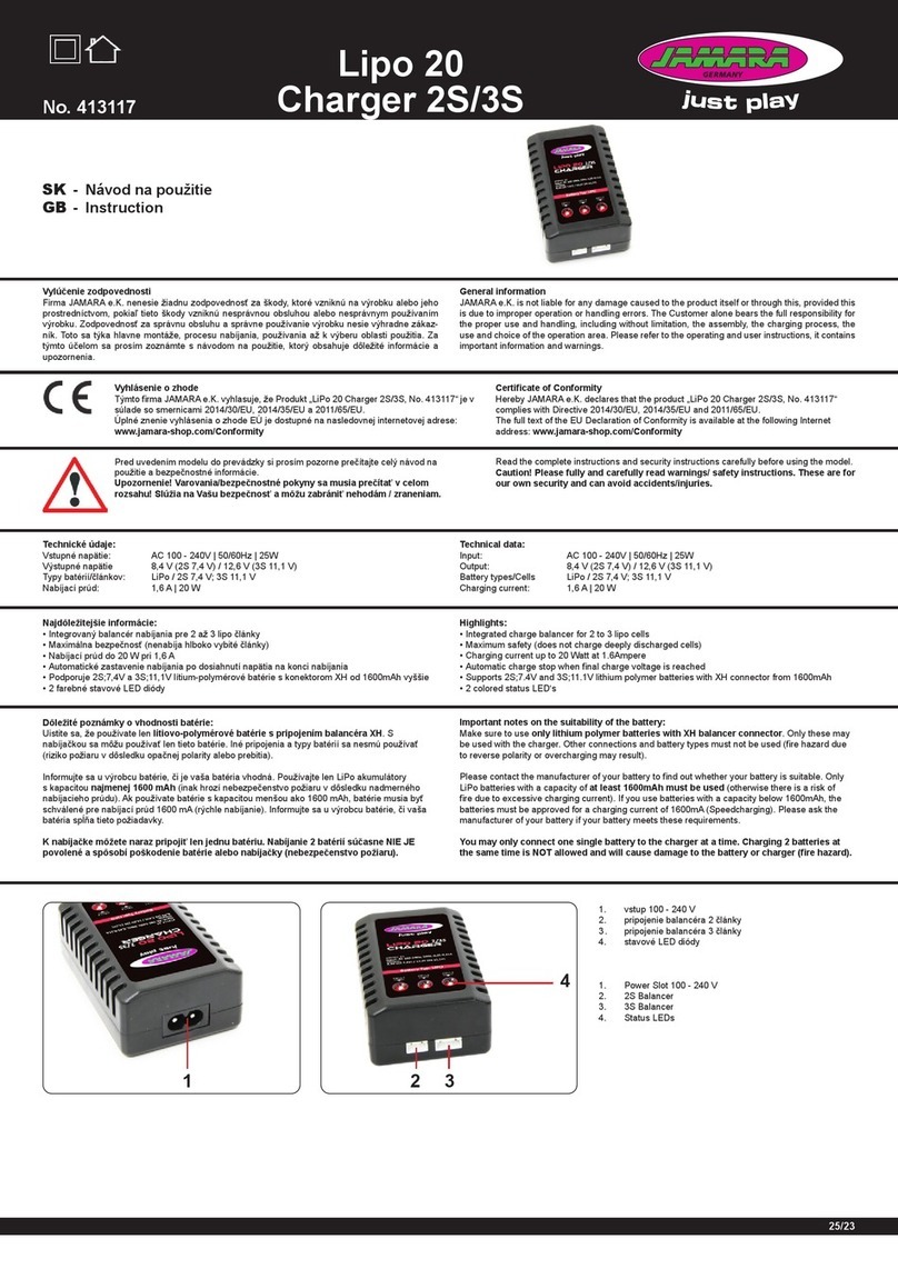
Meanwell NPB Series User manual

NPB & NPP Series
Installation Manual
High Reliable Intelligent Battery Charger
Intelligent Battery Charger

The NPB and NPP series are MEAN WELL s new generation of high-power'
density smart chargers. The NPB-120/240/360 series adopt a high
efficiency hardware design, allowing the products to operate both
efficiently and stably. The NPB-450/450NFC/750/1200/1700 series are
fully digital designed products and feature the benefits of
miniaturization, high efficiency and intelligence. Being a high efficiency
hardware and microprocessor power management design, with four
charge curve selection (one programmable and three embedded) and the
world's first invention: auto ranging charge, the chargers have the ability
to cope with various batteries from different brands, such as lead-acid
batteries (flooded, gel and AGM) and li-ion (lithium iron, lithium
manganese), which some may require special charge treatment. Users
also can adjust and modify charge parameters (charge voltage/current,
cut-off voltage/current...etc.) in each charge stage via the built-in CAN
bus interface, some battery protection functions, in addition, may be
disabled through the intelligent communication interface. The whole NPP
family is equipped with both charger and power supply modes. These two
modes can be set freely according to user s demand. In the charger mode,'
a three-stage charging function is provided, and the charging voltage and
current can be adjusted according to different batteries. If it s in the'
power supply mode, it will be able to driver loads. The flexible andgeneral
intelligent design of the NPB and NPP series can provide a perfect
solution for complex battery applications.

Index
2024 02 Ver 7.2024 02 Ver 7.
1.Safety Guidelines
2.Introduction
21. Model number
2.2 Features
23. Main specification
24. Safety overview
25. Derating curve
26. Mechanical specification
3.Installation & Wiring
3.1 Precautions
32. Installation procedures
3.3 Cable selection
3.4 Battery selection
3.5 Serial and parallel
connection of battery
4.User Interface Panel
4.1 Panel description
42. LED indicator
43. Pin assignment of (NPB)
44. Pin assignment of
(NPB- )450NFC
45. Pin assignment of (NPP)
5.Explanation of setting
5.1 Function difference
5.2 Function description
. Operating modes53
(2/3 stage)
5.4 Setting of charging curve
5.5 Back to factory setting
6.CAN usBProtocol
61.CANBus specifications
6.2 CAN usBaddress setting
6.3 CANBus commend list
64. Communication Examples
65. CANBus value range and
tolerance
7.NPB-450-XXNFC APP
Operation Instruction
71. Before usage
7.2 Compatibility
7.3 How to use
7.4 APP Function Description
7.5 NFC Operating Attention
7.6 APP Frequently Asked
Question
8.Protections and failure
correction
81. Protections
8.2 Failure correction
9.Warranty
1
2
2
2
3
19
20
21
24
24
24
25
25
26
27
27
30
31
32
33
34
34
34
38
41
44
45
45
46
47
53
60
65
65
65
65
66
68
68
69
69
70
71

1
nIt is suitable for lead-acid batteries (flooded water type, el colloid type,g
AGM adsorption glass fiber) or (lithium iron, lithium manganese, lithium
ternary…etc.)
nThe charger must be installed in a dry and well ventilated area. It should
not be exposed to rain or snow.
nAll failures should be examed by the qualified technician.
nThe cables between charger and battery should be kept as short as
possible to prevent excessive voltage drop (suggested cable length:
50cm~100cm). Too much voltage drop will lead to longer charging period.
nMake sure charging voltage and current meet battery's specification.
nRefrain from connecting new and old batteries in series.
nCharger should be in the OFF mode before making battery connection or
disconnection.
nFor auto ranging. Please refer to the manual before using this function.
And note that, it must work together with battery that built-in BMS.
nThis equipment is not suitable for use in locations where children are likely
to be present.
nThe protective earthing is used as a safeguard, the instructions shall
require connection of the equipment protective earthing conductor to the
installation protective earthing conductor (for example, by means of a
power cord connected to a socket-outlet with earthing connection).
1 Safety Guidelines.
1
nIndoor use only.
2
2
2 Introduction.
2.1 Model number
Serial name (NPB, NPP)
Rated power (120W~1700W)
DC output voltage
(12: 14.4Vdc, 24: 28.8Vdc, 48: 57.6Vdc, 72: 72Vdc)
24NPB --120
lIt is suitable for lead-acid batteries and lithium iron batteries
l2 or 3-stage charging curve by DIP S.W.
l4 charging curve ready to uses
( 450NFC/only for NPB-450/ 750/1200/1700)
lBuilt-in active PFC function
lBuilt-in CANbus protocol for control and monitoring
(Only for NPB-450/ 750/1200/1700)450NFC/
lProtections: Short circuit/Over voltage/Over temperature/Battery
under voltage and over voltage/Battery reverse polarity)
lAuto ranging function (Only for NPB-450/ 750/1200/1700)450NFC/
lBoth charger mode or power supply can be chose accordinglyn
lLED indicator: status/ abnormal indication
lDEKRA/UL/EAC/CE/ certifUKCA ied
l3 year warrantys
2.2 Features
NFC
NFC: Built in NFC Introduction
{
Blank Non Introduction: -NFC

3
2.3 Specification
2
NPB-120 series
INPUT
MODEL
BOOST CHARGE VOLTAGE
(Vboost)(default)
FLOAT CHARGE VOLTAGE
(Vfloat)(default)
RECOMMENDED BATTERY
CAPACITY (AMP HOURS)
VOLTAGE ADJUSTABLE RANGE
OUTPUT CURRENT Note.5
CURRENT ADJUSTABLE RANGE
MAX. POWER
NPB-120-12
=XLR,AD1,TB
NPB-120-24 NPB-120-48
14.4V 28.8V 57.6V
13.8V 27.6V 55.2V
10.5 ~ 15.2V 21 ~ 30.4V 42 ~ 60.8V
6.8A
50% ~ 100%
4A 2A
103.4W 121.6W 121.6W
20 ~ 90AH 15 ~ 50AH 7 ~ 25AH
OUTPUT
VOLTAGE RANGE Note.5 90 ~ 264VAC 127 ~ 370VDC
Note.4
Note.3
FREQUENCY RANGE 47 ~ 63Hz
POWER FACTOR (Typ.)
EFFICIENCY (Typ.)
AC CURRENT (Typ.)
PF>0.98/115VAC, PF>0.92/230VAC@12V, PF>0.93/230VAC@24/48V at full load
86.5%
86.5%
87%
XLR
AD1
TB
89%
89%
89.5%
90.5%
90.5%
90.5%
1.5A/115VAC 0.8A/230VAC
INRUSH CURRENT (Typ.) COLD START 55A at 230VAC
SHORT CIRCUIT Protection type : Constant current limiting charger will shutdown after 5 sec re power,,-
on to recover
Note.6
OVER VOLTAGE 16 ~ 20V 32 ~ 40V 64 ~ 75V
Protection type : Shut down and latch off o/p voltage, re-power on to recover
REVERSE POLARITY By internal fuse open
OVER TEMPERATURE Shut down O/P voltage, recovers automatically after temperature goes down
PROTECTION
CHARGING CURVE 2 or 3 stage adjustable by DIP S.W
FUNCTION
WORK TEMP. -30 ~ +70 (Refer to "Derating Curve")℃
WORKING HUMIDITY 20 ~ 95% RH non-condensing
STORAGE TEMP., HUMIDITY -40 ~ +85 , 10 ~ 95% RH non-condensing℃
TEMP. COEFFICIENT ±℃ ℃0.05%/ (0 ~ 50 )
VIBRATION 10 ~ 500Hz, 2G 10min./1cycle, 60min. each along X, Y, Z axes
ENVIRON-
MENT
MTBF
DIMENSION
PACKING
631.8K hrs min. Telcordia SR-332(Bellcore) ; 225.8K hrs min. MIL-HDBK-217F (25 )℃
180*96*49mm (L*W*H)
1.3Kg; 10pcs/14Kg/1.13CUFT
OTHER
4
2 2
NPB-240 series
INPUT
MODEL
BOOST CHARGE VOLTAGE
(Vboost)(default)
FLOAT CHARGE VOLTAGE
(Vfloat)(default)
RECOMMENDED BATTERY
CAPACITY (AMP HOURS)
VOLTAGE ADJUSTABLE RANGE
OUTPUT CURRENT Note.5
CURRENT ADJUSTABLE RANGE
MAX. POWER
NPB-240-12
=XLR,AD1,TB
NPB-240-24 NPB-240-48
14.4V 28.8V 57.6V
13.8V 27.6V 55.2V
10.5 ~ 15.2V 21 ~ 30.4V 42 ~ 60.8V
13.5A
50% ~ 100%
8A 4A
205.2W 243.2W 243.2W
55 ~ 180AH 30 ~ 100AH 15 ~ 50AH
OUTPUT
90 ~ 264VAC 127 ~ 370VDC
Note.4
Note.3
FREQUENCY RANGE 47 ~ 63Hz
POWER FACTOR (Typ.)
EFFICIENCY (Typ.)
AC CURRENT (Typ.)
PF>0.98/115VAC, PF>0.95/230VAC at full load
88.5%
88.5%
89%
XLR
AD1
TB
92%
92%
92%
92.5%
92.5%
93%
3A/115VAC 1.5A/230VAC
INRUSH CURRENT (Typ.) COLD START 50A at 230VAC
SHORT CIRCUIT Protection type : Constant current limiting charger will shutdown after 5 sec re power,,-
on to recover
Note.6
OVER VOLTAGE 16 ~ 20V 32 ~ 40V 64 ~ 75V
Protection type : Shut down and latch off o/p voltage, re-power on to recover
REVERSE POLARITY By internal fuse open
OVER TEMPERATURE Shut down O/P voltage, recovers automatically after temperature goes down
PROTECTION
CHARGING CURVE 2 or 3 stage adjustable by DIP S.W
FUNCTION
WORK TEMP. -30 ~ +70 (Refer to "Derating Curve")℃
WORKING HUMIDITY 20 ~ 95% RH non-condensing
STORAGE TEMP., HUMIDITY -40 ~ +85 , 10 ~ 95% RH non-condensing℃
TEMP. COEFFICIENT ±℃ ℃0.05%/ (0 ~ 50 )
VIBRATION 10 ~ 500Hz, 2G 10min./1cycle, 60min. each along X, Y, Z axes
ENVIRON-
MENT
MTBF
DIMENSION
PACKING
180*96*49mm (L*W*H)
OTHER
428.3K hrs min. Telcordia SR-332(Bellcore) ; 157.5K hrs min. MIL-HDBK-217F (25 )℃
1.3Kg; 10pcs/14Kg/1.13CUFT
VOLTAGE RANGE Note.5

5
2
NPB-360 series
INPUT
MODEL
BOOST CHARGE VOLTAGE
(Vboost)(default)
FLOAT CHARGE VOLTAGE
(Vfloat)(default)
RECOMMENDED BATTERY
CAPACITY (AMP HOURS)
VOLTAGE ADJUSTABLE RANGE
OUTPUT CURRENT Note.5
CURRENT ADJUSTABLE RANGE
MAX. POWER
NPB-360-12
=XLR,AD1,TB
NPB-360-24 NPB-360-48
14.4V 28.8V 57.6V
13.8V 27.6V 55.2V
10.5 ~ 15.2V 21 ~ 30.4V 42 ~ 60.8V
20A
50% ~ 100%
12A 6A
304W 364.8W 364.8W
65 ~ 195AH 40 ~ 125AH 20 ~ 65AH
OUTPUT
90 ~ 264VAC 127 ~ 370VDC
Note.4
Note.3
FREQUENCY RANGE 47 ~ 63Hz
POWER FACTOR (Typ.)
EFFICIENCY (Typ.)
AC CURRENT (Typ.)
PF>0.98/115VAC, PF>0.95/230VAC at full load
87%
87%
88.5%
XLR
AD1
TB
91%
91%
92%
92%
92%
92.5%
4.5A/115VAC 2.2A/230VAC
INRUSH CURRENT (Typ.) COLD START 50A at 230VAC
SHORT CIRCUIT Protection type : Constant current limiting charger will shutdown after 5 sec re power,,-
on to recover
Note.6
OVER VOLTAGE 16 ~ 20V 32 ~ 40V 64 ~ 75V
Protection type : Shut down and latch off o/p voltage, re-power on to recover
REVERSE POLARITY By internal fuse open
OVER TEMPERATURE Shut down O/P voltage, recovers automatically after temperature goes down
PROTECTION
CHARGING CURVE
FAN CONTROL (Typ.)
2 or 3 stage adjustable by DIP S.W
Internal RTH3 50 Fan ON, 45 Fan OFF≧℃ ≦℃
FUNCTION
WORK TEMP. -30 ~ +70 (Refer to "Derating Curve")℃
WORKING HUMIDITY 20 ~ 95% RH non-condensing
STORAGE TEMP., HUMIDITY -40 ~ +85 , 10 ~ 95% RH non-condensing℃
TEMP. COEFFICIENT ±℃ ℃0.05%/ (0 ~ 50 )
VIBRATION 10 ~ 500Hz, 2G 10min./1cycle, 60min. each along X, Y, Z axes
ENVIRON-
MENT
MTBF
DIMENSION
PACKING
180*96*49mm (L*W*H)
OTHER
434.8K hrs min. Telcordia SR-332(Bellcore) ; 173.9K hrs min. MIL-HDBK-217F (25 )℃
1.3Kg; 10pcs/14Kg/1.13CUFT
VOLTAGE RANGE Note.5
6
2
NPB-450 series
INPUT
MODEL
BOOST CHARGE VOLTAGE
(Vboost)(default)
FLOAT CHARGE VOLTAGE
(Vfloat)(default)
RECOMMENDED BATTERY
CAPACITY (AMP HOURS)
LEAKAGE CURRENT
FROM BATTERY (Typ.)
CHARGE VOLTAGE RANGE
MAX. OUTPUT CURRENT
(CC)
MAX. POWER
NPB-450-12 NPB-450-24 NPB-450-48 NPB-450-72
14.4V 28.8V 57.6V 72V
13.8V 27.6V 55.2V 69V
10.5 ~ 21V 21 ~ 42V 42 ~ 80V 54 ~ 100V
25A 13.5A 6.8A 5.5A
420W 453.6W 456.96W 462W
90 ~ 300AH
<1mA
45 ~ 155AH 24 ~ 80AH 19 ~ 64AH
OUTPUT
VOLTAGE RANGE 90 ~ 264VAC 127 ~ 370VDC
Note.5
Note.4
Note.6
Note.7
Note.4
Note.3
FREQUENCY RANGE 47 ~ 63Hz
POWER FACTOR (Typ.)
EFFICIENCY (Typ.)
AC CURRENT (Typ.)
PF>0.98/115VAC, PF>0.95/230VAC at full load
92% 93% 93% 93%
4.5A/115VAC 2.2A/230VAC
INRUSH CURRENT (Typ.)
LEAKAGE CURRENT
COLD START 50A at 230VAC
<0.75mA/240VAC
SHORT CIRCUIT Protection type : Constant current limiting charger will shutdown after 5 sec re power,,-
on to recover
Note.8
Note.9
OVER VOLTAGE 21.5 ~ 26V 43 ~ 52V 82 ~ 100V 102 ~ 120V
Protection type : Shut down and latch off o/p voltage, re-power on to recover
REVERSE POLARITY
OVER TEMPERATURE Shut down O/P voltage, recovers automatically after temperature goes down
PROTECTION
CHARGING CURVE
CANBUS INTERFACE
CHARGER OK
REMOTE CONTROL
TEMPERATURE COMPENSATION
FAN SPEED CONTROL
CHARGING PARAMETERS
PROGRAMMABLE
AUTO RANGING CHARGING
CURVE (Typ.)
FUNCTION
WORK TEMP.
WORKING HUMIDITY
STORAGE TEMP., HUMIDITY
TEMP. COEFFICIENT
VIBRATION 10 ~ 500Hz, 2G 10min./1cycle, 60min. each along X, Y, Z axes
ENVIRON-
MENT
MTBF
DIMENSION
PACKING
205*135*55mm (L*W*H)
OTHER
273.7K hrs min. Telcordia SR-332(Bellcore) ; 83.4K hrs min. MIL-HDBK-217F (25 )℃
1.02Kg; 8pcs/10Kg/1.71CUFT
BATTERY FULL SIGNAL
Protected internal reverse detection, No damage, re-power on to recover after fault
condition is removed
2 or 3 stage selectable through DIP S.W on panel, or SBP-001 with computer
Programmable: Constant current(CC),Tapper current(TC), Constant voltage(CV) and
Float voltage(FV) can be set through SBP-001 with computer
Manual setting: 4 built-in charging curves adjustable via DIP S.W on panel, Please refer
to function manual for more detail
Please refer to functin manual for more detail (page 8)
Charging current adjustable 50~100% by via potentiometer on panel (Only for auto ranging mode)
CANBus 2.0B, Can control, Setting and monitoring(V ,I ,charging curve, internal temp.OO
and DC output ON/OFF)
The TTL signal out, Charger OK = H(4.5 ~ 5.5V) ;
Charger failure or protection status =L( -0.5 ~ +0.5V)
The TTL signal out, Battery full = H(4.5 ~ 5.5V ); Charging = L(-0.5 ~ +0.5V)
-30 ~ +70 (Refer to "Derating Curve")℃
By external NTC
20 ~ 95% RH non-condensing
-40 ~ +85 , 10 ~ 95% RH non-condensing℃
±℃ ℃0.05%/ (0 ~ 50 )
Depends on internal temperature
Short : Charger normal work Open : Charger stop charging

7
NPB-450-48NFC NPB-450-72NFC
72V
69V
54 ~ 100V
5.5A
462W
19 ~ 64AH
93%
Protection type : Constant current limiting charger will shutdown after 5 sec re power,,-
on to recover
102 ~ 120V
Protection type : Shut down and latch off o/p voltage, re-power on to recover
Shut down O/P voltage, recovers automatically after temperature goes down
821.0K hrs min. Telcordia SR-332(Bellcore) ; 83.4K hrs min. MIL-HDBK-217F (25 )℃
Protected internal reverse detection, No damage, re-power on to recover after fault
condition is removed
2/3 stage charging can be selected through NFC
Programmable: Constant current(CC),Tapper current(TC), Constant voltage(CV) and
Float voltage(FV) can be set through SBP-001 with computer or using NFC through APP
Manual setting: 4 built-in charging curves adjustable via DIP S.W on panel, Please refer
to function manual for more detail
Charging current adjustable 50~100% by via potentiometer on panel (Only for auto ranging mode)
CANBus 2.0B, Can control, Setting and monitoring(V ,I ,charging curve, internal temp.OO
and DC output ON/OFF)
The TTL signal out, Battery full = H(4.5 ~ 5.5V ); Charging = L(-0.5 ~ +0.5V)
Short : Charger normal work Open : Charger stop charging
NPB-450-12NFC NPB-450-24NFC
14.4V 28.8V 57.6V
13.8V 27.6V 55.2V
10.5 ~ 21V 21 ~ 42V 42 ~ 80V
25A 13.5A 6.8A
420W 453.6W 456.96W
90 ~ 300AH
<1mA
45 ~ 155AH 24 ~ 80AH
90 ~ 264VAC 127 ~ 370VDC
47 ~ 63Hz
PF>0.98/115VAC, PF>0.95/230VAC at full load
92% 93% 93%
4.5A/115VAC 2.2A/230VAC
COLD START 50A at 230VAC
<0.75mA/240VAC
21.5 ~ 26V 43 ~ 52V 82 ~ 100V
10 ~ 500Hz, 2G 10min./1cycle, 60min. each along X, Y, Z axes
205*135*55mm (L*W*H)
1.02Kg; 8pcs/10Kg/1.71CUFT
Please refer to functin manual for more detail (page 10)
The TTL signal out, Charger OK = H(4.5 ~ 5.5V) ;
Charger failure or protection status =L( -0.5 ~ +0.5V)
-30 ~ +70 (Refer to "Derating Curve")℃
By external NTC
20 ~ 95% RH non-condensing
-40 ~ +85 , 10 ~ 95% RH non-condensing℃
±℃ ℃0.05%/ (0 ~ 50 )
Depends on internal temperature
NPB-450NFC series
INPUT
MODEL
BOOST CHARGE VOLTAGE
(Vboost)(default)
FLOAT CHARGE VOLTAGE
(Vfloat)(default)
RECOMMENDED BATTERY
CAPACITY (AMP HOURS)
LEAKAGE CURRENT
FROM BATTERY (Typ.)
CHARGE VOLTAGE RANGE
MAX. OUTPUT CURRENT
(CC)
MAX. POWER
OUTPUT
VOLTAGE RANGE
Note.5
Note.4
Note.6
Note.7
Note.4
Note.3
FREQUENCY RANGE
POWER FACTOR (Typ.)
EFFICIENCY (Typ.)
AC CURRENT (Typ.)
INRUSH CURRENT (Typ.)
LEAKAGE CURRENT
SHORT CIRCUIT Note.8
Note.9
OVER VOLTAGE
REVERSE POLARITY
OVER TEMPERATURE
PROTECTION
CHARGING CURVE
CANBUS INTERFACE
CHARGER OK
REMOTE CONTROL
TEMPERATURE COMPENSATION
FAN SPEED CONTROL
CHARGING PARAMETERS
PROGRAMMABLE
AUTO RANGING CHARGING
CURVE (Typ.)
FUNCTION
WORK TEMP.
WORKING HUMIDITY
STORAGE TEMP., HUMIDITY
TEMP. COEFFICIENT
VIBRATION
ENVIRON-
MENT
MTBF
DIMENSION
PACKING
OTHER
BATTERY FULL SIGNAL
NFC INTERFACE Set up charging parameters easily via interfaceNFC
2
8
2
NPB-750 series
INPUT
MODEL
BOOST CHARGE VOLTAGE
(Vboost)(default)
FLOAT CHARGE VOLTAGE
(Vfloat)(default)
RECOMMENDED BATTERY
CAPACITY (AMP HOURS)
LEAKAGE CURRENT
FROM BATTERY (Typ.)
CHARGE VOLTAGE RANGE
MAX. OUTPUT CURRENT
(CC)
MAX. POWER
<1mA
OUTPUT
VOLTAGE RANGE 90 ~ 264VAC 127 ~ 370VDC
Note.5
Note.4
Note.6
Note.7
Note.4
Note.3
FREQUENCY RANGE 47 ~ 63Hz
POWER FACTOR (Typ.)
EFFICIENCY (Typ.)
AC CURRENT (Typ.)
PF>0.98/115VAC, PF>0.95/230VAC at full load
8.7A/115VAC 4A/230VAC
INRUSH CURRENT (Typ.)
LEAKAGE CURRENT
COLD START 50A at 230VAC
<1mA/240VAC
SHORT CIRCUIT Protection type : Constant current limiting charger will shutdown after 5 sec re power,,-
on to recover
Note.8
Note.9
OVER VOLTAGE Protection type : Shut down and latch off o/p voltage, re-power on to recover
REVERSE POLARITY
OVER TEMPERATURE Shut down O/P voltage, recovers automatically after temperature goes down
PROTECTION
CHARGING CURVE
230*158*67mm (L*W*H)
NPB-750-12 NPB-750-24 NPB-750-48
14.4V 28.8V 57.6V
13.8V 27.6V 55.2V
10.5 ~ 21V 21 ~ 42V 42 ~ 80V
43A 22.5A 11.3A
722.4W 756W 759.36W
150 ~ 500AH 80 ~ 260AH 40 ~ 130AH
92% 93% 93%
21.5 ~ 26V 43 ~ 52V 82 ~ 100V
CANBUS INTERFACE
CHARGER OK
REMOTE CONTROL
TEMPERATURE COMPENSATION
FAN SPEED CONTROL
CHARGING PARAMETERS
PROGRAMMABLE
AUTO RANGING CHARGING
CURVE (Typ.)
FUNCTION
WORK TEMP.
WORKING HUMIDITY
STORAGE TEMP., HUMIDITY
TEMP. COEFFICIENT
VIBRATION 10 ~ 500Hz, 2G 10min./1cycle, 60min. each along X, Y, Z axes
ENVIRON-
MENT
MTBF
DIMENSION
PACKING
OTHER
BATTERY FULL SIGNAL
Protected internal reverse detection, No damage, re-power on to recover after fault
condition is removed
2 or 3 stage selectable through DIP S.W on panel, or SBP-001 with computer
Programmable: Constant current(CC),Tapper current(TC), Constant voltage(CV) and
Float voltage(FV) can be set through SBP-001 with computer
Manual setting: 4 built-in charging curves adjustable via DIP S.W on panel, Please refer
to function manual for more detail
Please refer to functin manual for more detail (page 8)
Charging current adjustable 50~100% by via potentiometer on panel (Only for auto ranging mode)
CANBus 2.0B, Can control, Setting and monitoring(V ,I ,charging curve, internal temp.OO
and DC output ON/OFF)
The TTL signal out, Charger OK = H(4.5 ~ 5.5V) ;
Charger failure or protection status =L( -0.5 ~ +0.5V)
The TTL signal out, Battery full = H(4.5 ~ 5.5V ); Charging = L(-0.5 ~ +0.5V)
-30 ~ +70 (Refer to "Derating Curve")℃
By external NTC
20 ~ 95% RH non-condensing
-40 ~ +85 , 10 ~ 95% RH non-condensing℃
±℃ ℃0.05%/ (0 ~ 50 )
Depends on internal temperature
Short : Charger normal work Open : Charger stop charging
227.6K hrs min. Telcordia SR-332(Bellcore) ; 67.7K hrs min. MIL-HDBK-217F (25 )℃
1.84Kg; 4pcs/9Kg/1.63CUFT

9
2
NPB-1200 series
INPUT
MODEL
BOOST CHARGE VOLTAGE
(Vboost)(default)
FLOAT CHARGE VOLTAGE
(Vfloat)(default)
RECOMMENDED BATTERY
CAPACITY (AMP HOURS)
LEAKAGE CURRENT
FROM BATTERY (Typ.)
CHARGE VOLTAGE RANGE
MAX. OUTPUT CURRENT
(CC)
MAX. POWER
<1mA
OUTPUT
VOLTAGE RANGE 90 ~ 264VAC 127 ~ 370VDC
Note.5
Note.4
Note.6
Note.7
Note.4
Note.3
FREQUENCY RANGE 47 ~ 63Hz
POWER FACTOR (Typ.)
EFFICIENCY (Typ.)
AC CURRENT (Typ.)
PF>0.98/115VAC, PF>0.95/230VAC at full load
12A/115VAC 6.5A/230VAC
INRUSH CURRENT (Typ.)
LEAKAGE CURRENT
COLD START 50A at 230VAC
<1mA/240VAC
NPB-1200-12 NPB-1200-24 NPB-1200-48
14.4V 28.8V 57.6V
13.8V 27.6V 55.2V
10.5 ~ 21V 21 ~ 42V 42 ~ 80V
70A 36A 18A
1176W 1209.6W 1209.6W
240 ~ 800AH 120 ~ 420AH 60 ~ 210AH
92% 93% 94%
SHORT CIRCUIT Protection type : Constant current limiting charger will shutdown after 5 sec re power,,-
on to recover
Note.8
Note.9
OVER VOLTAGE Protection type : Shut down and latch off o/p voltage, re-power on to recover
REVERSE POLARITY
OVER TEMPERATURE Shut down O/P voltage, recovers automatically after temperature goes down
PROTECTION
CHARGING CURVE
250*158*67mm (L*W*H)
21.5 ~ 26V 43 ~ 52V 82 ~ 100V
CANBUS INTERFACE
CHARGER OK
REMOTE CONTROL
TEMPERATURE COMPENSATION
FAN SPEED CONTROL
CHARGING PARAMETERS
PROGRAMMABLE
AUTO RANGING CHARGING
CURVE (Typ.)
FUNCTION
WORK TEMP.
WORKING HUMIDITY
STORAGE TEMP., HUMIDITY
TEMP. COEFFICIENT
VIBRATION 10 ~ 500Hz, 2G 10min./1cycle, 60min. each along X, Y, Z axes
ENVIRON-
MENT
MTBF
DIMENSION
PACKING
OTHER
BATTERY FULL SIGNAL
Protected internal reverse detection, No damage, re-power on to recover after fault
condition is removed
2 or 3 stage selectable through DIP S.W on panel, or SBP-001 with computer
Programmable: Constant current(CC),Tapper current(TC), Constant voltage(CV) and
Float voltage(FV) can be set through SBP-001 with computer
Manual setting: 4 built-in charging curves adjustable via DIP S.W on panel, Please refer
to function manual for more detail
Please refer to functin manual for more detail (page 8)
Charging current adjustable 50~100% by via potentiometer on panel (Only for auto ranging mode)
CANBus 2.0B, Can control, Setting and monitoring(V ,I ,charging curve, internal temp.OO
and DC output ON/OFF)
The TTL signal out, Charger OK = H(4.5 ~ 5.5V) ;
Charger failure or protection status =L( -0.5 ~ +0.5V)
The TTL signal out, Battery full = H(4.5 ~ 5.5V ); Charging = L(-0.5 ~ +0.5V)
-30 ~ +70 (Refer to "Derating Curve")℃
By external NTC
20 ~ 95% RH non-condensing
-40 ~ +85 , 10 ~ 95% RH non-condensing℃
±℃ ℃0.05%/ (0 ~ 50 )
Depends on internal temperature
Short : Charger normal work Open : Charger stop charging
172.5K hrs min. Telcordia SR-332(Bellcore) ; 47.5K hrs min. MIL-HDBK-217F (25 )℃
1.93Kg; 4pcs/10Kg/1.72CUFT
2
10
NPB-1700 series
INPUT
MODEL
BOOST CHARGE VOLTAGE
(Vboost)(default)
FLOAT CHARGE VOLTAGE
(Vfloat)(default)
RECOMMENDED BATTERY
CAPACITY (AMP HOURS)
LEAKAGE CURRENT
FROM BATTERY (Typ.)
CHARGE VOLTAGE RANGE
MAX. OUTPUT CURRENT
(CC)
MAX. POWER
<1mA
OUTPUT
VOLTAGE RANGE 90 ~ 264VAC 127 ~ 370VDC
Note.5
Note.4
Note.6
Note.7
Note.4
Note.3
FREQUENCY RANGE 47 ~ 63Hz
POWER FACTOR (Typ.)
EFFICIENCY (Typ.)
AC CURRENT (Typ.)
PF>0.98/115VAC, PF>0.95/230VAC at full load
14.8A/115VAC 9.3A/230VAC
INRUSH CURRENT (Typ.)
LEAKAGE CURRENT
COLD START 50A at 230VAC
<0.75mA/240VAC(60335-1/2-29), <1.5mA Peak/240VAC(62368-1)
NPB-1700-12 NPB-1700-24 NPB-1700-48
14.4V 28.8V 57.6V
13.8V 27.6V 55.2V
10.5 ~ 21V 21 ~ 42V 42 ~ 80V
85A 50A 25A
1428W 1680W 1680W
300 ~ 1000AH 200 ~ 640AH 100 ~ 330AH
92% 93% 94%
SHORT CIRCUIT Protection type : Constant current limiting charger will shutdown after 5 sec re power,,-
on to recover
Note.8
Note.9
OVER VOLTAGE Protection type : Shut down and latch off o/p voltage, re-power on to recover
REVERSE POLARITY
OVER TEMPERATURE Shut down O/P voltage, recovers automatically after temperature goes down
PROTECTION
CHARGING CURVE
307*184*76.35mm (L*W*H)
21.5 ~ 26V 43 ~ 52V 82 ~ 100V
CANBUS INTERFACE
CHARGER OK
REMOTE CONTROL
TEMPERATURE COMPENSATION
FAN SPEED CONTROL
CHARGING PARAMETERS
PROGRAMMABLE
AUTO RANGING CHARGING
CURVE (Typ.)
FUNCTION
WORK TEMP.
WORKING HUMIDITY
STORAGE TEMP., HUMIDITY
TEMP. COEFFICIENT
VIBRATION 10 ~ 500Hz, 2G 10min./1cycle, 60min. each along X, Y, Z axes
ENVIRON-
MENT
MTBF
DIMENSION
PACKING
OTHER
BATTERY FULL SIGNAL
Protected internal reverse detection, No damage, re-power on to recover after fault
condition is removed
2 or 3 stage selectable through DIP S.W on panel, or SBP-001 with computer
Programmable: Constant current(CC),Tapper current(TC), Constant voltage(CV) and
Float voltage(FV) can be set through SBP-001 with computer
Manual setting: 4 built-in charging curves adjustable via DIP S.W on panel, Please refer
to function manual for more detail
Please refer to functin manual for more detail (page 8)
Charging current adjustable 50~100% by via potentiometer on panel (Only for auto ranging mode)
CANBus 2.0B, Can control, Setting and monitoring(V ,I ,charging curve, internal temp.OO
and DC output ON/OFF)
The TTL signal out, Charger OK = H(4.5 ~ 5.5V) ;
Charger failure or protection status =L( -0.5 ~ +0.5V)
The TTL signal out, Battery full = H(4.5 ~ 5.5V ); Charging = L(-0.5 ~ +0.5V)
-30 ~ +70 (Refer to "Derating Curve")℃
By external NTC
20 ~ 95% RH non-condensing
-40 ~ +85 , 10 ~ 95% RH non-condensing℃
±℃ ℃0.05%/ (0 ~ 50 )
Depends on internal temperature
Short : Charger normal work Open : Charger stop charging
190.0K hrs min. Telcordia SR-332(Bellcore) ; 45.1K hrs min. MIL-HDBK-217F (25 )℃
2.93Kg; 4cs/14Kg/2.58CUFT
2

11
NPP-450 series Charger mode Default-()
INPUT
MODEL
BOOST CHARGE VOLTAGE
(Vboost)(default)
FLOAT CHARGE VOLTAGE
(Vfloat)(default)
RECOMMENDED BATTERY
CAPACITY (AMP HOURS)
VOLTAGE ADJUSTABLE RANGE
MAX. OUTPUT CURRENT(CC)
MAX. POWER
OUTPUT
VOLTAGE RANGE 90 ~ 264VAC 127 ~ 370VDC
Note.4
FREQUENCY RANGE 47 ~ 63Hz
POWER FACTOR (Typ.)
EFFICIENCY (Typ.)
AC CURRENT (Typ.)
PF>0.98/115VAC, PF>0.95/230VAC at full load
4.5A/115VAC 2.2A/230VAC
INRUSH CURRENT (Typ.) COLD START 50A at 230VAC
SHORT CIRCUIT Protection type : Constant current limiting charger will shutdown after 5 sec re power,,-
on to recover
Note.7
OVER VOLTAGE Protection type : Shut down and latch off o/p voltage, re-power on to recover
OVER TEMPERATURE Shut down O/P voltage, recovers automatically after temperature goes down
PROTECTION
Depends on internal temperature
FUNCTION
WORK TEMP. -30 ~ +70 (Refer to "Derating Curve")℃
WORKING HUMIDITY 20 ~ 95% RH non-condensing
STORAGE TEMP., HUMIDITY -40 ~ +85 , 10 ~ 95% RH non-condensing℃
TEMP. COEFFICIENT ±℃ ℃0.05%/ (0 ~ 50 )
VIBRATION 10 ~ 500Hz, 2G 10min./1cycle, 60min. each along X, Y, Z axes
ENVIRON-
MENT
MTBF
DIMENSION
PACKING
205*135*55mm (L*W*H)
OTHER
Note.5
Note.6
NPP-450-12 NPP-450-24 NPP-450-48 NPP-450-72
14.4V 28.8V 57.6V 72V
13.8V 27.6V 55.2V 69V
10.5 ~ 21V
12.5 ~ 25A
By built-in potentionmeter
By built-in potentionmeter
21 ~ 42V
6.75 ~ 13.5A
42 ~ 80V
3.4 ~ 6.8A
54 ~ 100V
2.75 ~ 5.5A
25A 13.5A 6.8A 5.5A
420W 453.6W 456.96W 462W
90 ~ 300AH 45 ~ 155AH 24 ~ 80AH 19 ~ 64AH
92% 93% 93% 93%
21.5 ~ 26V 43 ~ 52V 82 ~ 100V 102 ~ 120V
CURRENT ADJUSTABLE RANGE
352.3K hrs min. Telcordia SR-332(Bellcore) ; 118.5K hrs min. MIL-HDBK-217F (25 )℃
1.02Kg; 8pcs/10Kg/1.71CUFT
REMOTE CONTROL
Open : Charger stop charging Short : Charger normal work
FAN SPEED CONTROL
CHARGING STAGE
3 stage only
BATTERY FULL SIGNAL
CHARGER OK SIGNAL
The TTL signal out, Charger OK = H(4.5 ~ 5.5V) ;
Charger failure or protection status =L( -0.5 ~ +0.5V)
The TTL signal out, Battery full = H(4.5 ~ 5.5V ); Charging = L(-0.5 ~ +0.5V)
Note.3
2
12
NPP-450 series Power supply mode-
INPUT
MODEL
DC VOLTAGE
VOLTAGE ADJUSTABLE RANGE
RATED CURRENT
RATED POWER
RIPPLE & NOISE (max.)
VOLTAGE TOLERANCE
LINE REGULATION
LOAD REGULATION
SETUP, RISE TIME
HOLD UP TIME (Typ.)
OUTPUT
VOLTAGE RANGE 90 ~ 264VAC 127 ~ 370VDC
FREQUENCY RANGE 47 ~ 63Hz
POWER FACTOR (Typ.)
EFFICIENCY (Typ.)
AC CURRENT (Typ.)
PF>0.98/115VAC, PF>0.95/230VAC at full load
4.5A/115VAC 2.2A/230VAC
INRUSH CURRENT (Typ.) COLD START 50A at 230VAC
SHORT CIRCUIT
OVERLOAD
OVER VOLTAGE Protection type : Shut down and latch off o/p voltage, re-power on to recover
Protection type : Constant current limiting, unit will shutdown after 5 sec, re-power on to recover
OVER TEMPERATURE Shut down O/P voltage, recovers automatically after temperature goes down
PROTECTION
REMOTE CONTROL
Depends on internal temperature
FUNCTION
WORK TEMP. -30 ~ +70 (Refer to "Derating Curve")℃
WORKING HUMIDITY 20 ~ 95% RH non-condensing
STORAGE TEMP., HUMIDITY -40 ~ +85 , 10 ~ 95% RH non-condensing℃
TEMP. COEFFICIENT ±℃ ℃0.05%/ (0 ~ 50 )
VIBRATION 10 ~ 500Hz, 2G 10min./1cycle, 60min. each along X, Y, Z axes
ENVIRON-
MENT
MTBF
DIMENSION
PACKING
205*135*55mm (L*W*H)
OTHER
Note.3
NPP-450-12 NPP-450-24 NPP-450-48 NPP-450-72
14.4V 28.8V 57.6V 72V
10.5 ~ 21V
By built-in potentionmeter
21 ~ 42V 42 ~ 80V 54 ~ 100V
25A 13.5A 6.8A 5.5A
420W
180mVp-p
±0.5% ±0.5% ±0.5%
±0.5%
±0.5%
±0.5%
±1.0% ±1.0% ±1.0% ±1.0%
±1.0% ±1.0%
1800ms, 60ms/230VAC at full load
16ms/230VAC at 75% load 10ms/230VAC at full load
300mVp-p 480mVp-p 600mVp-p
453.6W 457W 462W
92% 93% 93% 93%
21.5 ~ 26V 43 ~ 52V 82 ~ 100V 102 ~ 120V
352.3K hrs min. Telcordia SR-332(Bellcore) ; 118.5K hrs min. MIL-HDBK-217F (25 )℃
1.02Kg; 8pcs/10Kg/1.71CUFT
CURRENT ADJUSTABLE RANGE
12.5 ~ 25A 6.75 ~ 13.5A 3.4 ~ 6.8A 2.75 ~ 5.5A
105 ~ 115% rated output power
Protection type : Constant current limiting, unit will shutdown after 5 sec, re-power on to recover
Open : Power OFF Short : Power ON
The TTL signal out, DC OK = H(4.5 ~ 5.5V) ; Power supply failure or protection = L(-0.5 ~ +0.5V)
FAN SPEED CONTROL
DC OK
2

13
2
NPP-750 series Charger mode Default-()
INPUT
MODEL
BOOST CHARGE VOLTAGE
(Vboost)(default)
FLOAT CHARGE VOLTAGE
(Vfloat)(default)
RECOMMENDED BATTERY
CAPACITY (AMP HOURS)
VOLTAGE ADJUSTABLE RANGE
MAX. OUTPUT CURRENT(CC)
MAX. POWER
OUTPUT
VOLTAGE RANGE 90 ~ 264VAC 127 ~ 370VDC
FREQUENCY RANGE 47 ~ 63Hz
POWER FACTOR (Typ.)
EFFICIENCY (Typ.)
AC CURRENT (Typ.)
PF>0.98/115VAC, PF>0.95/230VAC at full load
8.7A/115VAC 4A/230VAC
INRUSH CURRENT (Typ.) COLD START 50A at 230VAC
SHORT CIRCUIT Protection type : Constant current limiting charger will shutdown after 5 sec re power,,-
on to recover
OVER VOLTAGE Protection type : Shut down and latch off o/p voltage, re-power on to recover
OVER TEMPERATURE Shut down O/P voltage, recovers automatically after temperature goes down
PROTECTION
WORK TEMP. -30 ~ +70 (Refer to "Derating Curve")℃
WORKING HUMIDITY 20 ~ 95% RH non-condensing
STORAGE TEMP., HUMIDITY -40 ~ +85 , 10 ~ 95% RH non-condensing℃
TEMP. COEFFICIENT ±℃ ℃0.05%/ (0 ~ 50 )
VIBRATION 10 ~ 500Hz, 2G 10min./1cycle, 60min. each along X, Y, Z axes
ENVIRON-
MENT
MTBF
DIMENSION
PACKING
230*158*67mm (L*W*H)
OTHER
NPP-750-12 NPP-750-24 NPP-750-48
14.4V 28.8V 57.6V
13.8V 27.6V 55.2V
10.5 ~ 21V 21 ~ 42V 42 ~ 80V
21.5 ~ 43A 11.25 ~ 22.5A 5.65 ~ 11.3A
By built-in potentionmeter
By built-in potentionmeter
43A 22.5A 11.3A
722.4W 756W 759.36W
150 ~ 500AH 80 ~ 260AH 40 ~ 130AH
92% 93% 93%
21.5 ~ 26V 43 ~ 52V 82 ~ 100V
294.5K hrs min. Telcordia SR-332(Bellcore) ; 95.7K hrs min. MIL-HDBK-217F (25 )℃
1.84Kg; 4pcs/9Kg/1.63CUFT
Note.4
Note.7
Depends on internal temperature
FUNCTION
Note.5
Note.6
CURRENT ADJUSTABLE RANGE
REMOTE CONTROL
Open : Charger stop charging Short : Charger normal work
FAN SPEED CONTROL
CHARGING STAGE
3 stage only
BATTERY FULL SIGNAL
CHARGER OK SIGNAL
The TTL signal out, Charger OK = H(4.5 ~ 5.5V) ;
Charger failure or protection status =L( -0.5 ~ +0.5V)
The TTL signal out, Battery full = H(4.5 ~ 5.5V ); Charging = L(-0.5 ~ +0.5V)
Note.3
2
14
NPP-750 series Power supply mode-
SHORT CIRCUIT
OVERLOAD
OVER VOLTAGE Protection type : Shut down and latch off o/p voltage, re-power on to recover
Protection type : Constant current limiting, unit will shutdown after 5 sec, re-power on to recover
OVER TEMPERATURE Shut down O/P voltage, recovers automatically after temperature goes down
105 ~ 115% rated output power
Protection type : Constant current limiting, unit will shutdown after 5 sec, re-power on to recover
WORK TEMP. -30 ~ +70 (Refer to "Derating Curve")℃
WORKING HUMIDITY 20 ~ 95% RH non-condensing
STORAGE TEMP., HUMIDITY -40 ~ +85 , 10 ~ 95% RH non-condensing℃
TEMP. COEFFICIENT ±℃ ℃0.05%/ (0 ~ 50 )
VIBRATION 10 ~ 500Hz, 2G 10min./1cycle, 60min. each along X, Y, Z axes
ENVIRON-
MENT
MTBF
DIMENSION
PACKING
OTHER
REMOTE CONTROL
Depends on internal temperature
FUNCTION
Open : Power OFF Short : Power ON
The TTL signal out, DC OK = H(4.5 ~ 5.5V) ; Power supply failure or protection = L(-0.5 ~ +0.5V)
FAN SPEED CONTROL
DC OK
INPUT
MODEL
DC VOLTAGE
VOLTAGE ADJUSTABLE RANGE
RATED CURRENT
RATED POWER
RIPPLE & NOISE (max.)
VOLTAGE TOLERANCE
LINE REGULATION
LOAD REGULATION
SETUP, RISE TIME
HOLD UP TIME (Typ.)
OUTPUT
VOLTAGE RANGE 90 ~ 264VAC 127 ~ 370VDC
FREQUENCY RANGE 47 ~ 63Hz
POWER FACTOR (Typ.)
EFFICIENCY (Typ.)
AC CURRENT (Typ.)
PF>0.98/115VAC, PF>0.95/230VAC at full load
8.7A/115VAC 4A/230VAC
INRUSH CURRENT (Typ.) COLD START 50A at 230VAC
230*158*67mm (L*W*H)
Note.3
1800ms, 60ms/230VAC at full load
16ms/230VAC at 75% load 10ms/230VAC at full load
92% 93% 93%
21.5 ~ 26V 43 ~ 52V 82 ~ 100V
NPP-750-12 NPP-750-24 NPP-750-48
14.4V
43A 22.5A 11.3A
28.8V 57.6V
10.5 ~ 21V 21 ~ 42V 42 ~ 80V
By built-in potentionmeter
722.4W 756W 759.36W
180mVp-p 300mVp-p 480mVp-p
±0.5% ±0.5% ±0.5%
±1.0% ±1.0% ±1.0%
±1.0% ±1.0% ±0.5%
294.5K hrs min. Telcordia SR-332(Bellcore) ; 95.7K hrs min. MIL-HDBK-217F (25 )℃
1.84Kg; 4pcs/9Kg/1.63CUFT
PROTECTION
CURRENT ADJUSTABLE RANGE
21.5 ~ 43V 11.25 ~ 22.5V 5.65 ~ 11.3V 2

15
NPP-1200 series Charger mode Default-()
INPUT
MODEL
BOOST CHARGE VOLTAGE
(Vboost)(default)
FLOAT CHARGE VOLTAGE
(Vfloat)(default)
RECOMMENDED BATTERY
CAPACITY (AMP HOURS)
VOLTAGE ADJUSTABLE RANGE
MAX. OUTPUT CURRENT(CC)
MAX. POWER
OUTPUT
VOLTAGE RANGE 90 ~ 264VAC 127 ~ 370VDC
FREQUENCY RANGE 47 ~ 63Hz
POWER FACTOR (Typ.)
EFFICIENCY (Typ.)
AC CURRENT (Typ.)
PF>0.98/115VAC, PF>0.95/230VAC at full load
12A/115VAC 6.5A/230VAC
INRUSH CURRENT (Typ.) COLD START 50A at 230VAC
NPP-1200-12 NPP-1200-24 NPP-1200-48
14.4V 28.8V 57.6V
13.8V 27.6V 55.2V
10.5 ~ 21V 21 ~ 42V 42 ~ 80V
35 ~ 70A 18 ~ 36A 9 ~ 18A
By built-in potentionmeter
By built-in potentionmeter
70A 36A 18A
1176W 1209.6W 1209.6W
240 ~ 800AH 120 ~ 420AH 60 ~ 210AH
92% 93% 94%
Note.3
Note.4
Note.5
Note.6
CURRENT ADJUSTABLE RANGE
SHORT CIRCUIT Protection type : Constant current limiting charger will shutdown after 5 sec re power,,-
on to recover
OVER VOLTAGE Protection type : Shut down and latch off o/p voltage, re-power on to recover
OVER TEMPERATURE Shut down O/P voltage, recovers automatically after temperature goes down
PROTECTION
WORK TEMP. -30 ~ +70 (Refer to "Derating Curve")℃
WORKING HUMIDITY 20 ~ 95% RH non-condensing
STORAGE TEMP., HUMIDITY -40 ~ +85 , 10 ~ 95% RH non-condensing℃
TEMP. COEFFICIENT ±℃ ℃0.05%/ (0 ~ 50 )
ENVIRON-
MENT
21.5 ~ 26V 43 ~ 52V 82 ~ 100V
Depends on internal temperature
FUNCTION
REMOTE CONTROL
Open : Charger stop charging Short : Charger normal work
FAN SPEED CONTROL
CHARGING STAGE
3 stage only
BATTERY FULL SIGNAL
CHARGER OK SIGNAL
The TTL signal out, Charger OK = H(4.5 ~ 5.5V) ;
Charger failure or protection status =L( -0.5 ~ +0.5V)
The TTL signal out, Battery full = H(4.5 ~ 5.5V ); Charging = L(-0.5 ~ +0.5V)
Note.7
MTBF
DIMENSION
PACKING
OTHER 250*158*67mm (L*W*H)
208.4K hrs min. Telcordia SR-332(Bellcore) ; 63.6K hrs min. MIL-HDBK-217F (25 )℃
1.93Kg; 4pcs/10Kg/1.72CUFT
VIBRATION 10 ~ 500Hz, 2G 10min./1cycle, 60min. each along X, Y, Z axes
2
16
NPP-1200 series Power supply mode-
MODEL
DC VOLTAGE
VOLTAGE ADJUSTABLE RANGE
1800ms, 60ms/230VAC at full load
NPP-1200-12 NPP-1200-24 NPP-1200-48
14.4V 28.8V 57.6V
10.5 ~ 21V 21 ~ 42V 42 ~ 80V
By built-in potentionmeter
SHORT CIRCUIT
OVERLOAD
OVER VOLTAGE Protection type : Shut down and latch off o/p voltage, re-power on to recover
Protection type : Constant current limiting, unit will shutdown after 5 sec, re-power on to recover
OVER TEMPERATURE Shut down O/P voltage, recovers automatically after temperature goes down
105 ~ 115% rated output power
Protection type : Constant current limiting, unit will shutdown after 5 sec, re-power on to recover
WORK TEMP. -30 ~ +70 (Refer to "Derating Curve")℃
WORKING HUMIDITY 20 ~ 95% RH non-condensing
STORAGE TEMP., HUMIDITY -40 ~ +85 , 10 ~ 95% RH non-condensing℃
TEMP. COEFFICIENT ±℃ ℃0.05%/ (0 ~ 50 )
VIBRATION 10 ~ 500Hz, 2G 10min./1cycle, 60min. each along X, Y, Z axes
ENVIRON-
MENT
MTBF
DIMENSION
PACKING
OTHER
REMOTE CONTROL
Depends on internal temperature
FUNCTION
Open : Power OFF Short : Power ON
The TTL signal out, DC OK = H(4.5 ~ 5.5V) ; Power supply failure or protection = L(-0.5 ~ +0.5V)
FAN SPEED CONTROL
DC OK
INPUT
RATED CURRENT
RATED POWER
RIPPLE & NOISE (max.)
VOLTAGE TOLERANCE
LINE REGULATION
LOAD REGULATION
SETUP, RISE TIME
HOLD UP TIME (Typ.)
OUTPUT
VOLTAGE RANGE 90 ~ 264VAC 127 ~ 370VDC
FREQUENCY RANGE 47 ~ 63Hz
POWER FACTOR (Typ.)
EFFICIENCY (Typ.)
AC CURRENT (Typ.)
PF>0.98/115VAC, PF>0.95/230VAC at full load
12A/115VAC 6.5A/230VAC
INRUSH CURRENT (Typ.) COLD START 50A at 230VAC
250*158*67mm (L*W*H)
Note.3
92% 93% 94%
21.5 ~ 26V 43 ~ 52V 82 ~ 100V
208.4K hrs min. Telcordia SR-332(Bellcore) ; 63.6K hrs min. MIL-HDBK-217F (25 )℃
1.93Kg; 4pcs/10Kg/1.72CUFT
PROTECTION
CURRENT ADJUSTABLE RANGE
35 ~ 70V 18 ~ 36V 9 ~ 18V
70A 36A 18A
1176W 1209.6W 1209.6W
180mVp-p 300mVp-p 480mVp-p
±0.5% ±0.5% ±0.5%
±1.0% ±1.0% ±1.0%
±1.0% ±1.0% ±0.5%
16ms/230VAC at 75% load 10ms/230VAC at full load
2

17
NPP-1700 series Charger mode Default-()
INPUT
MODEL
BOOST CHARGE VOLTAGE
(Vboost)(default)
FLOAT CHARGE VOLTAGE
(Vfloat)(default)
RECOMMENDED BATTERY
CAPACITY (AMP HOURS)
VOLTAGE ADJUSTABLE RANGE
MAX. OUTPUT CURRENT(CC)
MAX. POWER
OUTPUT
VOLTAGE RANGE
FREQUENCY RANGE
POWER FACTOR (Typ.)
EFFICIENCY (Typ.)
AC CURRENT (Typ.) 14.8A/115VAC 9.3A/230VAC
INRUSH CURRENT (Typ.)
NPP-1700-12 NPP-1700-24 NPP-1700-48
14.4V 28.8V 57.6V
13.8V 27.6V 55.2V
10.5 ~ 21V 21 ~ 42V 42 ~ 80V
42.5 ~ 85A 25 ~ 50A 12.5 ~ 2.5A
By built-in potentionmeter
By built-in potentionmeter
85A 50A 25A
1428W 1680W 1680W
300 ~ 1000AH 200 ~ 640AH 100 ~ 330AH
Note.3
CURRENT ADJUSTABLE RANGE
Note.4
Note.5
Note.6
LEAKAGE CURRENT <0.75mA/240VAC(60335-1/2-29), <1.5mA Peak/240VAC(62368-1)
COLD START 50A at 230VAC
PF>0.98/115VAC, PF>0.95/230VAC at full load
47 ~ 63Hz
90 ~ 264VAC 127 ~ 370VDC
92% 93% 94%
MTBF
DIMENSION
PACKING
OTHER 307*184*76.35mm (L*W*H)
192.5K hrs min. Telcordia SR-332(Bellcore) ; 58.5K hrs min. MIL-HDBK-217F (25 )℃
2.96Kg; 4pcs/14Kg/2.58CUFT
SHORT CIRCUIT Protection type : Constant current limiting charger will shutdown after 5 sec re power,,-
on to recover
OVER VOLTAGE Protection type : Shut down and latch off o/p voltage, re-power on to recover
OVER TEMPERATURE Shut down O/P voltage, recovers automatically after temperature goes down
PROTECTION
WORK TEMP. -30 ~ +70 (Refer to "Derating Curve")℃
WORKING HUMIDITY 20 ~ 95% RH non-condensing
STORAGE TEMP., HUMIDITY -40 ~ +85 , 10 ~ 95% RH non-condensing℃
TEMP. COEFFICIENT ±℃ ℃0.05%/ (0 ~ 50 )
VIBRATION
ENVIRON-
MENT
21.5 ~ 26V 43 ~ 52V 82 ~ 100V
Depends on internal temperature
FUNCTION
REMOTE CONTROL
Open : Charger stop charging Short : Charger normal work
FAN SPEED CONTROL
CHARGING STAGE
3 stage only
BATTERY FULL SIGNAL
CHARGER OK SIGNAL
The TTL signal out, Charger OK = H(4.5 ~ 5.5V) ;
Charger failure or protection status =L( -0.5 ~ +0.5V)
The TTL signal out, Battery full = H(4.5 ~ 5.5V ); Charging = L(-0.5 ~ +0.5V)
10 ~ 500Hz, 2G 10min./1cycle, 60min. each along X, Y, Z axes
Note.7
2
18
NPP-1700 series Power supply mode-
*For the detail of NOTE information, please refer to the specification on
official website.
CURRENT ADJUSTABLE RANGE
INPUT
MODEL
DC VOLTAGE
VOLTAGE ADJUSTABLE RANGE
RATED CURRENT
RATED POWER
RIPPLE & NOISE (max.)
VOLTAGE TOLERANCE
LINE REGULATION
LOAD REGULATION
SETUP, RISE TIME
HOLD UP TIME (Typ.)
OUTPUT
VOLTAGE RANGE
FREQUENCY RANGE
POWER FACTOR (Typ.)
EFFICIENCY (Typ.)
AC CURRENT (Typ.) 14.8A/115VAC 9.3A/230VAC
INRUSH CURRENT (Typ.)
Note.3
1800ms, 60ms/230VAC at full load
16ms/230VAC at 75% load 10ms/230VAC at full load
NPP-1700-12 NPP-1700-24 NPP-1700-48
14.4V
85A 50A 25A
28.8V 57.6V
10.5 ~ 21V 21 ~ 42V 42 ~ 80V
By built-in potentionmeter
1428W 1680W 1680W
180mVp-p 300mVp-p 480mVp-p
±0.5% ±0.5% ±0.5%
±2.0% ±1.0% ±1.0%
±2.0% ±1.0% ±0.5%
LEAKAGE CURRENT <0.75mA/240VAC
SHORT CIRCUIT
OVERLOAD
OVER VOLTAGE Protection type : Shut down and latch off o/p voltage, re-power on to recover
Protection type : Constant current limiting, unit will shutdown after 5 sec, re-power on to recover
OVER TEMPERATURE Shut down O/P voltage, recovers automatically after temperature goes down
105 ~ 115% rated output power
Protection type : Constant current limiting, unit will shutdown after 5 sec, re-power on to recover
WORK TEMP. -30 ~ +70 (Refer to "Derating Curve")℃
WORKING HUMIDITY 20 ~ 95% RH non-condensing
STORAGE TEMP., HUMIDITY -40 ~ +85 , 10 ~ 95% RH non-condensing℃
TEMP. COEFFICIENT ±℃ ℃0.05%/ (0 ~ 50 )
VIBRATION 10 ~ 500Hz, 2G 10min./1cycle, 60min. each along X, Y, Z axes
ENVIRON-
MENT
REMOTE CONTROL
Depends on internal temperature
FUNCTION
Open : Power OFF Short : Power ON
The TTL signal out, DC OK = H(4.5 ~ 5.5V) ; Power supply failure or protection = L(-0.5 ~ +0.5V)
FAN SPEED CONTROL
DC OK
21.5 ~ 26V 43 ~ 52V 82 ~ 100V
PROTECTION
42.5 ~ 85V 25 ~ 50V 12.5 ~ 25V
MTBF
DIMENSION
PACKING
OTHER 307*184*76.35mm (L*W*H)
192.5K hrs min. Telcordia SR-332(Bellcore) ; 58.5K hrs min. MIL-HDBK-217F (25 )℃
2.96Kg; 4pcs/14Kg/2.58CUFT
COLD START 50A at 230VAC
92%
PF>0.98/115VAC, PF>0.95/230VAC at full load
47 ~ 63Hz
90 ~ 264VAC 127 ~ 370VDC
93% 94%
2

19
BS EN/EN62368-1
BS EN/EN60335-1/2-29
BS EN/EN62368-1
BS EN/EN60335-1/2-29
2.4 Safety Overview
Model
NPB-360
NPB-240
NPB-120
NPB/NPP-450
NPB/NPP-750
NPB/NPP-1200
NPB/NPP-1700
Safety
Note : For instruction of EN60335-1/2-29
nThis product is a built-in battery charger and is planned to be installed in caravans
and other similar vehicles. This product can charge at least one cell rechargeable
lead-acid or lithium-ion battery or one battery pack. When charging more
rechargeable lead-acid or lithium-ion batteries or battery packs, please refer to
the recommended capacity in this manual. It is recommended that the capacity
does not exceed the maximum battery capacity recommended in this manual. Do
not charge non-rechargeable batteries.
nThe battery terminal not connected to the chassis has to be connected first. The
other connection is to be made to the chassis, remote from the battery and fuel
line. The battery charger is then to be connected to the supply mains.
nAfter charging, disconnect the battery charger from the supply mains. Then
remove the chassis connection and then the battery connection.
nThe connection to the supply mains is to be in accordance with the national
wiring.
nThe appliance is not to be used by persons (including children) with reduced
physical, sensory or mental capabilities, or lack of experience and knowledge,
unless they have been given supervision or instruction.
nChildren being supervised not to play with the appliance.
nConnection of the appliance to the supply mains and the interconnection of any
separate components.
nNecessity to allow disconnection of the appliance from the supply after
installation.
BS EN/EN62368-1
UL62368-1
NPB-450NFC
2
20
2.5 Derating curve
90 100 115 120 140 160 180 190 200 220 240 264
100
90
78
80
85.5
60
70
50
40
DC INPUT VOLTAGE
NPB-120,NPB-240,NPB-360,NPB/NPP-450,NPB-450NFC,
NPB/NPP-750
NPB/NPP-1700
NPB/NPP-1200
LOAD (%)
LOAD (%)
AMBIENT TEMPERATURE ( )℃
-25 0-10 10 20 30 4540 50 60 70-30 (HORIZONTAL)
NPB-120,NPB-240,NPB-360
NPB/NPP-450,NPB-450NFC,NPB/NPP-750,NPB/NPP-1200,NPB/NPP-1700
30
20
10
0
40
50
60
65
70
80
85
90
100
230VAC Input only
for NPB/NPP-450~1700
2

21
Unit mm:
Model A
180
180
180
B
96
96
96
C
49
49
49
NPB-120
NPB-240
NPB-360
2.6 Mechanical specification
A
C
B
NPB-120/240/360
I
O
2
22
NPB/NPP-450/750/1200/1700,NPB-450NFC
G
B
CA
F
D
E
Air flow
direction
ON
AC INPUT
OFF
I
O
2
Unit mm:
Model A
205
230
250
307
B
39
42.5
47.5
76.35
C
127
145
155
155
DE
135 121
158 147
158 147
184 173
F
5.5
7
7
7
G
55
67
67
70
NPB/NPP-750
NPB/NPP-1200
NPB/NPP-1700
NPB/NPP-450
NPB-450NFC

23
Accessories NPB/NPP-450/750/1200/1700(,-)NPB 450NFC
Handle
Foot pad
1
2
MW s Order No.’
CARRY HANDLE
1
4
2
Item Quantity
1
2
3
Handle
Foot pad
Screw
M4*2
2
24
3 Installation & Wiring.
3.1 Precautions
Figure 3-1 set up recommendation-
>15cm
Charger
>15cm
lPlease do not install in places with high moisture or near water.
lPlease make sure the ventilation is not blocked with force air
cooling models. We recommend that there should be no barriers
within 15cm of the ventilating slits, which is shown as follow.
Charger
+
-
+
-
+
-
BatteryBattery
+
-
Please turn off the charger first.
Select proper cable for connection between battery and charger
by referring to section 3.3
Connect the positive polarity of battery to the positive of charger,
and connect the negative polarity of battery to the negative of
charger.
Turn the power switch to“ON”position. If LED show in GREEN, it
states that the unit is in either charging or normal operation.
Please refer to chapter 4.2 for detail explanation of LED indication.
1
2
3
4
3 Installation procedures.2
Air flowAir flow
Charger
3

25
Wire connections should be as short as possible and less than
1 meter is highly recommended. Make sure that suitable wires
are chosen based on safety requirement and rating of current.
Small cross section will result in lower efficiency, less output
power and the wires may also become overheated and cause
danger. For selection, please refer to table 3-1.
Table 3-1 Recommendations for the use of wires
Battery types: Lead acid or lithium ion batteries
Battery capacity: Please refer to the following table
Models
NPB-120
NPB-240
NPB-360
NPB/NPP-450
NPB-450NFC
NPB/NPP-750
NPB/NPP-1200
NPB/NPP-1700
Battery capacity recommendation
20-90AH
55-180AH
65-195AH
90-300AH
150-500AH
240-800AH
300-1000AH
12V model 24V model 48V model 72V model
15-50AH
30-100AH
40-125AH
45-155AH
80-260AH
120-420AH
200-640AH
7-25AH
NA
NA
15-50AH
20-65AH
24-80AH 19-64AH
40-130AH
60-210AH
100-330AH
3 Battery selection.4
3 Cable selection.3
2 43 110
AWG
14
16
18
2.1
1.3
0.8
12
8
6
Cross-section
Area(mm )
2
Maximum Current(A)
UL1015(600V 105℃)
12 3.3 22
10 5.3 35
710 46
616 60
425 80
3
26
++
BatteryBattery
2 batteries in series, it doubled the
output voltage, but the capacity
remains.
Ex: 2pcs of 12V 100AH in series,
become a 24V 100AH battery.
connected in parallel, output voltage
remains, but the capacity will double.
Ex: 2pcs of 12V 100AH connect in
parallel,become a 12V 200AH battery.
--
lSerial connection: When connect
lParallel connection: When 2 batteries
+
+
Battery
Battery
-
-
3 Serial and parallel connection of battery.5
3
NOTE :
1.Using batteries with greater capacity than recommendation will
not damage the battery, but extend charging period is expected.
2.Please contact battery supplier for charging characteristics if it's
not clear.

27
4.1 Panel description
4.User Interface Panel
C
A
B
H
D
E
F
G
LED indicator:
Power switch
:
AC input
Ventilations slits
:
These ventilation slits achieved well ventilation to ensure the
durability of the unit.
Terminal for battery connection.
DIP switch
:
Control Pin:
Io :ADJ
Vo :ADJ
To show the status of unit.
The charger will turn on if the power switch is in ON position. And
it will turn off if it's in OFF position.
For output current setting.
It is used for charging curve selection. Please refer to chapter 5.2
for detail.
It is used for control and monitoring function. Please refer to
chapter 4.3 4.4 and . .,45
For output voltage setting.
I
NPB-120/240/360
Front panel Back panel
I
AB
I
O
CH
F
D
G
Io Adj.
Vo Adj.
v-v+
3 Stage 2
Status
4
NFC Function .Panel
J
28
NFC
V+ V
Status
Io Adj.
SW
21
14 13
DC OUTPUT
NPB-450
NPB-750/1200
SW
Status
Io Adj.
CN71
14
2
13
1
DC OUTPUT
V+ V-
H
A
B
BA
D
F
E
C
D
F
E
I
I
H
C
O
I
ON OFF
AC INPUT
CN71
V+ V
Status
Io Adj.
SW
12
1314
DC OUTPUT
ON
AC INPUT
OFF
I
O
O
I
ON OFF
ACINPUT
NPB-450NFC
H
A
B
C
D
F
E
I
Front panel Back panel
Front panel Back panel
Front panel Back panel
4
NPB-1700
BA CH
D
F
E
I
ON
OFF
I
OAC INPUT
V-
V+
SW
Status
Io Adj.
CN71
14
2
13
1
DC OUTPUT
Front panel Back panel
J

29
NPP-450
NPP-750/1200
G
NPP-1700
G
G
Status
Io Adj.
CN71
14
2
13
1
DC OUTPUT
V+ V-
H
A
B
BA
F
E
C
F
E
I
I
BA CH
F
E
I
H
C
Front panel
Front panel
Front panel
Back panel
Back panel
Back panel
O
I
ON OFF
AC INPUT
CN71
V+ V
Status
Io Adj.
12
1314
DC OUTPUT
ON
AC INPUT
OFF
I
O
ON
OFF
I
OAC INPUT
V-
V+
Status
Io Adj.
CN71
14
2
13
1
DC OUTPUT
Vo Adj.
Vo Adj.
Vo Adj .
4
30
4.2 LED Indicator
NPB series model
NPP series model
NPB-120
NPP-450
NPB-240
NPP-750
NPB-360
NPP-1200
NPP-1700
NPB-450NFC
NPB-750
NPB-1200
NPB-1700
Green
Green
Green
Red
Red
No Light
No Light
Green
No Light
Orange
Orange
(Flashing)
Red
LED Indicator
LED Indicator
LED Indicator
Status
Status
Status
Charger Default()
Power supply mode
Float stage(stage 3)or fully
Float stage(stage 3)or fully
Charging with auto ranging
Float stage(stage 3)or fully
charged
charged
function
charged
Normal working
Abnormal
Abnormal
Charging(stage 1or stage 2)
Charging(stage 1or stage 2)
Abnormal
Charging(stage 1or stage 2)
Abnormal(OTP,OVP,short circuit,
reverse polarity, time out )
Red
(Flashing) Unit over heated internally
4
NPB-450

31
Function Description
1A1
CANBus interface address line(A1). Referenced to GND(Signal) Pin4.(Note.1)
CANBus interface address line(A0). Referenced to GND(Signal) Pin4.(Note.1)
2A0
3 Prog- +3.3V For programmer +3.3V.
4 GND(Signal) CANBus interface address lines GND.
5
Charger OK
6
8 +12Vaux It is controlled by the Remote ON-OFF control.
9,10 GND-AUX The signal return is isolated from the output terminal. (+V & -V)
11 CANH For CANBus model: Data line used in CANBus interface. (Note.2).
12 CANL For CANBus model: Data line used in CANBus interface. (Note.2).
13 RTH+ Temperature sensor(NTC, 5KOhm) comes along with the charger can be
connected to the unit to allow temperature compensation of the charging
voltage for lead-acid batteries.
14 RTH-
Note1: Non-isolated signal, referenced to [GND(signal)].
Note2: Isolated signal, referenced to GND-AUX.
A0
GND
(Signal)
Prog-
+3.3V
CANL
RTH-
A1
Remote
ON-OFF
Battery
OK
Charger
OK
+12Vaux
GND-AUX GND-AUX
CANH
RTH+
2
14
1
13
14 13
21
4.3 NPB-450/750/1200/1700)Pin assignment of(
7Remote
ON/OFF
Remote charger ON/OFF Function. The charger can turn the output ON/OFF
by dry contact between Remote ON-OFF and +12V-AUX(Note.2). Short (10.8
~ 13.2V) : Charger ON ; Open (-0.5 ~ 0.5V) : Charger OFF ; The maximum
input voltage is 13.2V.
Battery OK
Battery OK Signal, referenced to GND-AUX(Pin 9 & 10).The Signal is a TTL
level signal. The maximum sourcing current is 10mA and only for
output(Note.2). Low (-0.5 ~ 0.5V) : When the battery is charging. High (4.5 ~
5.5V) : When the battery is full.
Charger OK Signal, referenced to GND-AUX(Pin 9 & 10).The Signal is a TTL
level signal. The maximum sourcing current is 10mA and only for
output(Note.2). Low (-0.5 ~ 0.5V) : When the charger fails or the protect
function is activating. High (4.5 ~ 5.5V) : When the charger is working properly.
Pin No.
SW
Status
Io Adj.
CN71
14
2
13
1
DC OUTPUT
V+ V-
4
32
NFC
V+ V
Status
Io Adj.
SW
21
14 13
DC OUTPUT
Function Description
1NC
Not used
Not used
2NC
3 Prog- +3.3V +3.3V voltage output, referance to GND(pin 4).
4 GND(Signal) CANBus interface address lines GND.
5
Charger OK
6
8 +12Vaux It is controlled by the Remote ON-OFF control.
9,10 GND-AUX The signal return is isolated from the output terminal. (+V & -V)
11 CANH For CANBus model: Data line used in CANBus interface. (Note.2).
12 CANL For CANBus model: Data line used in CANBus interface. (Note.2).
13 RTH+ Temperature sensor(NTC, 5KOhm) comes along with the charger can be
connected to the unit to allow temperature compensation of the charging
voltage for lead-acid batteries.
14 RTH-
Note1: Non-isolated signal, referenced to [GND(signal)].
Note2: Isolated signal, referenced to GND-AUX
Note3: NFC models Pin1 and Pin2 are not used, please refer to the actual reading value
of the APP for CANBus communication address.
NC
GND
(Signal)
Prog-
+3.3V
CANL
RTH-
NC
Remote
ON-OFF
Battery
OK
Charger
OK
+12Vaux
GND-AUX GND-AUX
CANH
RTH+
2
14
1
13
14 13
21
4.4 NPB-450NFC)Pin assignment of(
7
4
Remote
ON/OFF
Remote charger ON/OFF Function. The charger can turn the output ON/OFF
by dry contact between Remote ON-OFF and +12V-AUX(Note.2). Short (10.8
~ 13.2V) : Charger ON ; Open (-0.5 ~ 0.5V) : Charger OFF ; The maximum
input voltage is 13.2V.
Battery OK
Battery OK Signal, referenced to GND-AUX(Pin 9 & 10).The Signal is a TTL
level signal. The maximum sourcing current is 10mA and only for
output(Note.2). Low (-0.5 ~ 0.5V) : When the battery is charging. High (4.5 ~
5.5V) : When the battery is full.
Charger OK Signal, referenced to GND-AUX(Pin 9 & 10).The Signal is a TTL
level signal. The maximum sourcing current is 10mA and only for
output(Note.2). Low (-0.5 ~ 0.5V) : When the charger fails or the protect
function is activating. High (4.5 ~ 5.5V) : When the charger is working properly.
Pin No.

33
1,2,
11~14 NC -----
Open: Battery charger, Color of LED loading indicator: Reference to
chapter 4.2.
Short: Power supply, Color of LED loading indicator :Green.
8 +12Vaux
9,10 GND-AUX The signal return is isolated from the output terminal. (+V & -V)
Note: Isolated signal, referenced to GND-AUX
NC NC
NCNC
NCNC
Remote
ON-OFF
Battery
OK
Charger
OK
Charger
PSU/
Charger
PSU/
+12Vaux
GND-AUX GND-AUX
2
14
1
13
14 13
21
4.5 Pin assignment of NPP-450/750/1200/1700)(
5
7
6
3,4
Remote
ON/OFF
Charger OK
4
It is controlled by the Remote ON-OFF control.
Battery OK
Charger/
PSU
Battery OK Signal, referenced to GND-AUX(Pin 9 & 10).The Signal is a TTL
level signal. The maximum sourcing current is 10mA and only for
output(Note). Low (-0.5 ~ 0.5V) : When the battery is charging. High (4.5 ~
5.5V) : When the battery is full.
Pin No. Function Description
Charger OK Signal, referenced to GND-AUX(Pin 9 & 10).The Signal is a TTL
level signal. The maximum sourcing current is 10mA and only for output
(Note). Low (-0.5 ~ 0.5V) : When the charger fails or the protect function is
activating. High (4.5 ~ 5.5V) : When the charger is working properly.
Remote charger ON/OFF Function. The charger can turn the output ON/OFF
by dry contact between Remote ON-OFF and +12V-AUX(Note). Short (10.8 ~
13.2V) : Charger ON ; Open (-0.5 ~ 0.5V) : Charger OFF ; The maximum input
voltage is 13.2V.
Status
Io Adj.
CN71
14
2
13
1
DC OUTPUT
V+ V-
Vo Adj.
34
5.Explanation of setting
5.1 Function difference
5.2 Function Description
5
lThe NPB series is equipped with a DIP switch, which can be
used to switch between 2-stage or 3-stage.
lFor NPB-450/ - /750/1200/1700, the dip switchNPB 450NFC
not only can be used switch the number of charging stages,to
but also choose between 4 preset charging curves. For details,
please refer to chapter 5.3 and 5.4.
5.2.1 NPB only()Explanation of DIP switch
NPB-120/240/360( )Default set as 3 stage
1
3: 3 stage
2: 2 stage
※Switch
3 stage 2
NPB-450/750/
1200/1700 NPP series
NPB-120/
240/360
Red/orange/
Green
Red/Green/
None
Red/Green/
None
LED Indication
NPB-450NFC
Red/orange/
Green
(3 stage only)
2/3
X
X
●
●
●
●
●
●
●
●
●
3
X
X
X
X
X
X
●
●
●
●
●
2/3
X
X
X
X
X
X
X
X
X
●
●
2/3 stage charging(DIP S.W.)
Preset charging curve(DIP S.W.)
CANBus protocol
Switch between charger mode
and power supply mode
Auto ranging function
Remote ON/OFF
Reverse polarity protection
Charger OK signal
Fully charged OK signal
Temperature compensation
Programmable charging
curve(SBP-001)
Current/voltage adjustment
(3 stage only)
X
X
●
●
●
●
●
●
●
●
●
X
XX
NFC function support
●
X
This manual suits for next models
38
Other Meanwell Batteries Charger manuals
Meanwell
Meanwell RPB-1600 Series User manual
Meanwell
Meanwell NPB-450 NFC Series User manual
Meanwell
Meanwell DBU-3200 Series User manual
Meanwell
Meanwell PB-600 User manual
Meanwell
Meanwell GC120 User manual
Meanwell
Meanwell PA-120 User manual
Meanwell
Meanwell ENC Series User manual

Meanwell
Meanwell PB-230-48 User manual

Meanwell
Meanwell PB-1000 User manual
Meanwell
Meanwell DBU-3200 Series User manual
