Meanwell PB-1000 User manual
PB-1000
Instruction Manual

PB-1000 Instruction Manual
0.Product description.................................................................................
.................................................................................
..............................................................................
........................................................................................
...............................................................
........................................................................................
......................................
.........................................
......................................................
.........................................
.........................................
...............................................................................
....................................................................................
.................................................................................................
.................................................................................
............................................................................
...........................................
...............................................................
.............................................................................
..................................................................
.......................................................
............................................................
....................................................................
.....................................................................
............................................
........................................................................
1
1
1
2
2
3
3
7
10
10
11
11
7
7
7
8
8
9
9
9
9
10
3
2
4
5
1.Notes on operation
2.Front and back panel
3.Derating curve
4.Function description for CN100
5.LED Indication
6.Explanation of operation logic (charging stages)
7.Function description
8.Temperature compensation
9.Suggested battery capacity
10.Series and parallel connection of batteries
11.Failure correction notes
6.1 2 stage charging (flick switch to "2" stage)
3.1 Charging current VS temperature
6.2 3 stage charging (flick switch to "3" stage)
36. 8 stage charging (flick switch to "8" stage)
7.1 Input voltage
7.2 PFC
7.3 Remote control
7.4 Two battery banks
7.5 2, 3, or 8 stage charging mode selection
7.6 Reverse polarity protection
7.7 Fan speed control
7.8 Charger OK relay (RY15)
7.9 Output OK relay (RY13 & RY14)
7.10 Temperature compensation
Index
Aug. 2013 Version 7
1
0.Product description
1.Notes on operation:
2.Front and back panel
PB-1000 is MW's next generation smart charger. It has many of the protective features
tha t co n su mers wo uld like t o h ave i n a cha rg er i nc lu ding ba ttery mi sco nnectio n
(wrong voltage), reverse polarity, battery disconnection or not connected, and battery
fai lure analysis. The latest high efficiency switc hing topolog y plus microc ont roller
po wer m an age men t ar e uti l ize d in i ts d e sig n. T h ree t yp e s o f cha r gi ng cu r ve s ar e
offered for lead acid battery charging, 2 stages for quick charging, 3 stages (quick +
float), and 8 stages for optimize d chargi ng. Charging stage selection can be easily
made by the user through the selection switch on the front panel.
Depending on battery brand and type (lead acid, gel, lithium iron, and lithium manganese);
th e battery may require spe cial charging curves and adjustment t o t he p rotectiv e
functions which differs from the standard settings. The charging curves and protective
functions can be customized by reprogramming its firmware. Basically, you can change
the voltage/current settings of each individual stage plus adjust or cancel the protective
functions. Please note, the factory charging curve is for charging lead-acid battery.
Please contact MW regarding other types of battery charging requirements.
◎Designed for cha rging lead acid battery.
◎Must be installed in a dry and well ventilated area. It should not be exposed to rain
or snow.
prevent excessive voltage drop. Too much voltage drop will lead to longer charging
period.
resu lting fro m im pro per o per atio n wi ll res ult i n ca ncel latio n of wa rran t y.
◎The cab les between cha rger and bat tery should b e ke pt as sh ort a s po ssible t o
◎Plea se m ake sure charging v oltage and current m eet s battery specificatio n.
◎Refr ain from con necting new and old batterie s in series.
◎Thr e e years w ar rant y is prov ide d un der norm al o p era tin g co ndi tions . Fa il ur e
◎C harger shou ld be in the OFF mode befo re ma king battery co nnection or dis connec tion.
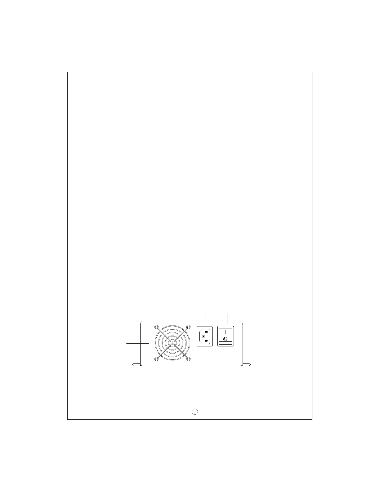
AC IN LET
F an
Venti lation
H ole
Figu re 2.1 Front Panel
ON/ OFF SWITCH
ON
AC INPUT
OFF
2
Assembly guidelines:
1.The charger should be turned OFF prior to battery connection. Suitable wire gauge
2. After plugging i n the AC power c ab le, flick t he ON/OFF (0/-) switch to the ON(- )
position. T he LED indicator on the switch will light up.
should be chosen based on rated charging current of the charger unit. Double-check
battery polarity before making the battery connection. Positive terminal of the charger
must be connected to + of the b attery and ne gative terminal to of the battery. Also,
make sure the positive and neg at ive terminals of the charger are not accidentall y
shorted together.
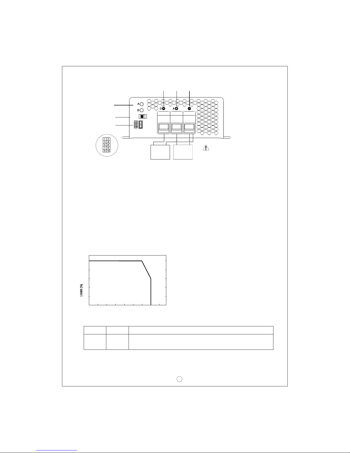
3.Derating c urve
3.1 Cha rging curren t VS temperature
AMBIENT TEMPERATURE ( )℃
20
40
60
80
100
-20 0 10 20 30 40 50 60 70 (HOR I ZONT AL)
Figu re 2.2 Ba ck P anel
LED
Indicator
Func tion
Connec t or
2/3/8 stage
select io n s witc h
{
+
+
Battery ABattery B
-
-
Stage 8/3/2
Please che ck batter y
polarity before
connection
WARNING :
Battery B
Positive
Battery A
Positive
Common
Negative
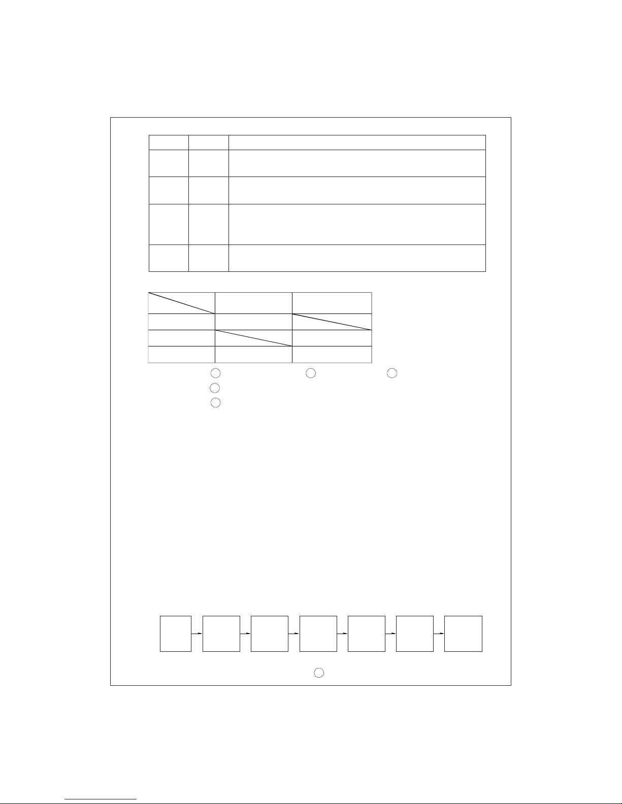
Pin No. Function Description
1,2 RY13 Relay contact rating (max.): 30V/1A. "Short" when bank A is fu ll.
"Open" when bank A is still charging .
4.Function description for CN100
3
Pin No. Function Description
3,4
5,6
9,10
7,8
RY14
RY15
RC-/RC+
GND/RTH
Rela y contact rating (max.): 30V/1A. "Short" when bank B is full.
Re lay contact rating (max.): 30V/1A. "Short" w hen the unit is working
Turn the output ON and OFF by electrical or dr y c ontact be tween
Temperature sensor which comes with the char ger can be conne cted
"Open" when bank B is still charging.
prope rly. "Open" w hen th e u nit has f ai le d or prot ect io n has a cti vated.
pin10 (RC+) and pin9 (RC-). Open: start charging. Short: s top charging.
to the unit to allow temperature compensation of the charging v oltage.
If the temperature sensor is not used , the charger ca n still w ork
norma lly.
5.LED In dication
6.Explanati on of operation logi c (charging stages):
PB - 1000 has a total of 3 charging m ode s to cho ose fr om, 2 stag es, 3 sta ges , and
8 stages. 8 stages charging differ from 2 stages with the addition of pulse, soft start,
analysis, recondition, float, and maintain stages. 2 stages provide simple and quick
charging. 3 stages is sim ilar to 2 stages with the exception of not shutting OFF after
the battery is fully charged. Lastly, 8 stages will allow charging to maximum capacity.
User can select bet ween 2,3 or 8 stages depending on their requirement.
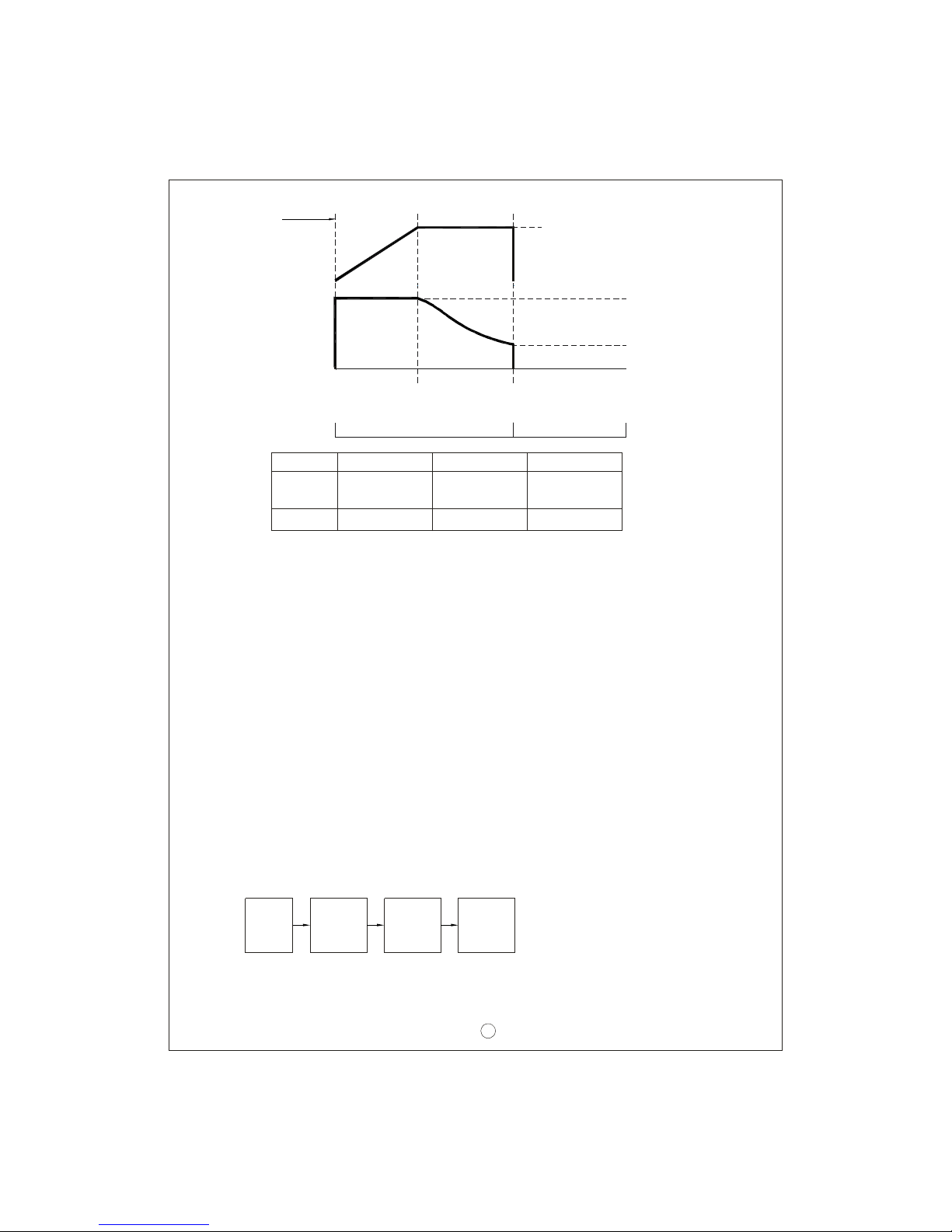
6.1 2 s tage charging (flick switch to "2" stage)
PB-1000 ha s channels A & B which can perform 2 stages charging individually.
Channel A will be the first to commence charging. During initial charge (stage 1),
charger will provide maximum current to the battery. The built-in fan will also turn
ON . As t he b att e ry s t ar t s t o g et f ul l, c ha r gin g cu rren t wi ll gradua l ly d ecre ase
(stage 2). When charging current decrease to less than 10% of max. LED indicator
wil l tur n Gr e en to s how a fu ll c harg e. Ch ann el A wil l tur n OF F w hile c ha r gi n g
commence at Channel B. After the battery at channel B is fully charged, PB-1000
will turn OFF its outputs.
Start
B ank A
C onstant
C urrent
Bank B
Cons tant
Curre nt
Bank A
Constant
Voltage
Bank B
Con stant
Volt age
Bank A
Charging
Ends
Bank B
Charging
Ends
Types of failure: 1
5
2 3
4
Battery disconnected
Activation of protection function (e.g. OTP, OVP, and Short)
Damaged battery Rever se polari ty
Incorrect battery voltage (e.g. PB-1000-12 connected to 24V battery)
Status
Color
Red
Orange
Green
Steady
Fail
Full Charging
Charging
Flashing
4
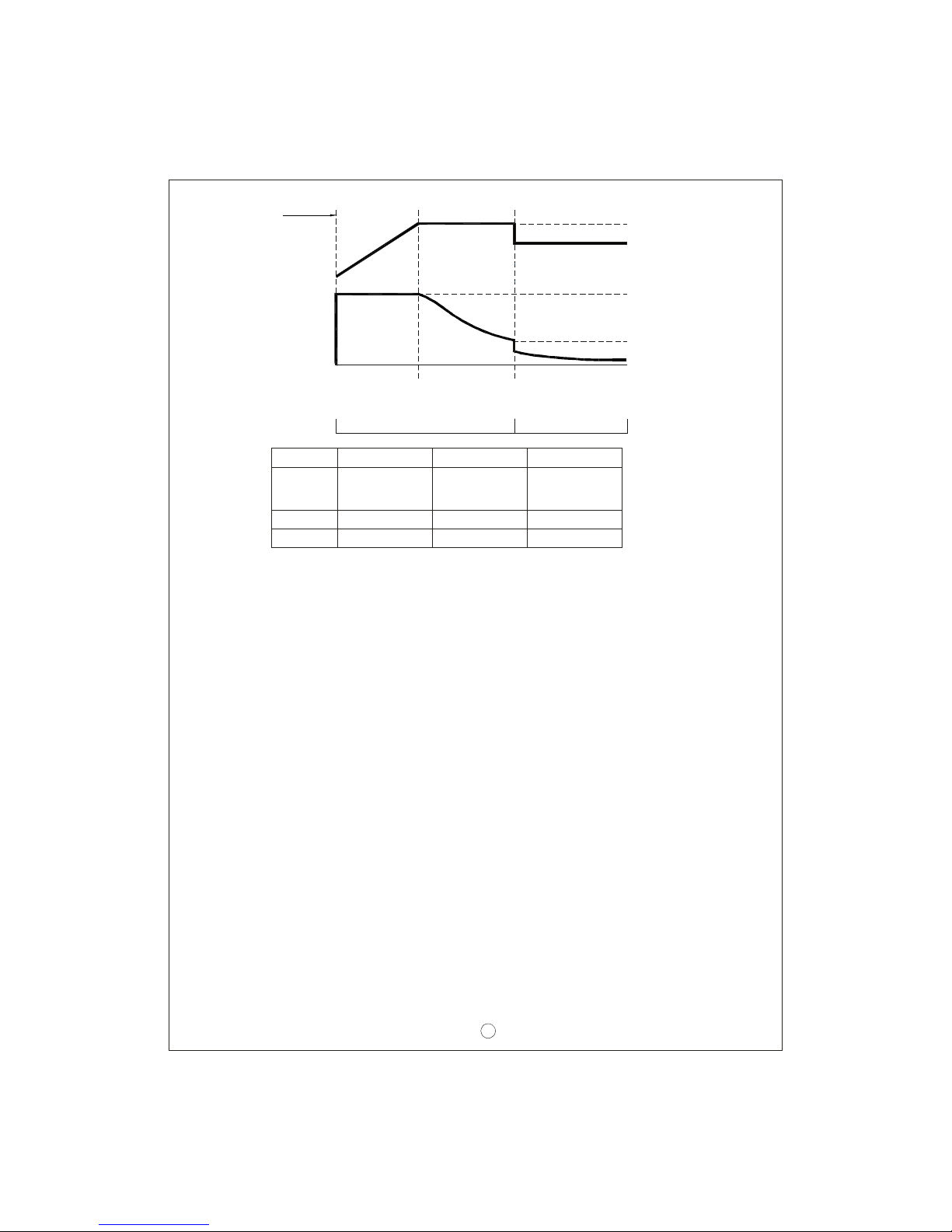
6.2 3 s tage charging (flick switch to "3" stage)
PB-1000 can only perform 3 stag es charging to Channel A. During initi al charge
(stage 1), charg er w ill provi de maximum cur rent to the ba ttery. The built-in fan
will also turn ON. As the battery starts to get full, charging current will gradually
dec rea se (s tage 2: prog rammed to l ast n o longe r tha n 24hrs). W hen cha rgin g
current decrease to less than 10% of max. LED indicator w ill turn Green to show
a full charge. The charge r will now mainta in a float charge voltage (stage 3).
State
Constant
Current
14.4V
PB-1000-12
28.8V 57.6V
PB-1000-24 PB-1000-48
Charge Current
Constant Current
stage 1 stage 2
Constant Voltage
Battery Full
Start
Charge Voltage
100%
10%
Orange Green
Color of LED
Fig ure 6.1 2 stage charging curve
Explanation for 2 stages charging curve
(0)Initial stage (battery analysis):
(1)Stage 1 (constant current):
(2)Stage 2 (constant voltag e):
Check batte ry voltage level to see if it is within the normal range, w hether or not
a ba ttery is connected, o r if the battery is already full and further charging is not
required.
A constant current is provided so the battery can be quickly charged to 2.4V per cell.
A constant voltage of 2.4V per cell is provided until the charging current naturally
tapers down to 10% then stop chargin g.
boost
V
Vboost
60A 34.7A 17.4A
Start
B ank A
C onstant
C urrent
Bank A
Constant
Voltage
Bank A
Floa t
Cha rge
5
State
Vboost
Vfloat
14.4V
13.8V
PB-1000-12
28.8V
27.6V
57.6V
55.2V
PB-1000-24 PB-1000-48
Figure 6.2 3 stage ch arging cur ve
Constant
Current 60A 34.7A 17.4A
100%
10%
Explanation for 3 stages charging curve
(0)Initial stage (battery analysis):
(1)Stage 1 (constant current):
(2)Stage 2 (constant voltag e):
(3)Stage 3 (Float voltage):
Check batte ry voltage level to see if it is within the normal range, w hether or not
a ba ttery is conn ecte d, o r if th e battery is alre ady full and further charging is not
required.
A constant current is provided so the battery can be quickly charged to 2.4V per cell.
A constant voltage of 2.4V per cell is provided until the charging current naturally
A float voltage of 2.3V per cell is provided so that the battery can maintain full charge.
tapers down to 10% then move on to stage 3.
Charge Current
Start
Charge Voltage
boost
float
V
V
Constant Current
stage 1 stage 2 stage 3
Constant Voltage
Battery Full
Orange Green
Color of LED
6.3 8 s tage charging (flick switch to "8" stage)
8 stage charging provides optimized charge to lead acid battery. It also prolongs
battery life and increase storage capacit y. Some of the main advantages are as
below:
Advantage of pulse stage: Use pulse current to revive aged battery.
Advantage of recondition stage: Al low full charge of bat tery.
◎
◎
*For applications that u tilize the charger (PB-1000) to charge batteries and supply.
System po wer simultaneously(e.g. UPS system), please select "3 sta ge" chargin g
for the best use of the charger.

6
Figure 6 .3 8 stage charg ing curve
Charge
Current
stage 1 stage 2 stage 3 stage 4 stage 5 stage 6 stage 7 stage 8
Charge
Voltage
Pulse Soft
Start
Constant
Current
C ons ta nt
Volt age
Ana lysis Float Ma intai n
Orange Green
Color of
LED
Explanation for 8 stages charging curve
(0)Initial stage (battery analysis):
(1)Stage 1 (pulse charging):
(2)Stage 2 (soft sta rt):
(3)Stage 3 (constant current):
(4)Stage 4 (constant voltage):
Check batte ry voltage level to see if it is within the normal range, w hether or not
a ba ttery is connected, o r if the battery is already full and further charging is not
required.
Pulse charging is used to revive tired lead acid battery which is either improperly
charged/discharged or allowed to self-discharge as occurs during non-use. Basically,
help to restore its norma l chemical properties.
Use low charge volt age and curr ent to prepare th e ba ttery to accept u pco min g
A high constant curre nt is provided so the battery can be qu ickly charged to 2.4V
per cell.
A constant voltage of 2.4V per cell is provided until the charging current naturally
tapers down to a low level.
bulk charging, so a better charge can be a pplied.
St ar t
Bank A
Pulse
Charge
Bank B
Pulse
Charge
Bank A
Sof t
St art
Bank B
Sof t
St art
Bank A
Bank B
Bank A
Bank B
Constant
Constant
Constant
Constant
Curre nt
Curre nt
Voltage
Voltage
Bank A
Float
Charge
Bank B
Float
Charge
A/ B maintai n charge cycl e
Bank A
Bank B
Analysis
Analysis
Bank A
Bank B
Mainta in
Mainta in
B ank A
B ank B
R econ -
dition
R econ -
dition
Re cond
A dva n tag e o f f loa t an d ma int ai n s tage : Aft er L ED t urns gre en, m ain ten a nce◎
charge is provided so the battery is always in a full state. User will have access
to a full battery whenever it is disconnected from the charger.
7.Function description
7 Input v oltage.1
PFC7.2
7.3 Remote control
unit may be non-functional also the active PFC circuit may fail or get damaged.
with full lo ad at the ou tput. On the other hand, if the inp ut vo ltage is >230V o r
outpu t is not a t full load, th e PF will drop below 0.95.
◎Input voltage range is 90~264Vac or 12 7~370Vdc.
◎T he provided inpu t vo ltag e must fall w ithin the spe cifie d range otherwis e th e
◎Built-in active PFC circuit: PF>0.95 when input voltage is between 90~230Vac
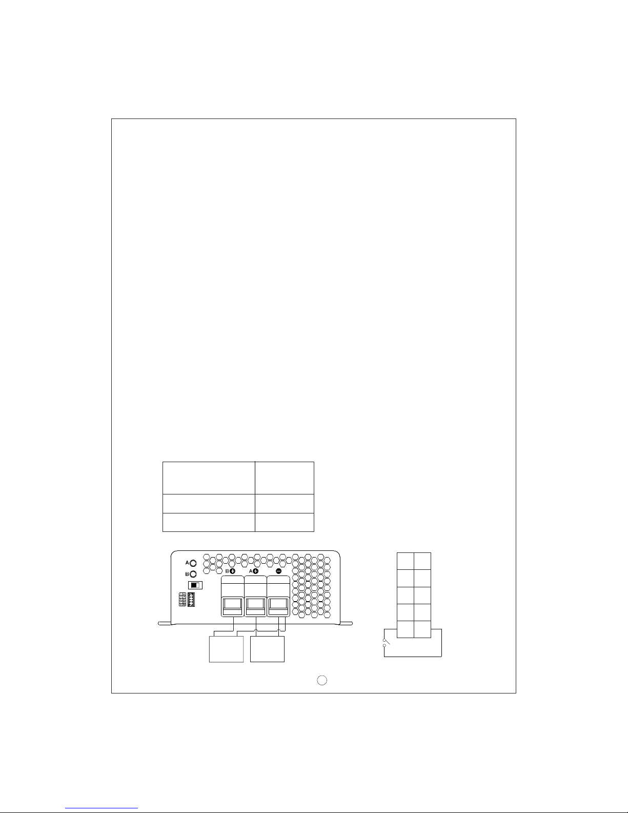
The charger can be turned ON/O FF by using the "remote control" function.
SW
91 0
CN100
RY13
RY14
RY15
GND
RC-
RY13
RY14
RY15
RTH
RC+
12
Between RC+ (pin10)
an d RC- (pin 9)
SW open
SW closed
Ch arge r
ON
OFF
(5)Stage 5 (analysis):
Stage 6 (rec ondition boost charge):(6)
Stage 7 (float ch arge):(7)
Stage 8 (maintain):(8)
The charger will stop ch argi ng fo r 2 m inutes to de term ine battery status. If the
Boost voltage is provided to recondition the battery storage capacity to its original
state.
A float voltag e o f 2.3V per ce ll is provided for extended period of tim e so that the
Mai ntenance ch arge is prov ided to c omp ensate for b atte ry self-d isch arge an d
extend battery life.
battery c an m aintain full charge.
battery voltage is higher than 2.1 V per cell, the battery is determined as OK and
will move on to stage 6. If the battery voltage is lower than 2.1V per cell, the battery
fail indication wi ll co me O N and the charger will stop charg ing.
+
+
Batte ry A
Battery B
-
-
St age 8/3/2
7

7.4 Tw o battery banks
The charge r can be hoo ked up t o tw o ba t tery ba nks (A and/o r B) . Connect the
battery bank(s) as below. If you are connecting 2 battery banks at the same time,
kee p in mind that it m ust sha re a common ground .
+
+
+
+
Battery A
Battery A
Battery B
Battery B
-
-
-
-
Stage 8/ 3/2
Stage 8/ 3/2
Stage 8/ 3/2
7.5 2, 3, or 8 stage charging mode selection
Th e ch arge r fea tur es u ser s el ec tab le 2 , 3, o r 8 s tag e ch argi ng. The c har gi ng
profile is selected by moving the slide sw itch on the back panel.
8

Swi tch
Slide right
Mid dle
Slide left
C hargin g mod e
2 sta ge charging
3 sta ge charging
8 sta ge charging
Stage 8/3/2 +
+
Ba tte ry A
Ba ttery B
-
-
Stage 8/3/2
7.6 Reverse polarity protection
7.7 Fan sp eed con trol
7.8 Charger OK re lay (RY15)
7.9 Ou tput OK relay (RY13 & RY14)
With built-in battery reverse polarity detection circuit. When the battery is connected
in rever se at the output terminal of the charger, the output relay circuit will remain
ope n.
With bu ilt-in fan speed control circu it, th e fa n wil l aut omatically chan ge speed
dep ending on load condition.
9
1
Wor king n ormal ly
Charger
Failure or pro tection
func tion ha s activ ated
ON (s ho r t)
Be tween pi n5 and pin 6
OFF ( ope n)
10
CN100
RY13
RY14
RY15
GND
RC-
RY13
RY14
RY15
RTH
RC+
2
RY15
Bank A
Bank B
Bank A full
Bank B full
Color of LED A
Col or of LED B
Cha rgin g
Cha rgin g
Between pin1 and pin2
Between pin3 and pin4
O N (s hort)
O N (s hort)
Green
Green
OF F (o pen)
OF F (o pen)
Orange
Orange
1.Ban k A OK ( RY1 3)
2.Ban k B OK (RY1 4) 9
1
10
CN100
RY13
RY14
RY15
GND
RC-
RY13
RY14
RY15
RTH
RC+
2
RY14
RY13
9
8.Wiring for battery
9.Sugge sted battery capacity
Note: 1.Using battery capacity larger than the suggested value will not lead to damage
of the batte ry. The main drawba ck is it may take longer t o fu lly charg e th e
battery.
2.If you're unsure about max allowable charging current of your battery, please
refer to the battery's technical s peci fication or consult its man ufa cturer.
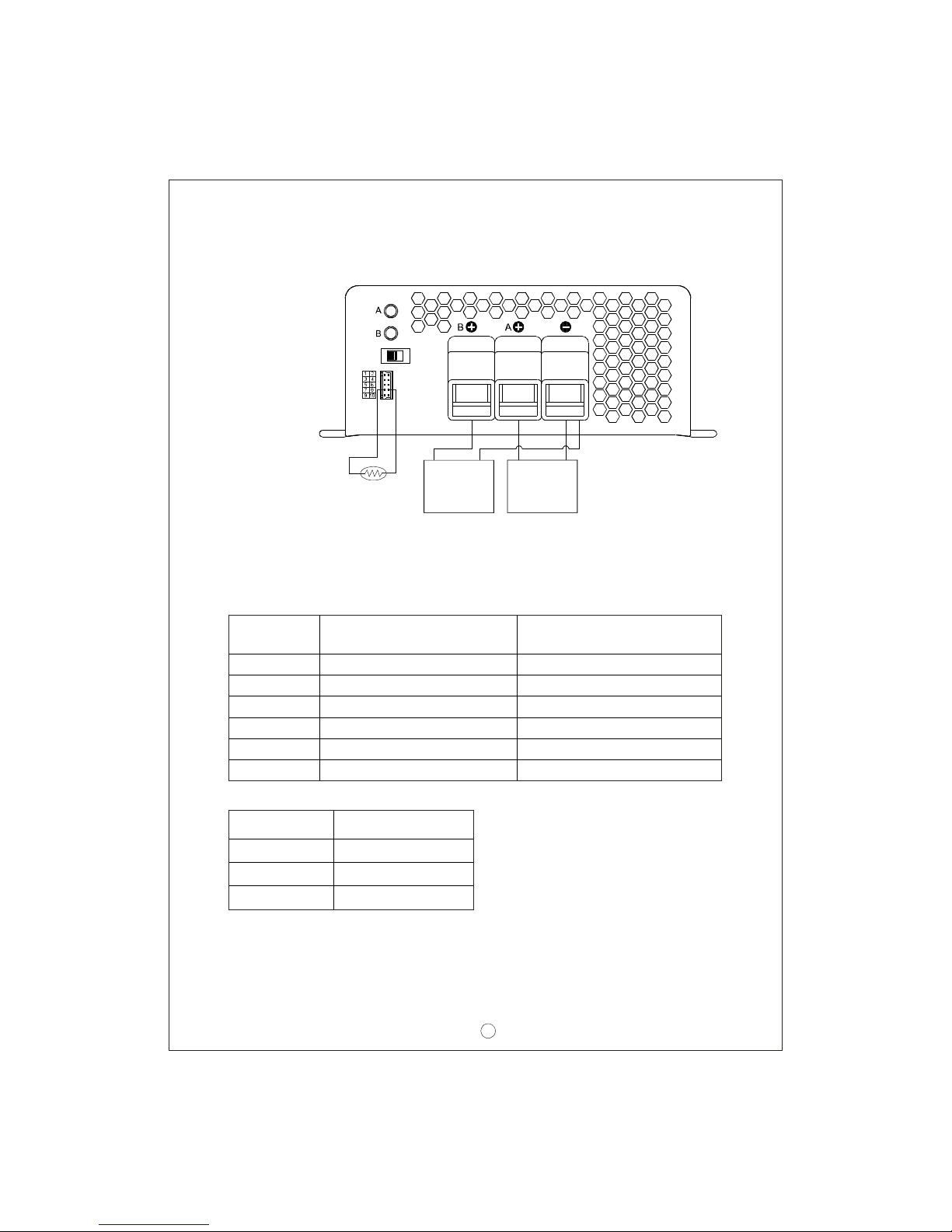
Select suit able wire gu age based on rated charg ing current. Ref er to the following
table for minimum wire gauge. We highly recommend using RED wire for + connection
and BLACK wire for-connection :
AWG
14 2.1 12
12 3.3 22
10 5.3 35
7 10 46
6 16 60
4 25 80
CROSS SECTION(mm )
2Max. Cu rrent( A)
UL1015(600V 105 )℃
Model
P B-10 00- 12 200-600AH
P B-10 00- 24
P B-10 00- 48
120-350AH
60-175AH
Battery capacity
10 Temp erature compensation7.
Temperature sensor which comes with the charger can be connected t o the unit
to allow temperature compensation of the charging voltage. If the tem perature
sensor is not used, the ch arger can still w ork normally.
++
Battery ABattery B
--
NTC
Stage 8/3/2
10
The t emperature
sensor can either
be attached to the
batte ry or p laced
in its surrounding
envir onmen t.
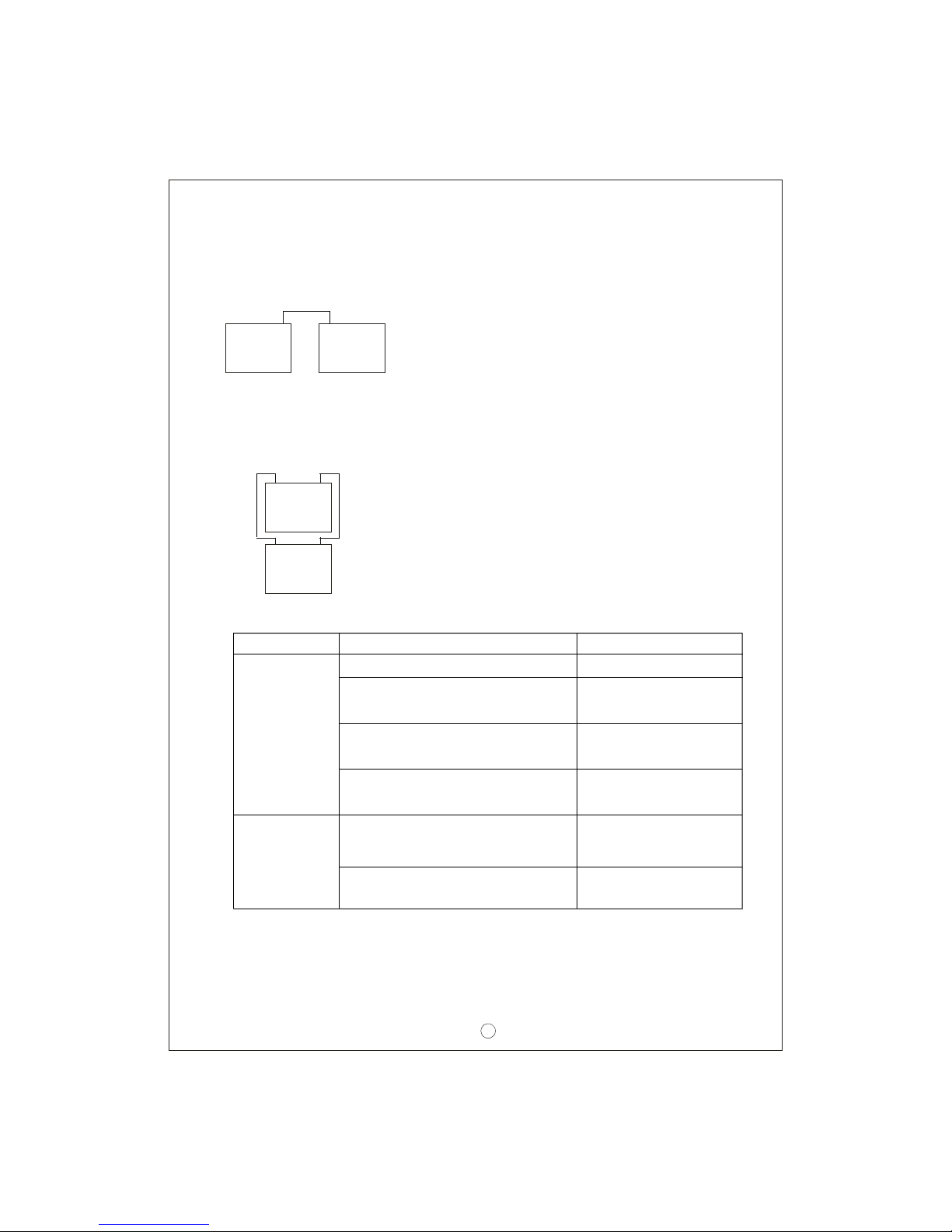
11.Failure correction notes
If you are not abl e to clear the failure condition, plea se contact Mean Well or
any o f our di strib utors for repair ser vice.
WARNING : This is a class A product. In a domestic environment this product
ma y ca use r adi o i nt erfe r en ce i n wh ic h c ase t he u se r ma y be
required to take ade quate measures.
Status
Unable to
cha rge
the battery
LED indicator
doe s not turn
Gre en after a
long charging
period
Possible reasons
ON/OFF switch in th e OFF position Switch to the ON position
Reconnect using the
right polarity
Use battery with the
cor rect voltage
Make sure input sou rce
is between 90~264VAC
Replace with a new
battery
Replace with suitable
wire gauge
Battery reverse polarity
Battery with higher voltage is
con nected
Input AC vol tage is too low
Battery exceeded lifespan or
damaged
Output cables are too thin
Solutions
10.Serie s and paral lel connection o f batteries
1.Batter ies i n series
2.Batter ies i n parallel
Vo ltag e ca n be do uble d wh en 2 bat teri es a re c onn ecte d in s eri es. H ow eve r, th e
Wh en 2 ba t ter ies a re c onn e ct ed i n pa r all e l, v o lta g e r ema i ns t he s a me an d th e
capacity (Ah) d oubles. For example , 2 x 12V 100Ah batteries connected in parallel
= 12V 200Ah.
capacity (Ah) will remain the same. For example, 2 x 12V 100Ah batteries connected
in series = 24V 100 Ah.
+
+
+
+
Battery
Battery
Battery
Battery
-
-
-
-
11

Table of contents
Other Meanwell Batteries Charger manuals

Meanwell
Meanwell NPB-450 NFC Series User manual

Meanwell
Meanwell ENC Series User manual

Meanwell
Meanwell PB-230-48 User manual

Meanwell
Meanwell PA-120 User manual

Meanwell
Meanwell DBU-3200 Series User manual

Meanwell
Meanwell PB-600 User manual

Meanwell
Meanwell GC160 User manual

Meanwell
Meanwell RPB-1600 Series User manual

Meanwell
Meanwell PB-230 User manual

Meanwell
Meanwell GC120 User manual


 technical information")


