15
16
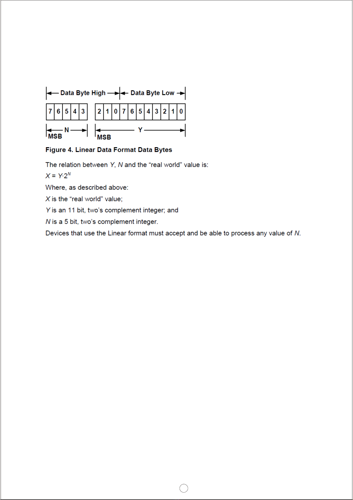
RTH+
RTH-
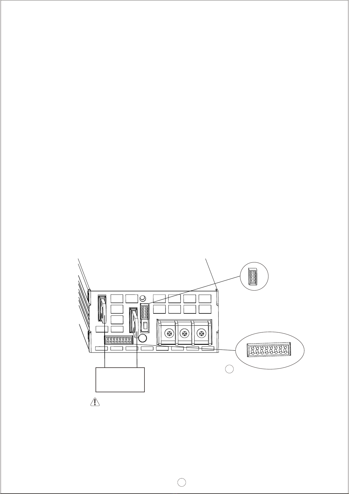
Temperature sensor(NTC, 5KOhm) comes along with the charger can be connected to the unit to allow temperature
compensation of the charging voltage.
Installation Procedure:
Please make sure the charger is OFF before connecting the battery to the output terminal. Choose a
cable with suitable wire gauge according to the charging current to connect between the charger and
the battery. Battery polarity must be connected correctly:Terminal(+) to Battery(+); Terminal(-) to
Battery(-), and take notice that the positive and negative ends are not shorted.
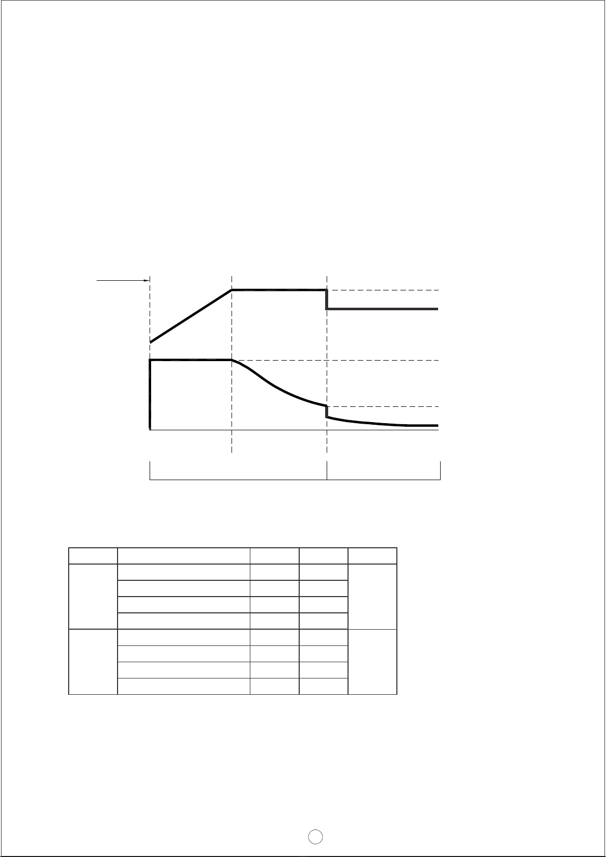
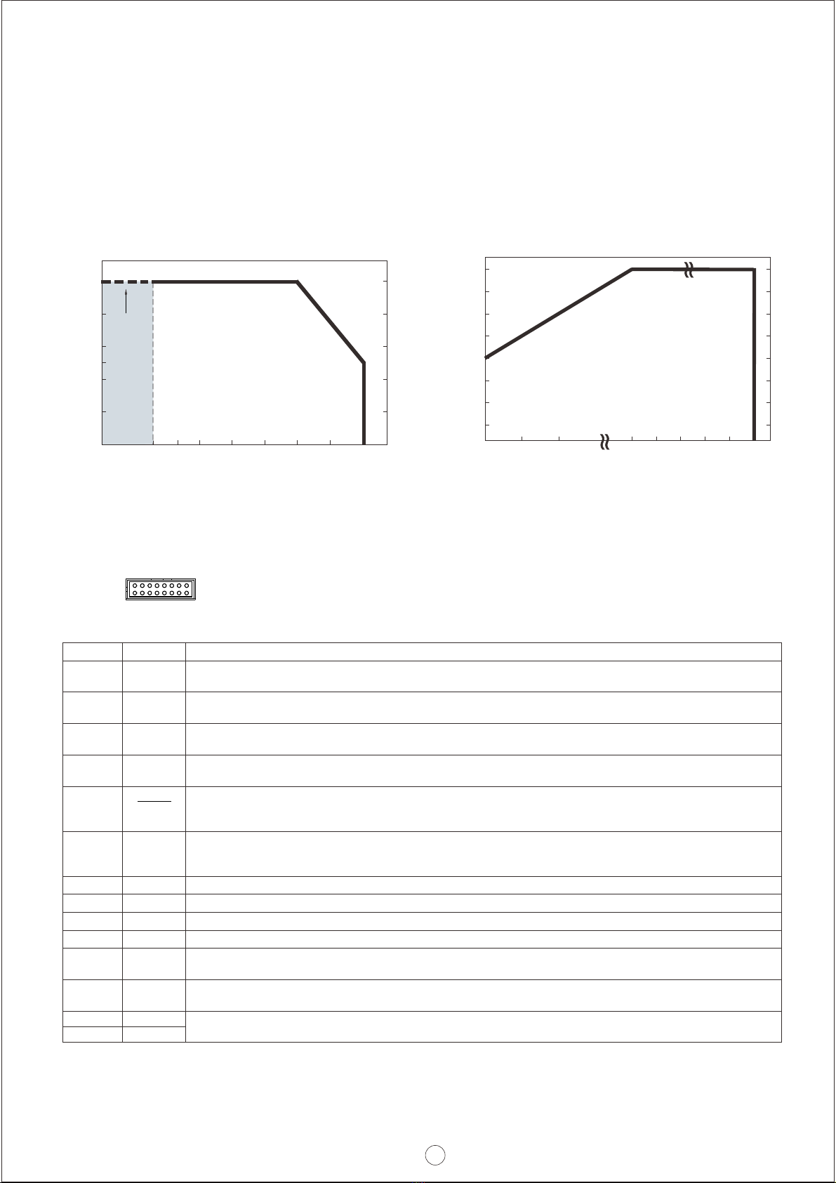
3.Derating Curve
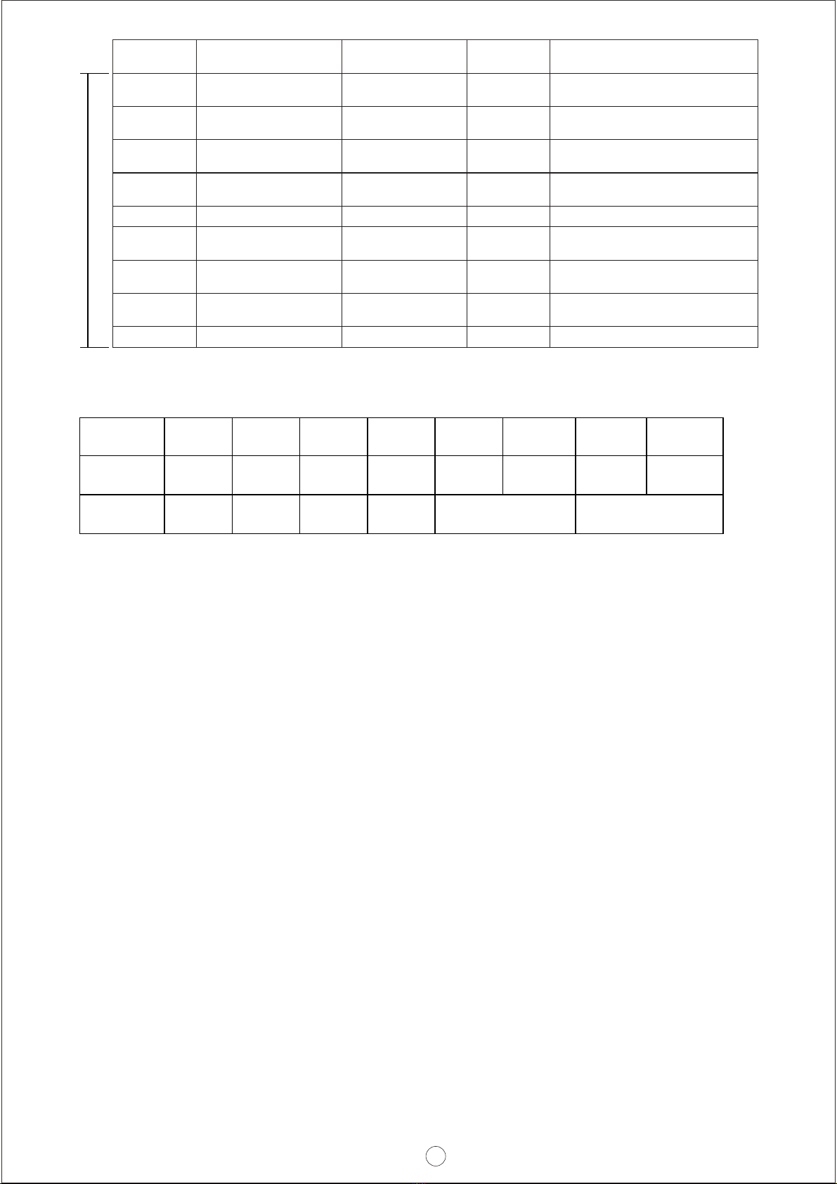
4.Pin Assignment
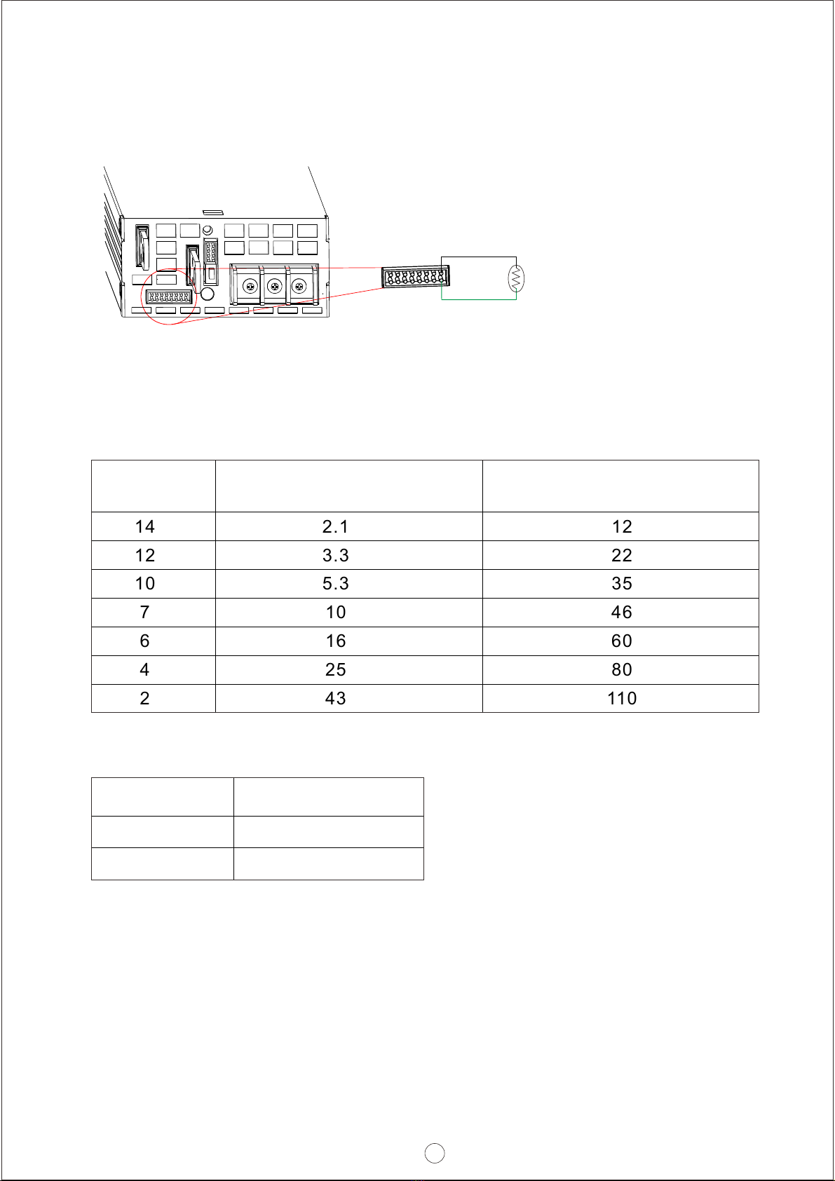
3.1 Charging current vs Temperature
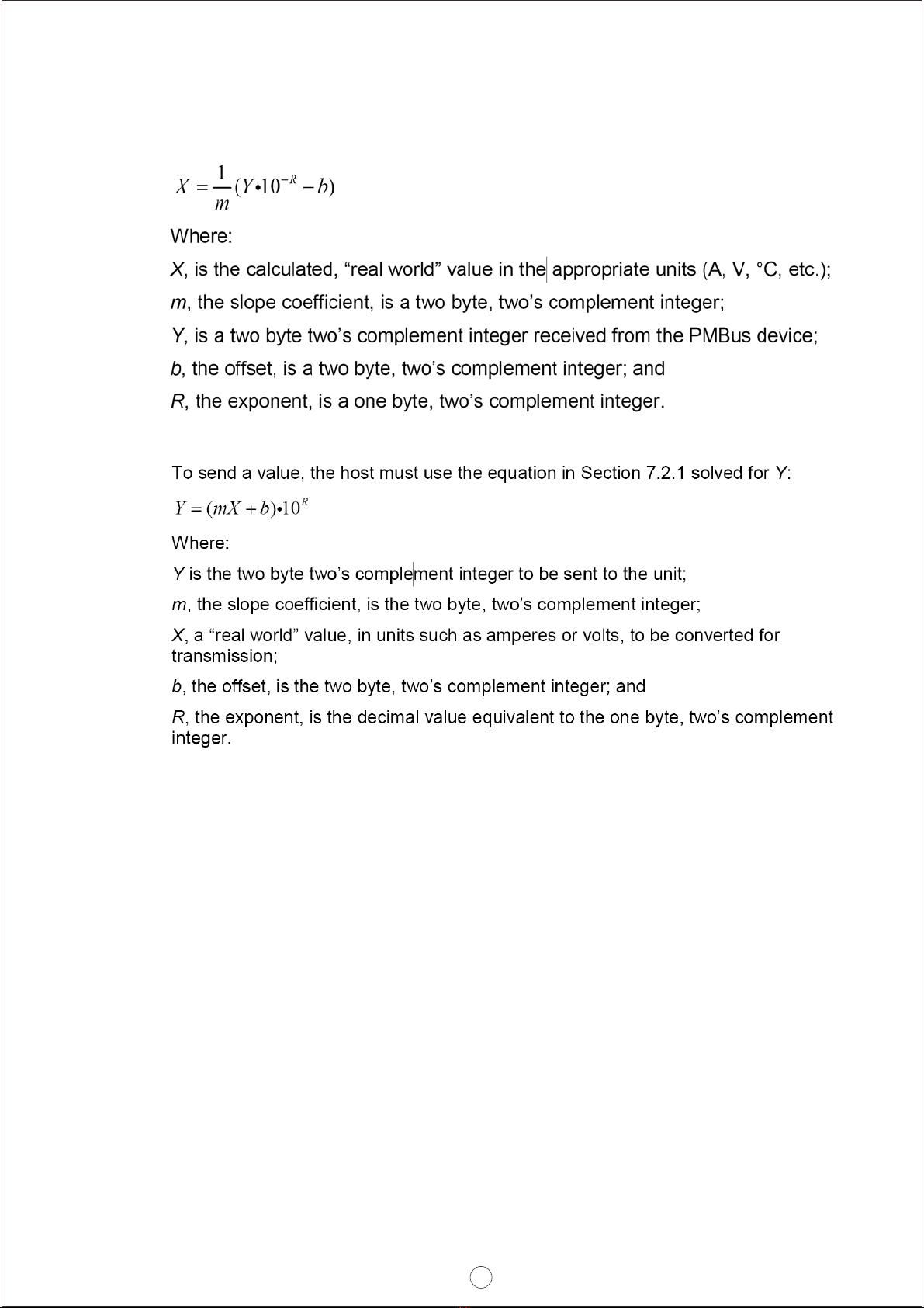
3.2 Charging current vs Input Voltage
AMBIENT TEMPERATURE ( )℃
LOAD (%)
LOAD (%)
INPUT VOLTAGE (VAC) 60Hz
CN1
230VAC
Input only
-30 -25 0-10 15 30 50 60 70
20
40
60
50
80
100
(HORIZONTAL) 90 100 115 180 264
80
90
100
70
60
50
40
30
1
2
15
16
2
Pin No. Function Description
4
2
7,8,9
10
5
6
3
1
12
11
Remote
ON-OFF
GND-AUX
DC-OK
T-ALARM
+5V-AUX
+12V-AUX
PV
PC
A0,A1,A2
D0
Auxiliary voltage output GND.
The signal return is isolated from the output terminals (+V & -V).
Auxiliary voltage output, 4.5~5.5V, referenced to GND-AUX (pin2).
Auxiliary voltage output, 10.6~13.2V, referenced to GND-AUX (pin2).
The maximum load current is 0.3A. This output has the built-in "Oring diodes" and is not controlled by “Remote ON-OFF
The maximum load current is 0.8A. This output has the built-in "Oring diodes" and is not controlled by “Remote ON-OFF”.
Connection for output voltage programming. (Note.1)
High (4.5 ~ 5.5V) : When the internal temperature exceeds the limit of temperature alarm, or when Fan fails.
Low (-0.1 ~ 0.5V) : When the internal temperature is normal, and when Fan works normally.
The maximum sourcing current is 10mA and only for output(Note.2)
Connection for output current programming. (Note.1)
Low (-0.1 ~ 0.5V) : When Vout 16V/32V . The maximum sourcing current is 10mA and only for output. (Note.2)≧±1V
DC OK is associated with battery low protection.
High (4.5 ~ 5.5V) : When the Vout 16V/32V .≦±1V
PMBus interface address lines. (Note.1)
DIP-switch interface lines for charging curve selection. (Note.1)
The unit can turn the output ON/OFF by electrical signal or dry contact between and . (Note.2)Remote ON/OFF +5V-AUX
Short (4.5 ~ 5.5V) : Power ON ; Open (-0.1 ~ 0.5V) : Power OFF ; The maximum input voltage is 5.5V.
Note1: Non-isolated signal, referenced to the [-V(signal)].
Note2: Isolated signal, referenced to GND-AUX.
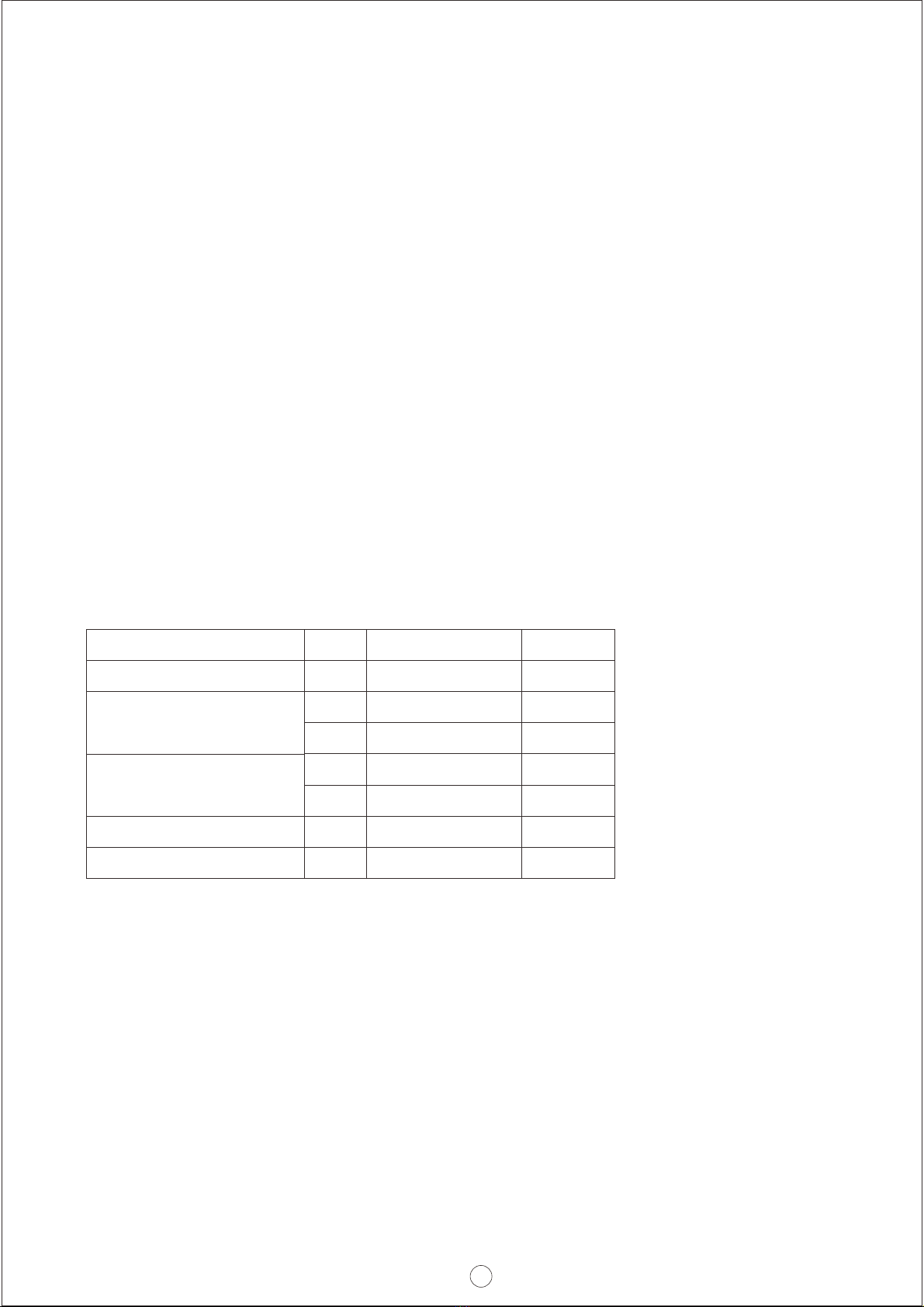
13
14
+V (Signal)
-V (Signal)
Positive output voltage signal.
Negative output voltage signal.
It cannot be connected directly to the load.
It is for certain function reference; it cannot be connected directly to the load.