MED Associates SHUTTLE BOX User manual

instrumentation and software for research
SHUTTLE BOX
FOR ACTIVE & PASSIVE AVOIDANCE
MED-APA
INSTALLATION GUIDE
DOC-015
Rev. 1.4
Copyright ©2013
All Rights Reserved
Med Associates Inc.
P.O. Box 319
St. Albans, Vermont 05478
Phone: 802.527.2343
Fax: 802.527.5095
www.med-associates.com


MED ASSOCIATES INC.
MED-APA SHUTTTLE BOX PACKAGE
- ii -
DOC-015 Rev 1.4 Copyright © 2013
Med Associates, Inc.
Table of Contents
Chapter 1 | Introduction................................................................................................1
Chapter 2 | Installing Interface Cards........................................................................2
Drivers and Software.................................................................................................................... 2
PCI Computer Interface Card...................................................................................................... 2
Decoder Card................................................................................................................................. 2
SmartCTRL Interface and Power Supply................................................................................... 3
Chapter 3 | Wiring Instructions...................................................................................5
IR Controller................................................................................................................................... 5
Grid Scramblers............................................................................................................................. 6
Shock and A/B Switch Cable........................................................................................................ 7
Chapter 4 | Optional Guillotine Door ..........................................................................8
Appendix A | Contact Information...............................................................................8
MED ASSOCIATES INC. MED-APA SHUTTLE BOX PACKAGE
- 1 -
DOC-015 Rev 1.4 Copyright © 2013
Med Associates, Inc.
CHAPTER 1 | INTRODUCTION
The Med Associates, Inc. Shuttle Box System will arrive with most if the components wired
correctly, therefore the system requires minimal assembly. This manual serves as a guide to
complete the wiring of the system. Should further assistance be required, please visit
www.med-associates.com.
For software information, refer to the documentation that was delivered with the Shuttle Box
software application.
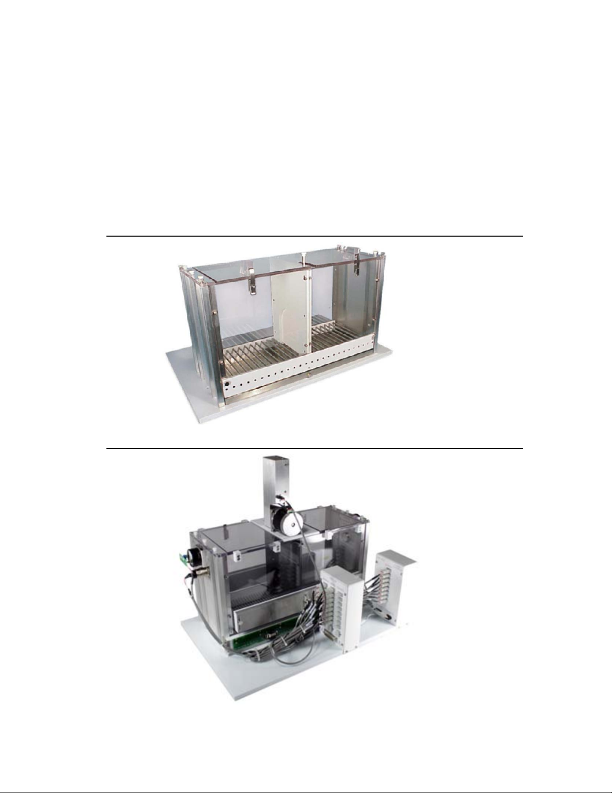
Figure 1-1 – Shuttle Box Chamber
Figure 2.1 - Shuttle Box Chamber with IR Strips and Optional Automatic Guillotine Door
MED ASSOCIATES INC. MED-APA SHUTTLE BOX PACKAGE
- 2 -
DOC-015 Rev 1.4 Copyright © 2013
Med Associates, Inc.
CHAPTER 2 | INSTALLING INTERFACE CARDS
Drivers and Software
Refer to the Instructions for installing MED-PC, Delphi, and the hardware drivers, as well as
running the hardware configuration utility in DOC-010, MED-PC IV User’s Manual. If a PC was
purchased from MED Associates Inc., the software and drivers will already be installed. If
necessary, use the Hardware Configuration Utility to set user-defined options for file format, file
naming, data path, and backup.
PCI Computer Interface Card
If the computer was purchased from MED Associates, the PCI card will be factory-installed.
Otherwise, install the PCI Computer Interface Card into an available full height PCI slot in the
computer following the manufacturer’s instructions provided with the computer. When
finished, turn the computer on. The Found New Hardware Wizard should begin automatically; if
it does not, select Start |My Computer | Control Panel | Add New Hardware. The drivers are
located on the MED-PC® installation CD and are automatically installed with MED-PC.
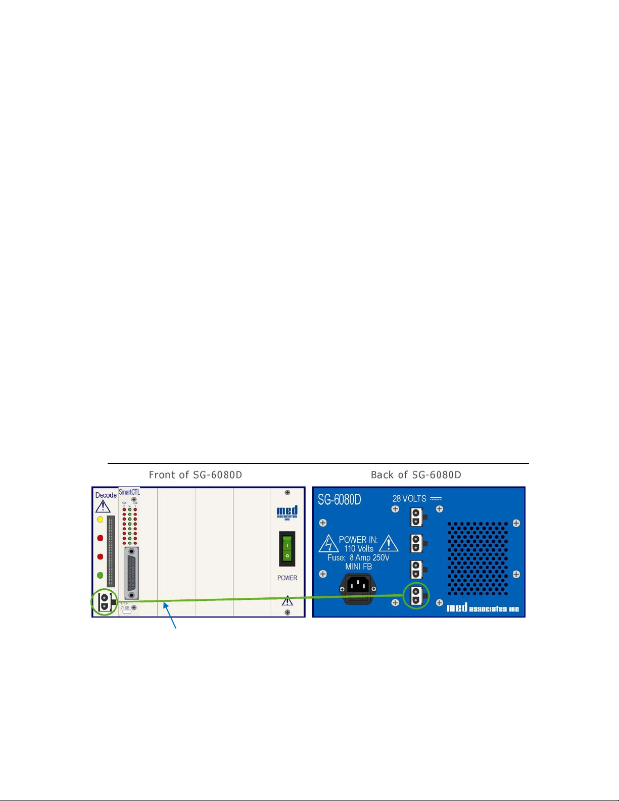
Decoder Card
To install the Decoder Card first turn off the power to the interface cabinet (SG-6080D or SG-
6510D). The decoder card (DIG-700G) should be installed in the leftmost slot of the interface
cabinet. Connect an SG-210CP two-pin Molex cable from the front of the decoder card to a 28
VDC power supply in the rear of the cabinet. (See Figure 2-1.)
Figure 2-1 – 28Volt Connection to Decoder Card
SG-210CP-25 2-Pin Molex Cable
MED ASSOCIATES INC. MED-APA SHUTTLE BOX PACKAGE
- 3 -
DOC-015 Rev 1.4 Copyright © 2013
Med Associates, Inc.
SmartCTRL Interface and Power Supply
Before connecting components, turn off the power on the computer and the interface cabinet.
Install the SmartCTRL Interface Card(s) in sequence, starting with Box 1 on the leftmost slot next
to the Decoder card. Make sure the ports and address offsets are set according to the
instructions in DOC-013 SmartCtrl Manual.
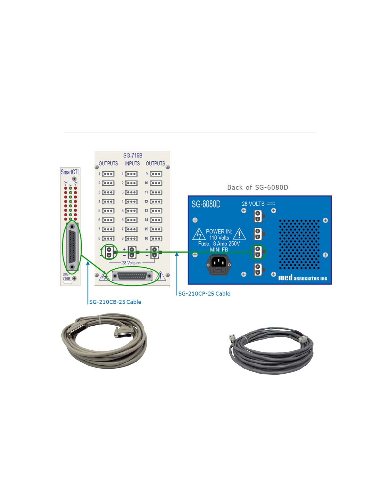
Connect the SmartCTRL card to the Control Panel using an SG-210CB Serial Port cable. Provide
28 Volts to the Control Panel from the SG-6080D using an SG-210CP-25 Cable. See Figure 2-2.
Figure 2-2 – Connect the DIG-704PCI-2 to the DIG-700G Decode Card.
SG-210CB Serial Port Cable SG-210CP-25 Cable
MED ASSOCIATES INC. MED-APA SHUTTLE BOX PACKAGE
- 4 -
DOC-015 Rev 1.4 Copyright © 2013
Med Associates, Inc.
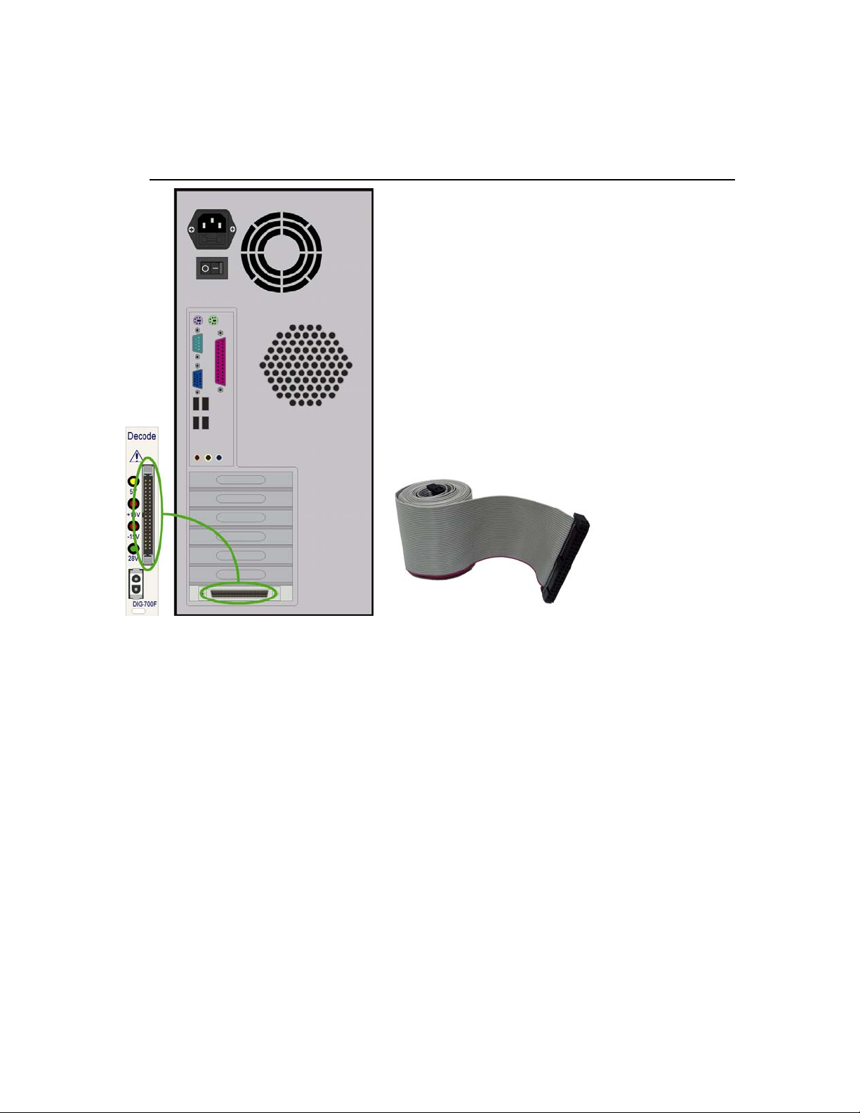
Connect the DIG-704PCI-2 card to the DIG-700G Decode Card using the DIG-700C Ribbon Cable.
Figure 2-3 – Connect Decoder Card to PCI Card in Computer using DIG-700C Ribbon Cable
DIG-700C Ribbon Cable
MED ASSOCIATES INC. MED-APA SHUTTLE BOX PACKAGE
- 5 -
DOC-015 Rev 1.4 Copyright © 2013
Med Associates, Inc.
CHAPTER 3 | WIRING INSTRUCTIONS
IR Controller
A pair of infrared (IR) strips containing transmitters and receivers attaches to the front and back
walls of the shuttle box chamber to detect the animals’ movement throughout the chamber.
These strips can be adjusted by setting the photo beam height to accommodate different sized
rats and mice. The IR strips connect to an eight-channel I/R control box (ENV-253C) to transmit
data to MED-PC software.
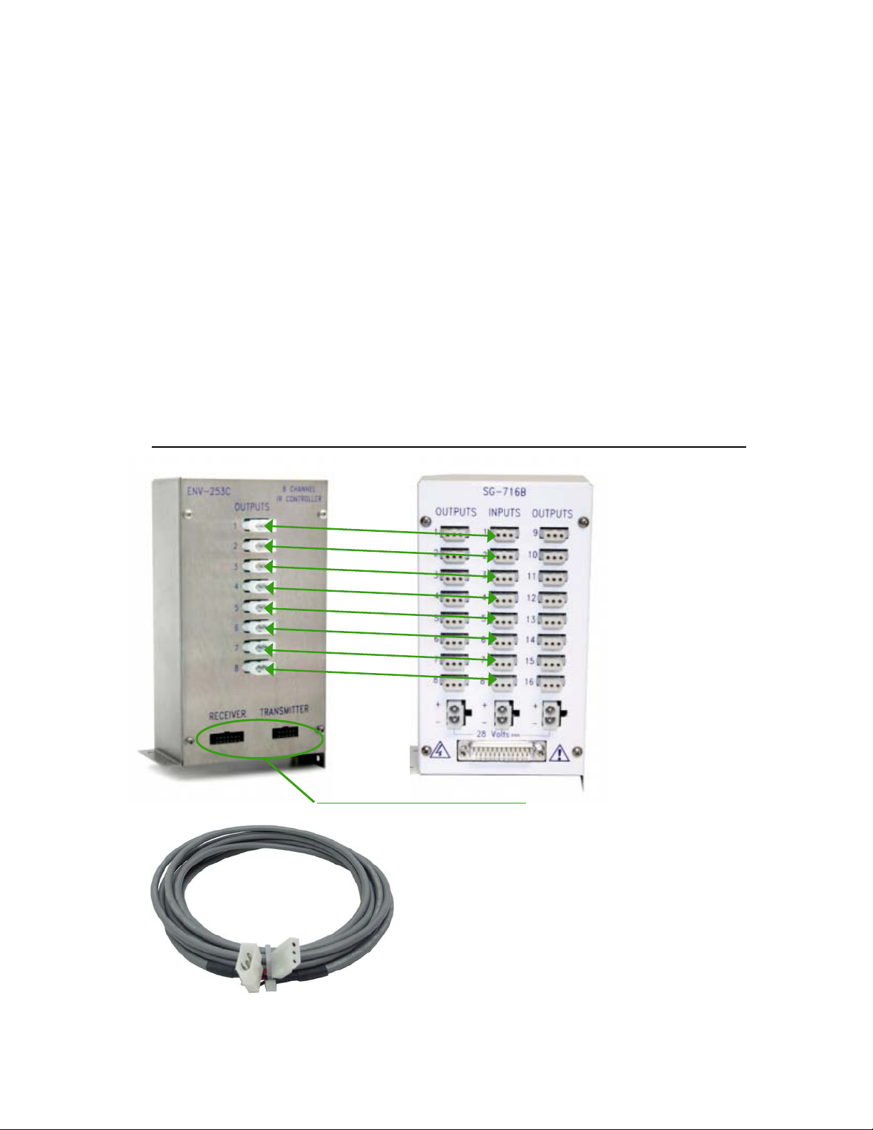
Connect the outputs from the ENV-253C eight-channel IR controller to the inputs on the SG-
716B control panel using the SG-216A 3-pin Molex cable.
See Figure 2-2 for connections from the SG-716B Control Panel to the DIG-716B SmartCtrl card
and the 28Volt connection from the power source to the SG-716B.
Figure 3-1 – ENV-253C 8 Channel IR Controller
Connect to IR pairs (ENV-256-8S)
SG-216A 3-Pin Molex Cable
MED ASSOCIATES INC. MED-APA SHUTTLE BOX PACKAGE
- 6 -
DOC-015 Rev 1.4 Copyright © 2013
Med Associates, Inc.
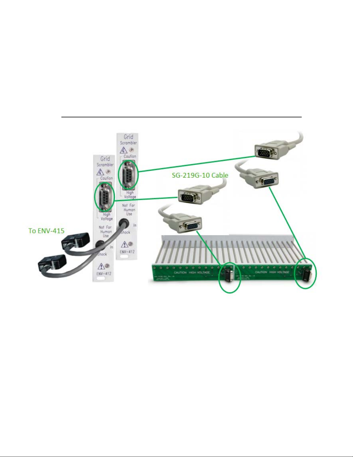
Grid Scramblers
Connect each ENV-412 Grid Floor Scrambler to the corresponding grid floor using SG-219G-10
cables. Please note that there are two ENV-412 Scramblers in the cabinet. The Scrambler on the
left must connect to the grid floor on the left side of the Shuttle Box, and the Scrambler on the
right must connect to the grid floor on the right side of the Shuttle Box.
Figure 3-2 – Grid Scrambler Connection to Quick Disconnect Shuttle Grid Floor Harness

MED ASSOCIATES INC. MED-APA SHUTTLE BOX PACKAGE
- 7 -
DOC-015 Rev 1.4 Copyright © 2013
Med Associates, Inc.
Shock and A/B Switch Cable
Using the SG-219SA cable, connect the MED Connection Panel Outputs to the ENV-410B and
ENV-415 Switch and Stimulator interface cards. Refer to Figure 3-3.
Figure 3-3 – SG-219SA Cable Connections
SG-219SA
Output 6
Output 7
Output 8
MED ASSOCIATES INC. MED-APA SHUTTLE BOX PACKAGE
- 8 -
DOC-015 Rev 1.4 Copyright © 2013
Med Associates, Inc.
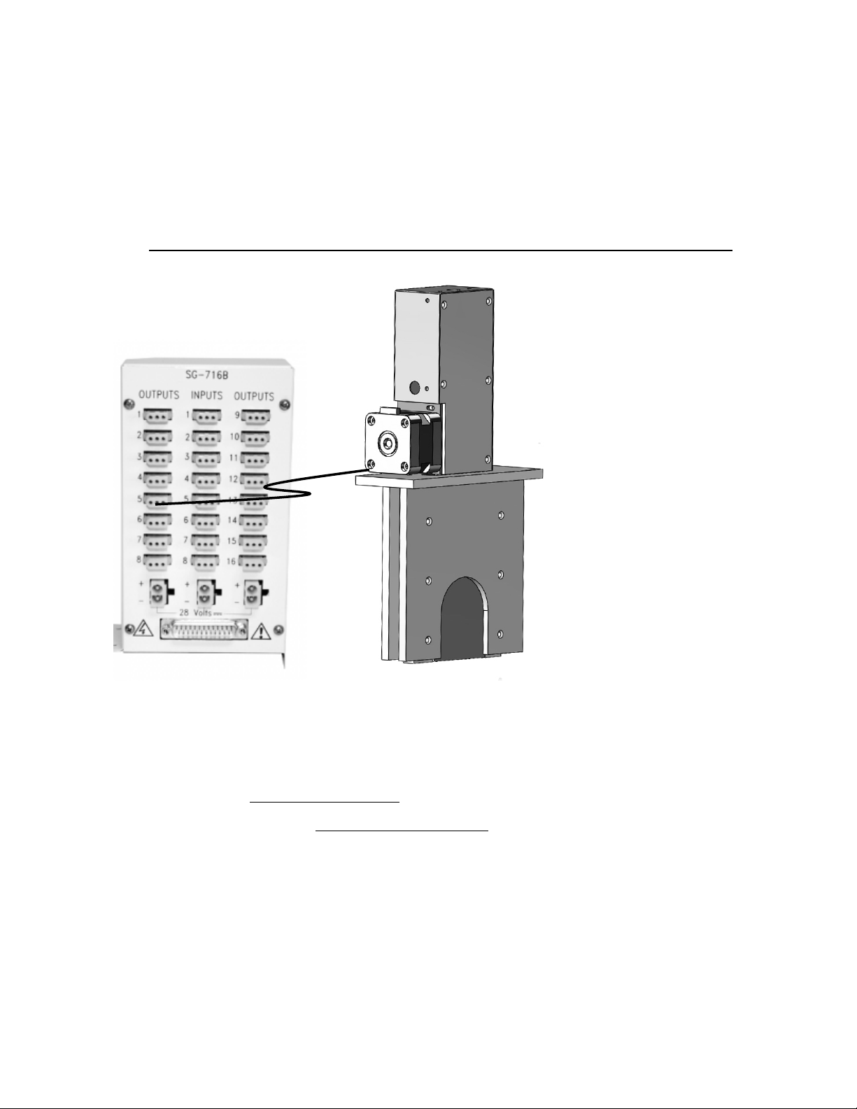
CHAPTER 4 | OPTIONAL GUILLOTINE DOOR
If the system requires the connection of an Automatic Guillotine Door, simply connect it to the
available output port (output 5 is used with standard MedState protocol) on the Connection
Panel as shown in Figure 4-1.
Figure 4-1 – Guillotine Door Connection
APPENDIX A | CONTACT INFORMATION
Please contact Med Associates, Inc. for information regarding any of our products.
Visit our website at www.med-associates.com for contact information.
For technical questions, email support@med-associates.com.
Table of contents
Other MED Associates Medical Equipment manuals


Popular Medical Equipment manuals by other brands


Getinge
Getinge Arjohuntleigh Nimbus 3 Professional Instructions for use

Mettler Electronics
Mettler Electronics Sonicator 730 Maintenance manual

Pressalit Care
Pressalit Care R1100 Mounting instruction

Denas MS
Denas MS DENAS-T operating manual

bort medical
bort medical ActiveColor quick guide

AccuVein
AccuVein AV400 user manual


