MED Associates PHM-15 Series User manual

instrumentation and software for research
PROGRAMMABLE INTRACRANIAL SELF-
STIMULATION (ICSS) CURRENT STIMULATOR
PHM-15X
USER’S MANUAL
DOC-012
Rev. 2.3
Copyright ©2019
All Rights Reserved
Med Associates, Inc.
P.O. Box 319
St. Albans, Vermont 05478
Phone: 802.527.2343
Fax: 802.527.5095
www.med-associates.com

This page intentionally left blank

MED ASSOCIATES, INC.
PHM-15X ICSS STIMULATOR
Table of Contents
Chapter 1 | Introduction................................................................................................1
Chapter 2 | Hardware Configuration...........................................................................2
Setting the Node Values...............................................................................................................2
Hardware Guide............................................................................................................................. 3
Wiring Instructions........................................................................................................................ 4
Stimulator Output.......................................................................................................................... 5
Viewing the Constant Current Output with an Oscilloscope ...................................................5
Viewing the Waveform Using the Current Monitor Output with an Oscilloscope................. 6
Chapter 3 | Safety Lock-Out .........................................................................................7
Output Monitor Safety Lock-Out Protection...............................................................................7
Chapter 4 | Testing the Hardware...............................................................................8
Running MED Test.........................................................................................................................8
Waveform Parameters.................................................................................................................. 9
Activating the Stimulator............................................................................................................10
Chapter 5 | Controlling Stimulators in MED-PC®..................................................11
STIMULATE...................................................................................................................................11
STIMON.........................................................................................................................................12
STIMOFF .......................................................................................................................................12
STIMTEST.MPC Sample MedState NotationTM Program.........................................................13
Examples Using STIMULATE and STIMON.............................................................................. 15
Appendix A | Software Installation...........................................................................16
Appendix B | Contact Information.............................................................................16
- iii - DOC-012 Rev. 2.3 Copyright © 2019
Med Associates, Inc.

MED ASSOCIATES, INC.
PHM-15X ICSS STIMULATOR
Notes
_____________________________________________________________________________________
_____________________________________________________________________________________
_____________________________________________________________________________________
_____________________________________________________________________________________
_____________________________________________________________________________________
_____________________________________________________________________________________
_____________________________________________________________________________________
_____________________________________________________________________________________
_____________________________________________________________________________________
_____________________________________________________________________________________
_____________________________________________________________________________________
_____________________________________________________________________________________
_____________________________________________________________________________________
_____________________________________________________________________________________
_____________________________________________________________________________________
_____________________________________________________________________________________
Diagrams
- iv - DOC-012 Rev. 2.3 Copyright © 2019
Med Associates, Inc.

MED ASSOCIATES, INC.
PHM-15X ICSS STIMULATOR
CHAPTER 1 | INTRODUCTION
This manual covers the PHM-150B, PHM-150B/2, PHM-152 and PHM-152/2 Current Stimulators. These
devices are all square wave microamp (µA) stimulators designed for intracranial self-stimulation (ICSS) in
behavioral tests. Each stimulator card offers two isolated constant µA current outputs, Site 1 and Site 2,
which can be individually turned ON or OFF. Programmed parameters are common to each output; in
other words, both sites will output the same waveform.
When the stimulator outputs are turned OFF, an internal electrical shunt (short) is automatically placed
across these Stim Out output connectors preventing any static electricity charge build up to the
attached intracranial electrodes. The shunt is removed as soon as the stimulator output is turned ON
again.
The PHM-150B and PHM-152 are functionally identical with the exception that the PHM-152 offers an
isolated Current Monitor Output connector and Sensitivity Range switch. This output may be connected
to a conventional or storage oscilloscope or analog-to-digital converter to validate programmed settings
as well as to monitor actual subject stimulation. The Sensitivity Range switch allows the user to select
between 20 µA/V and 100 µA/V at the Current Monitor output.
The stimulators are packaged in a self-contained enclosure, which includes a dual isolated +/- 45-volt
power supply and serial communications interface. The +/- 45-volt supply can provide the higher
voltages necessary to comply with higher electrode resistances. The maximum current possible is
related to the impedance of the electrode. Programmable stimulator parameters include Pulse 1
amplitude and duration, Pulse delay duration, Pulse 2 amplitude and duration, Frequency, and Pulse
train duration.
Multiple stimulators (up to 16) may be daisy chained to a single High Speed Serial Interface (Med
Associates model number DIG-729USB). A software CD that allows for stimulator control via MED-PC®is
included with the stimulator. Also, a sample MED-PC®program called STIMTEST.MPC is provided for
reference. For more information regarding MED-PC®, refer to the MED-PC®User’s Manual and/or MED-
PC®Programmer’s Manual.
- 1 - DOC-012 Rev. 2.3 Copyright © 2019
Med Associates, Inc.

MED ASSOCIATES, INC.
PHM-15X ICSS STIMULATOR
CHAPTER 2 | HARDWARE CONFIGURATION
Setting the Node Values
Each stimulator card in a system must be set to a unique network node value. The node value can be
any value from 1 to 16. The last stimulator card in the network requires that the terminate switch to
be placed in the ON position. When multiple stimulator systems are ordered, Med Associates will
configure the node values and apply stickers near the top of the front panels indicating their value. In
the event that a node value must be changed, refer to Figure 2.1 below.
Switches 1 to 4 of SW1 are the Node Select switches and Switch 7 is the Terminate Switch, which ends
the network communication chain (see Figure 2.1 below). Switches 5, 6 and 8 have no function.
Node settings for stimulator cards 1 to 16 are shown in Table 2.1 below.
Table 2.1 - Setting Node Values
Node Select Switches
Node
1
2
3
4
5
6
7
8
1 OFF ON ON ON N/A N/A * N/A
2 ON OFF ON ON N/A N/A * N/A
3 OFF OFF ON ON N/A N/A * N/A
4 ON ON OFF ON N/A N/A * N/A
5 OFF ON OFF ON N/A N/A * N/A
6 ON OFF OFF ON N/A N/A * N/A
7 OFF OFF OFF ON N/A N/A * N/A
8 ON ON ON OFF N/A N/A * N/A
9 OFF ON ON OFF N/A N/A * N/A
10 ON OFF ON OFF N/A N/A * N/A
11 OFF OFF ON OFF N/A N/A * N/A
12 ON ON OFF OFF N/A N/A * N/A
13 OFF ON OFF OFF N/A N/A * N/A
14 ON OFF OFF OFF N/A N/A * N/A
15 OFF OFF OFF OFF N/A N/A * N/A
16 ON ON ON ON N/A N/A * N/A
*The last stimulator card in the network requires the Terminate Switch to be in the ON position.
Figure 2.1 - SW1 Switches
- 2 - DOC-012 Rev. 2.3 Copyright © 2019
Med Associates, Inc.
MED ASSOCIATES, INC.
PHM-15X ICSS STIMULATOR
Programming in MedState NotationTM is greatly simplified by using the Box or Chamber number as the
Node value for each Stimulator (i.e. use Stimulator 1 in Box 1, Stimulator 2 in Box 2, Stimulator 3 in Box
3, etc.). By following this convention, the MedState NotationTM special identifier BOX may be used as
the Stimulator Node Value in the STIMON command so that a single procedure can be run for any test
chamber. See Chapter 5| Controlling Stimulators in MED-PC®.
Hardware Guide
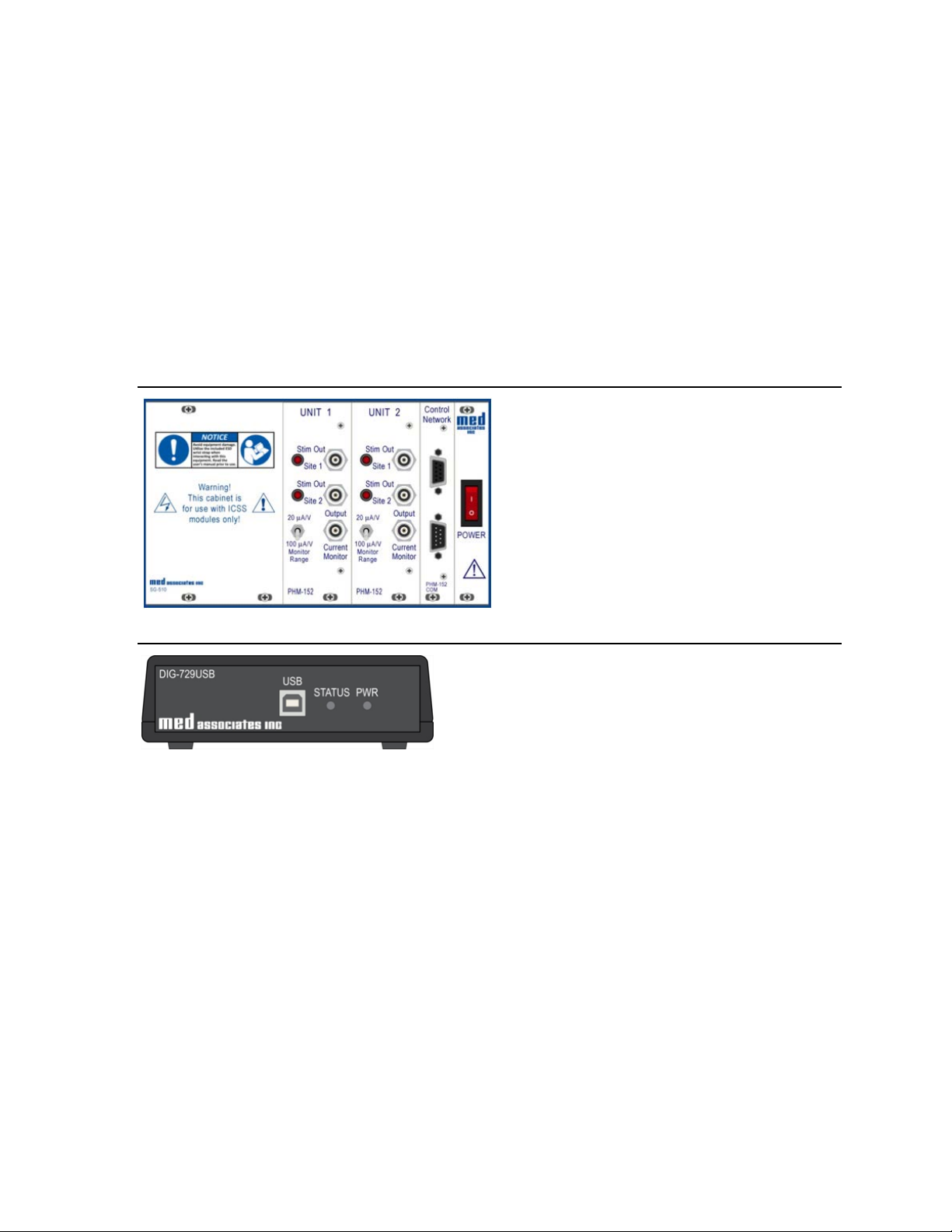
The PHM-15x system will include stimulator(s) and a PHM-152-COM Control Network card installed in
an SG-510 Interface Cabinet as shown in Figure 2.2 below. The system utilizes a DIG-729USB Interface
shown in Figure 2.3 below.
Figure 2.2 - SG-510 Cabinet with Stimulators and Control Network Card
Figure 2.3 - DIG-729USB
- 3 - DOC-012 Rev. 2.3 Copyright © 2019
Med Associates, Inc.
MED ASSOCIATES, INC.
PHM-15X ICSS STIMULATOR
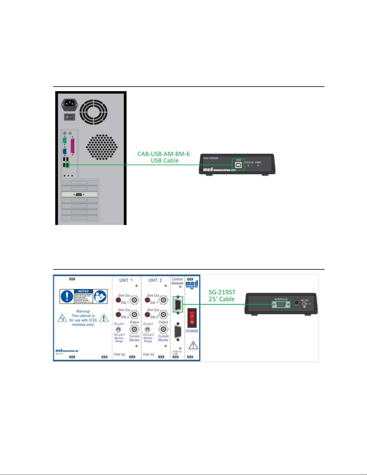
Wiring Instructions
1. Using the included USB cable, connect the USB port on the computer to the USB port on the DIG-
729USB as shown in Figure 2.4 below.
Figure 2.4 - Connect the Computer USB Port to the DIG-729USB
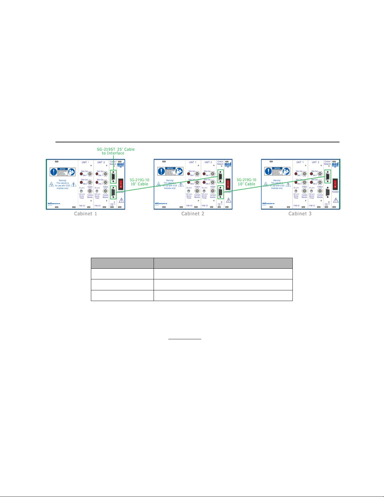
2. Using the SG-219ST (25’) cable, connect the male DB-15 INTERFACE connector on the DIG-729USB
to the female DB-9 connector on the Control Network (PHM-152 COM) card as shown in Figure 2.5
below.
Figure 2.5 - Connect the Control Network Card to the DIG-729USB
- 4 - DOC-012 Rev. 2.3 Copyright © 2019
Med Associates, Inc.
MED ASSOCIATES, INC.
PHM-15X ICSS STIMULATOR
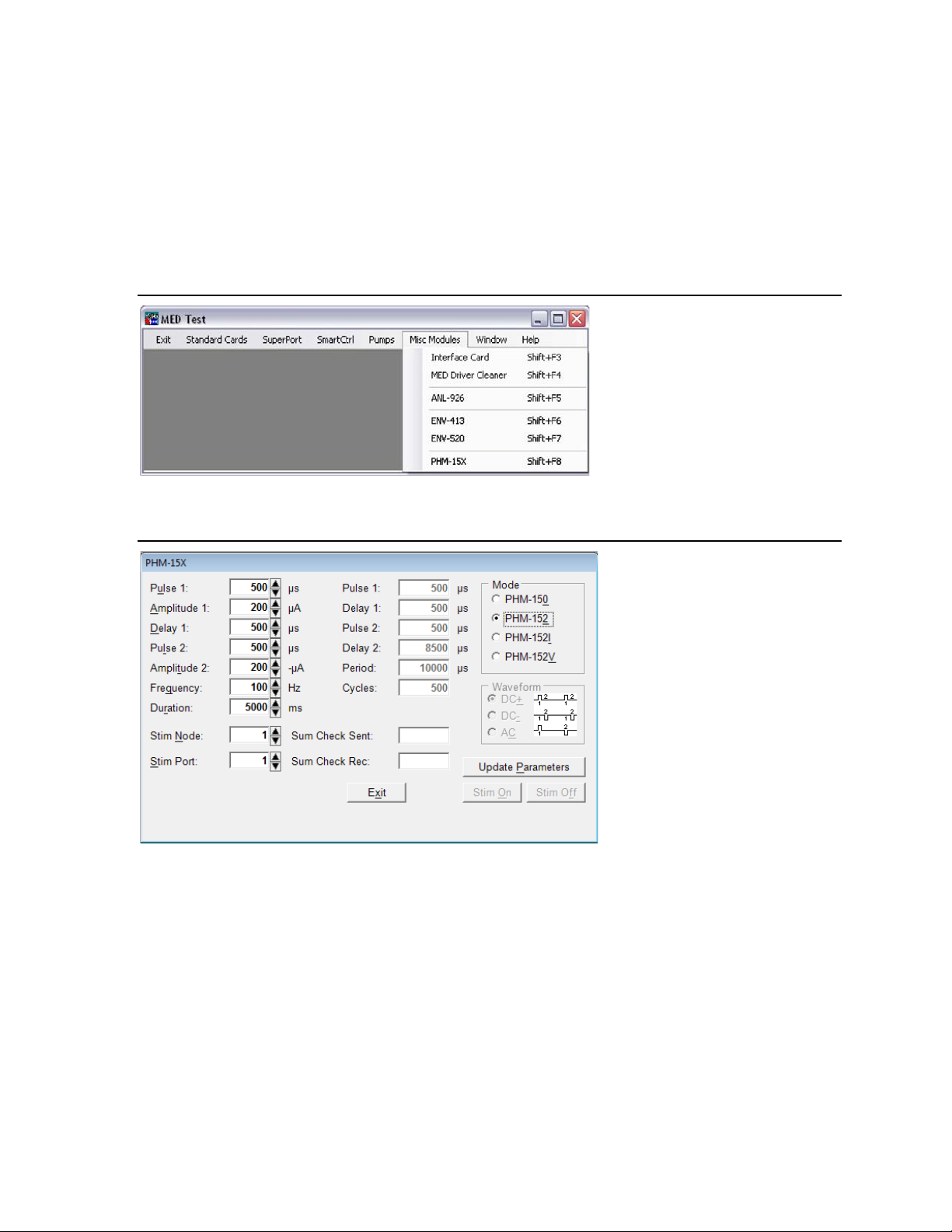
Connecting Additional Cabinets
To connect a second cabinet, use an SG-219G-10 (10’) cable to connect the male DB-9 connector on the
Control Network (PHM-152 COM) card in the first cabinet to the female DB-9 connector on the Control
Network (PHM-152 COM) card in the second cabinet. Continue daisy-chaining cabinets in this fashion
using the SG-219G-10 (10’) cables until the last cabinet in the chain is reached as shown in Figure 2.6
below. Up to eight cabinets (16 stimulator cards) can be daisy chained to a single interface.
It is important that the cable lengths mentioned above are used. If the cable lengths are exceeded,
equipment malfunction may occur.
Figure 2.6 - Daisy Chaining Cabinets
Stimulator Output
Output from the stimulator is via a standard BNC connector. Med Associates offers several cables and
adapters:
Part Number Description
PHM-155A 5’ BNC to BNC Cable
PHM-155B 10’ BNC to BNC Cable
PHM-155C Female BNC to Female Banana Adapter
Viewing the Constant Current Output with an Oscilloscope
When attempting to use an oscilloscope to temporarily view the constant current (square wave) output
waveform from either the Site 1 or Site 2 connectors for verification of proper operation, it is important
to remember that the output is a current waveform, not voltage. To view the waveform from Site 1 for
instance, a ‘load’ resistor must be placed across the Site 1 BNC connector. A 10K Ohm (1/2 Watt rated)
substitution load resistor works well for this purpose. The voltage across the substitution load resistor
will be related to the current delivered using the following equation:
Current (microamps) = (Peak Voltage (Volts) / Resistance (Ohms))*1,000,000
The Site 1 and Site 2 output waveforms can be viewed with an Input channel of the oscilloscope
connected across the Stim Out load resistor. Med Associates can provide a 10K Ohm substitution
resistor, Part # PHM-152SC-10K, that allows a convenient interconnection between the Stim Out BNC
connector and the input channel BNC connector on the oscilloscope. If using a 2-channel oscilloscope,
- 5 - DOC-012 Rev. 2.3 Copyright © 2019
Med Associates, Inc.

MED ASSOCIATES, INC.
PHM-15X ICSS STIMULATOR
Channel 2 can be connected – temporarily – across the substitution load resistor and Channel 1 can be
connected to the Current Monitor Output – continuously – as described in the Viewing the Waveform
Using the Current Monitor Output with an Oscilloscope on Page 6. In this way the user can confirm that
both outputs – Stim and Current Monitor – are able to produce a proper output when the Stim Out Site
is actively connected to the implant electrodes.
The connection of an oscilloscope to a Stim Out connector, as described above, should only be
temporary. Continuous monitoring of the Stim Output pulse train with an oscilloscope or data
acquisition equipment should be done via the Current Monitor Output.
Viewing the Waveform Using the Current Monitor Output with an Oscilloscope
The waveform produced at the Current Monitor Output connector is a voltage representation of the
constant current flowing through the Site 1 or Site 2 load (either the test subject or the 10K Ohm
substitution resistor discussed above). To view the waveform from the Current Monitor BNC connector,
the load resistor (as described above) or a subject via electrodes must be connected to either the Site 1
or Site 2 connector.
Connect a Male-BNC to Male-BNC patch cable from the Current Monitor Output connector to a channel
of an oscilloscope. This output is ground-referenced so the measurement does not need to be made
differentially.
When the stimulator is producing a current waveform through the subject, the voltage representation of
the current will be shown on the scope connected to the Current Monitor Output.
The Sensitivity Range switch allows the user to scale the monitor waveform to show either 20 µA/V (1
Volt of vertical deflection on the oscilloscope for each 20 µA of current flow) or 100 µA/V (1 Volt of
vertical deflection on the oscilloscope for each 100 µA of current flow).
For instance, if the Sensitivity Range switch is set to the 20µA/V range and Current Monitor waveform
shows a 5-Volt peak signal, then the peak current through the subject should be 100 µA.
- 6 - DOC-012 Rev. 2.3 Copyright © 2019
Med Associates, Inc.

MED ASSOCIATES, INC.
PHM-15X ICSS STIMULATOR
CHAPTER 3 | SAFETY LOCK-OUT
Output Monitor Safety Lock-Out Protection
The signal output of each Stimulus generating channel is continuously monitored for harmful levels of
DC current that could be passed to the stimulus site.
During the generation of an active pulse-train, each output channel will check for the presence of an all-
negative or all positively oriented signals that could cause harm to the test animal. In the event of such
an occurrence, the output amp of that channel will spontaneously shut down to a lock-out state.
The occurrence of an error event of this nature can be the result of a hardware failure caused by
exposure to static electricity. Also, the state can be induced by incorrect pulse-train parameters that
send an all-negative or all-positive going signal at the highest current settings.
The safety lock-out event is marked by both of the “Stim-out” site LEDs flashing simultaneously. When
this happens, the main cabinet must be powered off to reboot the channel that is flashing the error. If
the effected channel returns to the lock-out state after multiple attempts to reset, this is an indication
that the channel has developed a hardware problem and must be returned for repair to Med Associates.
- 7 - DOC-012 Rev. 2.3 Copyright © 2019
Med Associates, Inc.
MED ASSOCIATES, INC.
PHM-15X ICSS STIMULATOR
CHAPTER 4 | TESTING THE HARDWARE
Running MED Test
To run MED Test, click Start on the Windows®taskbar, then All Programs > MED Associates > MED Test,
then the MED Test application. Once MED Test is open, select Misc Modules > PHM-15X. Refer to
Figure 4.1 below.
Figure 4.1 - MED Test Menu
For testing PHM-150B or PHM-152 units, select PHM-152 in the Mode Box. Refer to Figure 4.2 below.
Figure 4.2 - PHM-15X MED Test Form
Nine Waveform Parameters governing the stimulus pulse train are displayed with default values on the
left side of the screen as indicated.
Each parameter may be changed within the range specified in the Operating Parameters list given in
Table 4.1 shown below. However, they are not mutually exclusive (i.e. Pulse and Delay values must be
compatible with Duration and Frequency values.) Error messages will appear when incompatible values
are selected.
- 8 - DOC-012 Rev. 2.3 Copyright © 2019
Med Associates, Inc.
MED ASSOCIATES, INC.
PHM-15X ICSS STIMULATOR
Waveform Parameters
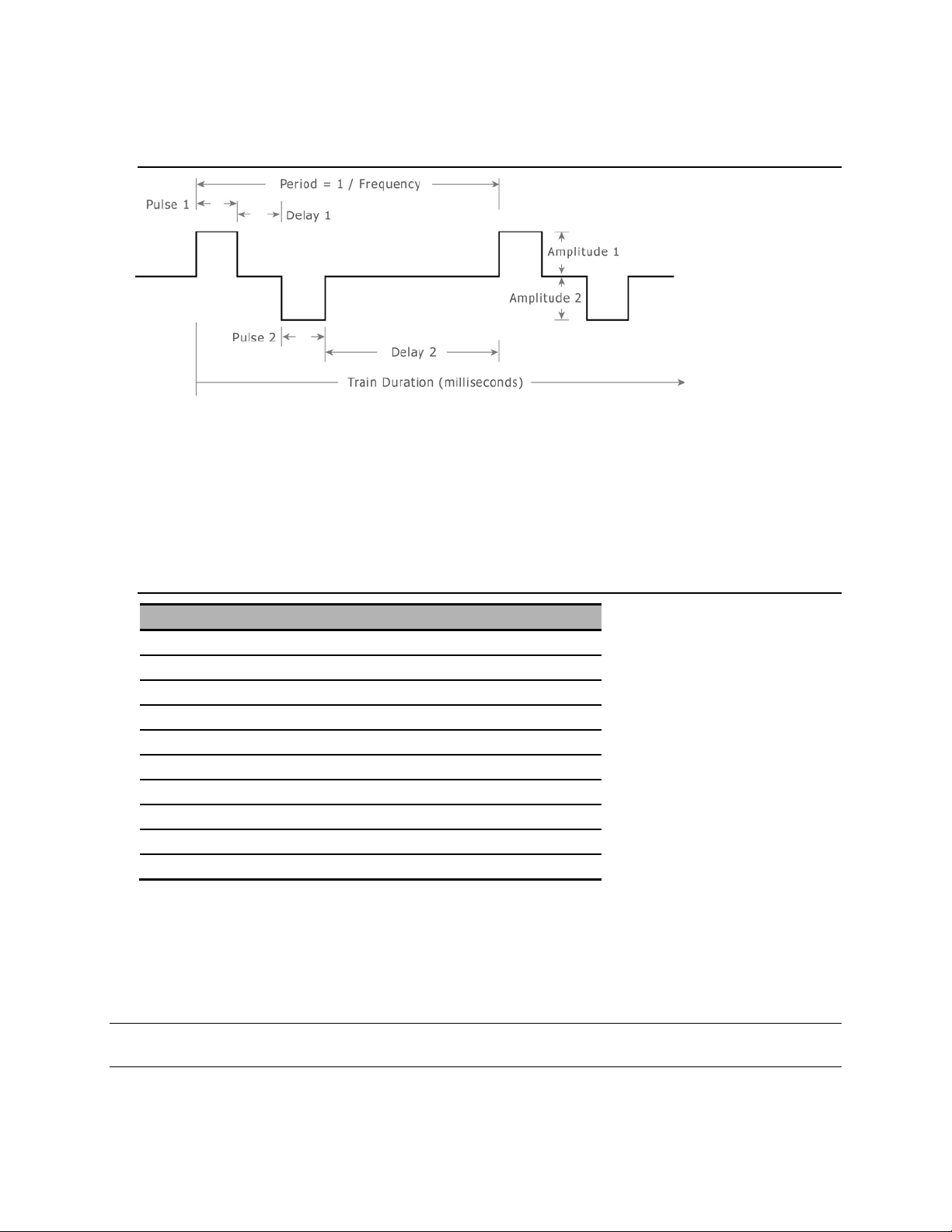
Figure 4.3 - Sample Waveform with Two Pulse Pairs in the Train
The waveform shown in Figure 4.3 above illustrates two complete cycles. Each cycle is made up of a
positive pulse (Pulse 1), a delay (Delay 1), a negative pulse (Pulse 2) and a second delay (Delay 2). All
these parameters including the period (time between cycles) and the total ON time duration of the
waveform are user programmable. See Table 4.1 below for minimum and maximum operating
parameters.
Table 4.1 - Operating Parameters
Description Default Value Allowable Range
Pulse 1 500 µs 60 – 32,000 µs
Amplitude 1 200 µA 0 – 1000 µA
Delay 1 500 µs 60 – 32,000 µs
Pulse 2 500 µs 60 – 32,000 µs
Amplitude 2 200 µA 0 – 1000 µA
Delay 2 (*1) 60 – 500,000 µs
Frequency 100 Hz 1 – 2000 Hz (*2)
Duration 5000 ms (*3)
Stim Node 1 1 – 16 (*4)
Stim Port 1 1 – 2 (*4)
(*1) Not directly adjustable.
Automatically set by the formula (1,000,000 / Frequency) – (Pulse 1 + Delay 1 + Pulse 2).
(*2) Limited by the Pulse and Delay parameters.
(*3) Must permit a minimum of one cycle.
(*4) Must correspond with module setting.
NOTE 4: Period is the total time for one cycle or the sum (Pulse 1 + Delay 1 + Pulse 2 + Delay 2).
- 9 - DOC-012 Rev. 2.3 Copyright © 2019
Med Associates, Inc.

MED ASSOCIATES, INC.
PHM-15X ICSS STIMULATOR
Activating the Stimulator
Once the desired parameters have been selected, they must be sent to the Stimulator hardware. Click
on the "Update Parameters" button to do this. A number should appear in the "Sum Check Sent" box. If
communication was successful, the "Sum Check Rec" box should contain the same number. If the "Sum
Check Rec" box contains a different number, check the hardware connections and node values (see,
Setting the Node Values, page 2).
- 10 - DOC-012 Rev. 2.3 Copyright © 2019
Med Associates, Inc.

MED ASSOCIATES, INC.
PHM-15X ICSS STIMULATOR
CHAPTER 5 | CONTROLLING STIMULATORS IN MED-PC®
The PHM-150B/PHM-152 is compatible with MED-PC®Version 2.08 and higher. Because the stimulator
commands STIMULATE, STIMON, and STIMOFF are passed as a Pascal procedure they must be enclosed
in tildes (~). Also note that the semicolon line terminator inside the tilde is required. This does not
replace the semicolon used to separate multiple commands in the same statement as required in
MedState NotationTM.
STIMULATE
The STIMULATE command sets up all stimulus parameters for the stimulator and retains them until
changed or power is turned OFF. It is not necessary to issue a STIMULATE command each time the
stimulator is turned ON.
Syntax: ~Stimulate(MG, P1, P2, P3, P4, P5, P6, P7, P8);~
Where: MG = The MED-PC Global Parameter.
P1 = The Stim Node value (1 to 16).
P2 = The Width of Pulse 1 (60 to 32,000 µs).
P3 = The Amplitude of Pulse 1 (1 to 1000 µA).
P4 = The Delay between Pulse 1 & Pulse 2 (60 to 32,000 µs).
P5 = The Width of Pulse 2 (60 to 32,000 µs).
P6 = The Amplitude of Pulse 2 (1 to 1000 µA).
P7 = Frequency (1 to 2000 Hz).
P8 = Duration in milliseconds.
NOTE 5: P1 through P8 may be numbers, variables, or array variables. Array variables must be
expressed using square brackets P[1], not the normal parenthesis ( ) used in MedState NotationTM.
- 11 - DOC-012 Rev. 2.3 Copyright © 2019
Med Associates, Inc.

MED ASSOCIATES, INC.
PHM-15X ICSS STIMULATOR
STIMON
The STIMON command selects the output port and turns the stimulator ON. Allow at least one clock tick
between the STIMULATE command and the STIMON command (i.e. do not place both commands in the
same State.)
Syntax: ~StimOn(MG, P1, P2);~
Where: MG = The MED-PC Global Parameter.
P1 =The Stim Node value (1 to 16).
P2 = The Stim Port to turn ON (1 or 2).
NOTE 6: P1 and P2 may be numbers, variables, or array variables. Array variables must be expressed
using square brackets P[1], not the normal parenthesis ( ) used in MedState NotationTM.
STIMOFF
STIMOFF is identical to STIMON and may be used to terminate a stimulus train prior to the duration
setting. Since most pulse trains are quite short this command is seldom used. For extended periods of
stimulation, however, it would be possible to set duration for some maximum value and actually turn
stimulation ON and OFF with these two commands.
Syntax: ~StimOff(MG, P1, P2);~
Where: MG = The MED-PC Global Parameter.
P1 =The Stim Node value (1 to 16).
P2 = The Stim Port to turn OFF (1 or 2).
NOTE 7: P1 and P2 may be numbers, variables, or array variables. Array variables must be expressed
using square brackets P[1], not the normal parenthesis ( ) used in MedState NotationTM.
- 12 - DOC-012 Rev. 2.3 Copyright © 2019
Med Associates, Inc.

MED ASSOCIATES, INC.
PHM-15X ICSS STIMULATOR
STIMTEST.MPC Sample MedState NotationTM Program
The STIMTEST.MPC sample protocol shown below is included on the PHM-15X installation disk.
\ Copyright (C) 2016 MED Associates, All rights reserved.
\ STIMTEST.MPC
\ This program demonstrates how to properly call the MED-PC commands that start
\ and stop the PHM-15X Stimulators.
\ When the program is loaded it will set up the default values and then wait for
\ the START command.
\ When the START command is received the program will send the selected values
\ down to the Stimulator. The program will now wait for a response on either
\ the Left or Right Lever.
\ If a Left Lever response is received, then the program will turn on Port 1
\ (Stim Site 1) on the stimulator at the selected values.
\ If a Right Lever response is received, then the program will turn on Port 2
\ (Stim Site 2) on the stimulator at the selected values.
\ A K1 pulse will turn off the Stimulator and exit the program.
\ Stimulate - Sets up the stimulation parameters for the stimulator.
\ StimOn - This command selects the output port and turns the stimulator ON.
\ Allow at least one clock tick between the Stimulate command and
\ the StimOn command (i.e. do not place both commands in the same
\ State.)
\ StimOff - Used to stop a stimulation prior to the end of the pre-established
\ duration setting.
\ MG - This is the MED-PC Global Pointer. It allows the PHM-15X to pass back
\ information about any errors that might have occured.
\ BOX - This parameter specifies which PHM-15X the command is for. When this
\ program is running in Box 1, then the BOX parameter will equal 1 and the
\ PHM-15X that is set to Node 1 will receive the command. When this
\ program is running in Box 2, then the BOX parameter will equal 2 and the
\ PHM-15X that is set to Node 2 will receive the command, etc. This
\ allows the same program to be run in multiple Boxes and control the
\ different Chambers.
\ Inputs
^LeftLever = 1
^RightLever = 2
\ Outputs
^LeftLever = 1
^RightLever = 2
^Pellet = 3
^Dipper = 3 \ If both Pellet and Dipper are ordered
\ It will be necessary to change one of these
^LeftLight = 4
^RightLight = 5
^HouseLight = 7
^Pump = 8
- 13 - DOC-012 Rev. 2.3 Copyright © 2019
Med Associates, Inc.

MED ASSOCIATES, INC.
PHM-15X ICSS STIMULATOR
\ A() = Control Variables with Assigned Aliases as Defined
Var_Alias Pulse 1 Width (us) = A(0) \ Default = 500 us
Var_Alias Pulse 1 Amplitude (uA) = A(1) \ Default = 200 uA
Var_Alias Delay between Pulse 1 and 2 (us) = A(2) \ Default = 500 us
Var_Alias Pulse 2 Width (us) = A(3) \ Default = 500 us
Var_Alias Pulse 2 Amplitude (uA) = A(4) \ Default = 200 uA
Var_Alias Frequency (Hz) = A(5) \ Default = 100 Hz
Var_Alias Duration (ms) = A(6) \ Default = 5000 ms
^Width1 = 0
^Amp1 = 1
^Delay = 2
^Width2 = 3
^Amp2 = 4
^Frequency = 5
^Duration = 6
\ List Working Variables Here
\ H = Stimulation Duration in MED Ticks
DIM A = 6
\ K-Pulses Used in this Program
\ K1 = Turn off the Stimulator and exit the program
\***************************************************
\ STIMTEST Schedule
\ S1 - Set Default Values
\ Pulse 1 Width (500 us)
\ Pulse 1 Amplitude (200 uA)
\ Delay between Pulse 1 and 2 (500 us)
\ Pulse 2 Width (500 us)
\ Pulse 2 Amplitude (200 uA)
\ Frequency (100 Hz)
\ Duration (5000 ms)
\***************************************************
S.S.1,
S1,
0.01": SET A(^Width1) = 500, A(^Amp1) = 200, A(^Delay) = 500;
SET A(^Width2) = 500, A(^Amp2) = 200, A(^Frequency) = 100;
SET A(^Duration) = 5000 ---> S2
S2,
#START: ---> S3
1": SHOW 1,Width 1,A(^Width1), 2,Amp 1,A(^Amp1), 3,Delay,A(^Delay);
SHOW 4,Width 2,A(^Width2), 5,Amp 2,A(^Amp2), 6,Freq,A(^Frequency);
SHOW 7,Duration,A(^Duration) ---> S2
S3, \ Send the values to the Stimulator
0.01": ~Stimulate(MG, BOX, A[0], A[1], A[2], A[3], A[4], A[5], A[6]);~;
SET H = A(^Duration) / 1000 * 1" ---> S4
S4, \ Wait for command to turn Stimulator On
#R^LeftLever: ~StimOn(MG, BOX, 1);~ ---> S5
#R^RightLever: ~StimOn(MG, BOX, 2);~ ---> S5
S5, \ Make sure the User can't send another StimOn
\ command while the Stimulator is running.
H#T: ---> S3
- 14 - DOC-012 Rev. 2.3 Copyright © 2019
Med Associates, Inc.

MED ASSOCIATES, INC.
PHM-15X ICSS STIMULATOR
\***************************************************
\ KILL ROUTINE
\***************************************************
S.S.2,
S1,
#K1: ~StimOff(MG, BOX, 1);~ ---> S2
S2,
0.01": ~StimOff(MG, BOX, 2);~ ---> STOPKILL
\***************************************************
\ SHOW PARAMETER VALUES
\***************************************************
S.S.3,
S1,
#START: ---> S2
S2,
1": SHOW 1,Width 1,A(^Width1), 2,Amp 1,A(^Amp1), 3,Delay,A(^Delay);
SHOW 4,Width 2,A(^Width2), 5,Amp 2,A(^Amp2), 6,Freq,A(^Frequency);
SHOW 7,Duration,A(^Duration) ---> S2
Examples Using STIMULATE and STIMON
The following examples are functionally equivalent. Brain stimulation reward is used as the
reinforcement for an FR-10 schedule. 80 µA pulses, 200 µs in width (100µs delay) are delivered for 0.5
seconds at a frequency of 125 Hz.
Example A:
S.S.1,
S1,
0.01": ~Stimulate(MG, BOX, 200, 80, 100, 200, 80, 125, 500);~ ---> S2
S2,
10#R1: ~StimOn(MG, BOX, 1);~ ---> S2
Example B:
LIST P = 0, 200, 80, 100, 200, 80, 125, 500
S.S.1,
S1,
0.01": SET P(0) = BOX;
~Stimulate(MG,P[0],P[1],P[2],P[3],P[4],P[5],P[6],P[7]);~ ---> S2
S2,
10#R1: ~StimOn(MG, P[0], 1);~ ---> S2
- 15 - DOC-012 Rev. 2.3 Copyright © 2019
Med Associates, Inc.

MED ASSOCIATES, INC.
PHM-15X ICSS STIMULATOR
APPENDIX A | SOFTWARE INSTALLATION
Programs written in MedState NotationTM must be translated and compiled before they can be executed
in MED-PC®. A copy of the protocol is present in the MED-PC®installation directory, for example,
“C:\MED-PC\MPC\”, after the PHM-15X software installation program has been run.
To translate and compile the protocols, refer to the MED-PC®Programmer’s Manual. On the computer
running MED-PC®, open the Windows®Start menu, select All Programs > MED Associates > MED-PC >
Manuals to access the Programmer’s Manual.
APPENDIX B | CONTACT INFORMATION
Please contact Med Associates, Inc. for information regarding any of our products.
For Technical questions, email support@med-associates.com.
For Sales questions, email sales@med-associates.com.
Visit our website at www.med-associates.com.
- 16 - DOC-012 Rev. 2.3 Copyright © 2019
Med Associates, Inc.
This manual suits for next models
7
Table of contents
Other MED Associates Medical Equipment manuals


Popular Medical Equipment manuals by other brands


Roche
Roche ACCU-CHEK TenderLink Instructions for use

Direct Supply
Direct Supply Panacea PAN-PL5500DF owner's manual

Cellink
Cellink Inkredible+ user manual

KOELIS
KOELIS Trinity Transport full pack user manual

Arjo
Arjo Dual-Loop Attachment Straps Instructions for use

Aspen Medical Products
Aspen Medical Products Vista quick start guide