MEDIATEK Genio 1200 User manual

MediaTek Proprietary and Confidential. © 2022 MediaTek Inc. All rights reserved.
Unauthori ed reproduction or disclosure of this document, in whole or in part, is strictly prohibited.
Use of this document and any information contained therein is subject to the terms and conditions set forth in Exhibit 1. This document
is subject to change without notice.
Version: 0.1
Release date: 2023-05-26
Genio 1200 Evaluation Kit
User Guide

MediaTek Proprietary and Confidential. © 2022 MediaTek Inc. All rights reserved. Unauthori ed reproduction or disclosure of this document, in whole or in part, is strictly prohibited.
2
Genio 1200 EVK
Genio 1200 Evaluation Kit User Guide
Version History
Version Date uthor Description
0.1 2023-05-26 MediaTek Draft Release

MediaTek Proprietary and Confidential. © 2022 MediaTek Inc. All rights reserved. Unauthori ed reproduction or disclosure of this document, in whole or in part, is strictly prohibited.
3
Genio 1200 EVK
Genio 1200 Evaluation Kit User Guide
Table of Contents
Version History ································································································································································· 2
Table of Contents ····························································································································································· 3
List of Figures ··································································································································································· 4
List of Tables ····································································································································································· 5
1 Overview ·································································································································································· 6
1.1 General Information ················································································································································· 6
1.2 Architecture and Block Diagram ······························································································································· 6
1.3 Feature Summary ····················································································································································· 7
2 Introduction ····························································································································································· 8
2.1 CPU (MT8395IV/ZA) ··············································································································································· 11
2.2 Power Management IC (MT6365IAW/B) ················································································································ 11
2.3 DRAM (Micron MT53E1G32D2FW-046 IT:B) ·········································································································· 12
2.4 eMMC Storage (Western Digital SDINBDG4-64G-XI2) ···························································································· 12
2.5 UFS Storage (Micron MTFC64GASAONS-IT) ··········································································································· 12
2.6 M.2 Wi-Fi/Bluetooth Module (A ureWave AW-XB468NF) ····················································································· 12
2.7 M.2 5G Module (Quectel_RM500K-CN) - Planning, Schedule: 2023/Q4 ······························································· 12
2.8 How to Power Up the System ································································································································· 13
2.9 EVK Debug ······························································································································································ 14
2.10 How to Switch Boot from eMMC to UFS ················································································································ 16
3 Interface and Connectors ········································································································································ 18
3.1 Genio 1200 EVK I/O Connectors ····························································································································· 18
3.2 System Power Paths ··············································································································································· 19
3.2.1 System Power ·············································································································································· 19
3.2.2 Auto Power On ············································································································································ 20
3.3 I/O Interface ··························································································································································· 20
3.4 Micro SD Card Connector ······································································································································· 23
3.5 Power and Function Key Interface ························································································································· 23
3.6 USB Device ····························································································································································· 23
3.7 USB Host ································································································································································· 23
3.8 Audio Interface ······················································································································································· 24
3.9 Microphones ·························································································································································· 24
3.10 MIPI DSI Interface ··················································································································································· 25
3.11 MIPI CSI Interface ··················································································································································· 25
3.12 Ethernet Interface ·················································································································································· 25
3.13 How to Switch between eDP and LVDS Panel ········································································································ 26
3.14 HDMI Port······························································································································································· 27
3.15 Antenna Connector ················································································································································ 28
3.16 Pin Mux for Other Interface ··································································································································· 28
4 Camera Daughter Board ········································································································································· 30
4.1 D2 Camera Daughter Board ··································································································································· 30
4.1.1 Key Feature and Block Diagram ·················································································································· 31
4.2 D6 Camera Daughter Board ··································································································································· 31
4.2.1 Key Feature and Block Diagram ·················································································································· 32

MediaTek Proprietary and Confidential. © 2022 MediaTek Inc. All rights reserved. Unauthori ed reproduction or disclosure of this document, in whole or in part, is strictly prohibited.
4
Genio 1200 EVK
Genio 1200 Evaluation Kit User Guide
4.2.2 Configure D6 Camera DTB ··························································································································· 32
4.2.3 D6 Camera DTB Optional Function ············································································································· 33
5 Power Distribution ················································································································································· 35
5.1 Power Distribution ················································································································································· 35
6 Software ································································································································································ 36
6.1 Android ··································································································································································· 36
6.1.1 Android Software Project and Configuration ······························································································ 36
6.1.2 How to Get Android Software Image ·········································································································· 36
6.1.3 Android Software Image Flash Method ······································································································ 36
6.2 Yocto ······································································································································································· 38
6.2.1 Yocto Software Project and Configuration ·································································································· 38
6.2.2 How to get Yocto Software Image ··············································································································· 38
6.2.3 Yocto Software Image Flash Method ·········································································································· 38
6.3 How to switch Android Image and Yocto Image ····································································································· 39
7 ppendix ································································································································································ 40
7.1 The Reason Why Camera Icon Disappears on Home Screen and How to Resolve It ·············································· 40
Exhibit 1 Terms and Conditions ······································································································································· 41
List of Figures
Figure 1-1 Genio 1200 Evaluation Kit System Block Diagram ····································································································· 6
Figure 2-1 Genio 1200 EVK System Setup ·································································································································· 8
Figure 2-2 Genio 1200 EVK Top View ········································································································································· 9
Figure 2-3 Genio 1200 EVK Bottom View ································································································································· 10
Figure 2-4 Power Up the System ·············································································································································· 13
Figure 2-5 Console Screen ························································································································································ 13
Figure 2-6 Debug Port ······························································································································································ 14
Figure 2-7 Putty Example ························································································································································· 14
Figure 2-8 Log Screen ······························································································································································· 15
Figure 2-9 Boot on Strapping Path ··········································································································································· 16
Figure 2-10 Flash Tool Format Screen ······································································································································ 16
Figure 2-11 Flash Tool Download Screen ································································································································· 17
Figure 3-1 System Power Path ·················································································································································· 20
Figure 3-2 Microphone Placement ··········································································································································· 24
Figure 3-3 Antenna Connectors ··············································································································································· 28
Figure 4-1 D2 Camera DTB ······················································································································································· 30
Figure 4-2 Block Diagram of D2 Camera DTB ··························································································································· 31
Figure 4-3 D6 Camera DTB ······················································································································································· 31
Figure 4-4 Block Diagram of D6 Camera DTB ··························································································································· 32
Figure 5-1 Power Distribution ·················································································································································· 35
Figure 6-1 Flash Tool Window ·················································································································································· 37
Figure 6-2 Download Port ························································································································································ 37
Figure 7-1 Factory Reset ··························································································································································· 40

MediaTek Proprietary and Confidential. © 2022 MediaTek Inc. All rights reserved. Unauthori ed reproduction or disclosure of this document, in whole or in part, is strictly prohibited.
5
Genio 1200 EVK
Genio 1200 Evaluation Kit User Guide
List of Tables
Table 2-1 Contains in the Box ··················································································································································· 10
Table 2-2 Key Component List ·················································································································································· 11
Table 2-3 Boot Initiation (SW5) ················································································································································ 16
Table 2-4 SW5 Pin Status ·························································································································································· 16
Table 3-1 Main Board Connectors ············································································································································ 18
Table 3-2 Power Paths (J50 and J44) ········································································································································ 19
Table 3-3 Auto Power On (J51) ················································································································································· 20
Table 3-4 LED Indicators ··························································································································································· 20
Table 3-5 UART Ports (J34 and J52) ·········································································································································· 21
Table 3-6 I2C Bus ······································································································································································ 21
Table 3-7 Pin Assignments of the Raspberry Pi Like I/O Pin Header ························································································ 22
Table 3-8 USB Feature in Genio 1200 EVK ································································································································ 23
Table 3-9 Microphones Location ·············································································································································· 24
Table 3-10 Ethernet LED Indicator ············································································································································ 25
Table 3-11 Panel Switch (J49) ··················································································································································· 26
Table 3-12 Pin Mux for eDP and LVDS Interface ······················································································································· 26
Table 3-13 On-Board Antenna ·················································································································································· 28
Table 3-14 Other Interface (J43) ··············································································································································· 28
Table 3-15 Pin Mux Controlled by Setting Jumper J43 Open or Short ····················································································· 29
Table 4-1 Camera Configure (CAM Connector) ························································································································ 30
Table 4-2 Configure D6 Camera DTB ········································································································································ 32
Table 4-3 Optional Function of D6 Camera DTB ······················································································································· 33
Table 6-1 Android Project Name and Configuration ················································································································ 36

MediaTek Proprietary and Confidential. © 2022 MediaTek Inc. All rights reserved. Unauthori ed reproduction or disclosure of this document, in whole or in part, is strictly prohibited.
6
Genio 1200 EVK
Genio 1200 Evaluation Kit User Guide
1Overview
1.1 General Information
Genio 1200 EVK is an evaluation kit of MediaTek MT8395 platform, integrated with Wi-Fi/Bluetooth (M.2 Module)
and 5G/GPS (M.2 Module), which is a high performance IoT platform with rich features.
Note: Genio 1200 EVK is only for development and evaluation, please follow the "MT8395 Baseband Design Notice"
document for hardware design rules.
1.2 rchitecture and Block Diagram
Figure 1-1 Genio 1200 Evaluation Kit System Block Diagram

MediaTek Proprietary and Confidential. © 2022 MediaTek Inc. All rights reserved. Unauthori ed reproduction or disclosure of this document, in whole or in part, is strictly prohibited.
7
Genio 1200 EVK
Genio 1200 Evaluation Kit User Guide
1.3 Feature Summary
MediaTek CPU (MT8395IV/ZA)
MediaTek PMIC (MT6365IAW/B)
4GB LPDDR4X RAM x 2 (Micron MT53E1G32D2FW-046 IT:B)
64GB eMMC x 1 (Western Digital SDINBDG4-64G-XI2)
Φ2.0 DC Jack x 1 (for 12V DC Input)
Micro SD Card Connector x 1
Push Button x 4 (Power, Reset, Home and Download)
LED x 3 (System Power, Reset, DC-IN Power)
4-Lane MIPI DSI x 2
4-Lane MIPI CSI x 3
HDMI x 2 (IN x 1, OUT x 1)
LVDS x 1
eDP x 1
10/100/1000M Ethernet x 1 (Realtek RTL8211FI-CG)
Micro USB x 2 (device, UART)
•UART Port for Trace Log with USB to UART Bridge IC
USB Type-A 3.2 Connector x 2
USB Type-C Connector (USB 3.2/DP MUX)
3.5mm Earphone Jack x 1 (with Microphone Input)
3.5mm Line Out Audio Jack x 1
Analog Microphone x 3 (Merry MMA102-006)
Digital Microphone x 2 (Merry MMA102-007)
UART Port x 1 (6 PIN/2.54mm Pin Header)
M.2 Slot Key E x 1
•For A ureWave AW-XB468NF Wi-Fi 6 & BT 5.2 Module
M.2 Slot Key B x 1
•For Quectel RM500K-CN 5G Sub-6 Module
40-Pin 2.54mm Pin Header x 1 (for Raspberry Pi Like I/O Interface)
Micro SIM x 1
Nano SIM x 1
Operating Temperature: -40°C ~ 85°C
MediaTek Proprietary and Confidential. © 2022 MediaTek Inc. All rights reserved. Unauthori ed reproduction or disclosure of this document, in whole or in part, is strictly prohibited.
8
Genio 1200 EVK
Genio 1200 Evaluation Kit User Guide
2Introduction
Genio 1200 EVK board integrates MediaTek MT8395 processor, 64bit LPDDR4X memory, eMMC, UFS, Power Management
IC (MT6365), Wi-Fi/BT M.2 Module and 5G M.2 Module.
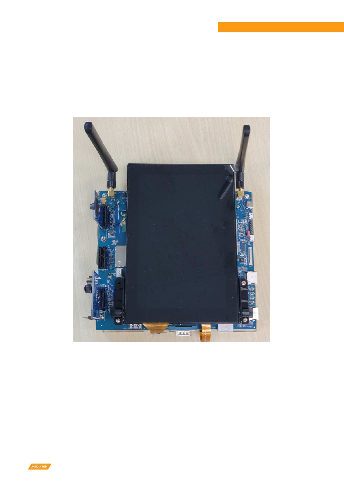
The package contains a Genio 1200 EVK main board, MIPI DSI 7” LCD panel, one Wi-Fi 6 module and two camera daughter
boards.
Figure 2-1 Genio 1200 EVK System Setup

MediaTek Proprietary and Confidential. © 2022 MediaTek Inc. All rights reserved. Unauthori ed reproduction or disclosure of this document, in whole or in part, is strictly prohibited.
9
Genio 1200 EVK
Genio 1200 Evaluation Kit User Guide
Figure 2-2 Genio 1200 EVK Top Vie
RJ-45
Connector
CAN FD
Connector
Raspberry Pi Like
Connector
Earphone
Connector
Speaker
Connector
DC IN
Jack
Battery
Connector
Wi-Fi ANT1
Connector
Wi-Fi ANT2
Connector
Wi-Fi ANT3
Connector
Camera CAM2
Connector
Camera CAM1
Connector
Camera CAM0
Connector
USB 3.2
Connector
HDMI RX
Connector
Download Key
M.2 Connector for
MT7921 Wi-Fi Module
HDMI TX
Connector
UART 0 Debug
Connector
Micro USB
Connector
UART 1 Debug
Connector
USB Type-C
Connector
Power Key
Reset Key
Home Key
eDP Connector
eMMC / UFS
Switch
MediaTek Proprietary and Confidential. © 2022 MediaTek Inc. All rights reserved. Unauthori ed reproduction or disclosure of this document, in whole or in part, is strictly prohibited.
10
Genio 1200 EVK
Genio 1200 Evaluation Kit User Guide
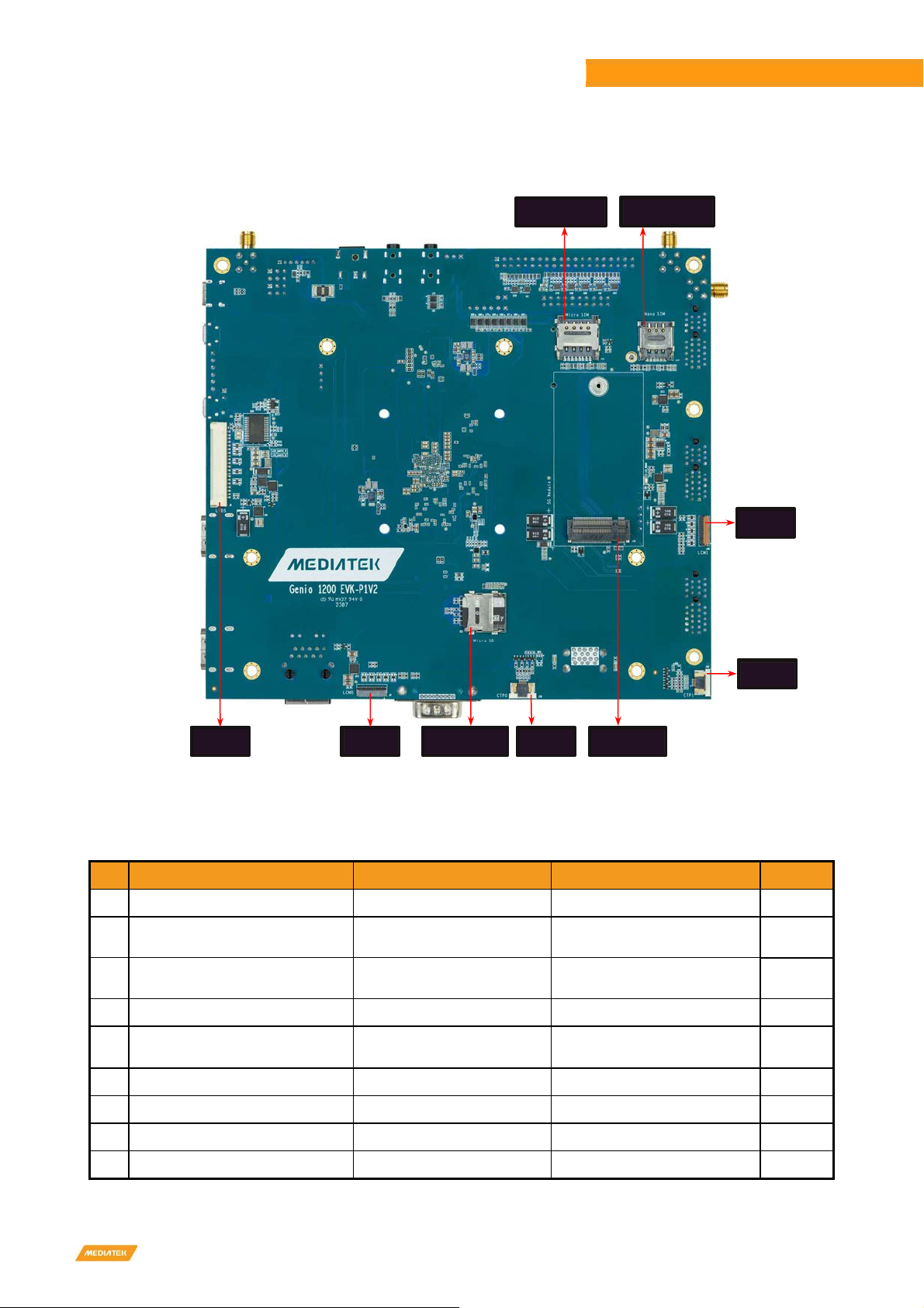
Figure 2-3 Genio 1200 EVK Bottom Vie
Table 2-1 Contains in the Box
S.No
Part Number or Marketing Item Name Description Quantity
1 Genio 1200 EVK-P1V2 Genio 1200 EVK Main Board
1
2 IoT-CAM-DTB-D1V2-D2 D2 Camera Board Camera Daughter Board Using
IMX214 Image Sensor 1
3 IoT-CAM-DTB-D1V3-D6 D6 Camera Board Camera Daughter Board Using
AR0830 Image Sensor 1
4 KD070FHFID078-01-C021A 7” LCD Panel LCM Module 1
5 M.2 Wi-Fi 6 module
AW-XB468NF (IC: MT7921L) Wi-Fi Module Installed 1
6 IPEX to IPEX cable-158mm Installed on Mainboard 1
7 IPEX to IPEX cable-50mm Installed on Mainboard 1
8 SMA antenna Wi-Fi Antenna 2
9 12V AC adaptor + power cord 1
Micro SIM Card
Connector
Nano SIM Card
Connector
LVDS
Connector
LCM1
Connector
CTP1
Connector
M.2 Connector for
5G Module
Micro SD Card
Connector
CTP0
Connector
LCM0
Connector

MediaTek Proprietary and Confidential. © 2022 MediaTek Inc. All rights reserved. Unauthori ed reproduction or disclosure of this document, in whole or in part, is strictly prohibited.
11
Genio 1200 EVK
Genio 1200 Evaluation Kit User Guide
Table 2-2 Key Component List
Function Manufacturer PN
Baseband Processor
MediaTek MT8395IV/ZA
Main PMIC MediaTek MT6365IAW/B
Sub PMIC MediaTek MT6360PP
Buck MediaTek MT6315LP/B, MT6315GP/B, MT6691SVP/A
LDO MediaTek MT6680P/A
Memory Micron MT53E1G32D2FW-046 IT:B
eMMC Western Digital SDINBDG4-64G-XI2
UFS Micron MTFC64GASAONS-IT
Camera Module MediaTek IoT-CAM-DTB-D1V2-D2, IoT-CAM-DTB-D1V3-D6
Connectivity A ureWave AW-XB468NF (MT7921L Module)
Ethernet PHY Realtek RTL8211FI-CG
2.1 CPU (MT8395IV/Z )
MediaTek Genio 1200 processor is a highly integrated platform incorporating the following key features:
•Quad-Core ARM® Cortex-A78 processor
•Quad-Core ARM® Cortex-A55 processor
•Arm Mali-D57 MC5 3D Graphics Accelerator (GPU) with Vulkan 1.1, OpenGL ES 3.2 and OpenCL 2.2
•Dual-core AI Processor Unit (APU) Cadence® Tensilica®
•VP6 processor with AI Accelerator (AIA)
•Single-core Cadence HiFi 4 Audio Engine DSP
•LPDDR4X: Up to 16GB, with memory data rate up to LPDDR4X-4266
•Display output supporting 4K60 + 4K60 resolution
•Image processing: 48MP @ 30fps for single camera capture; 16MP +16MP @ 30fps for dual camera capture
•Video encoding: 4K @ 60 fps with HEVC/H.264
•Video decoding: 4K @ 90 fps with AV1/VP9/HEVC/H.264
2.2 Power Management IC (MT6365I W/B)
MediaTek MT6365 power management IC is a programmable power management IC that integrates 9 buck converters and
33 LDOs to provide all power rails required by SoC and peripherals.
MT6365 adopts the SPI interface and two SRCLKEN control pins to control buck converters, LDOs, and various drivers; it
provides enhanced safety control and protocol for handshaking with the processor MT8395.
For system management, it provides the following features,
•9 buck converters and 33 LDOs
•Precision voltage, temperature, and current measurement fuel gauge
•26MH external crystal for system clock
•32.768KH RTC oscillator for system timing
•Watchdog reset
•Over-current and thermal overload protection
•OVP, UVLO function
•WFBGA-203 package

MediaTek Proprietary and Confidential. © 2022 MediaTek Inc. All rights reserved. Unauthori ed reproduction or disclosure of this document, in whole or in part, is strictly prohibited.
12
Genio 1200 EVK
Genio 1200 Evaluation Kit User Guide
2.3 DR M (Micron MT53E1G32D2FW-046 IT:B)
Genio 1200 EVK has two 4GB LPDDR4X memory with the following features.
•Dual Channels with 16-bit Data Bus Width
•Supports self-refresh/ partial self-refresh mode
•Supports dual-rank memory device
2.4 eMMC Storage (Western Digital SDINBDG4-64G-XI2)
A 64GB eMMC 5.1 SDINBDG4-64G-XI2 of Western Digital is used for code and data storage, via MSDC0 interface of the
baseband processor MT8395 with 8-bit width data bus.
2.5 UFS Storage (Micron MTFC64G S ONS-IT)
A 64GB UFS MTFC64GASAONS-IT of Micron is used for code and data storage, which can be switched by the switch SW5 on
the EVK. Please refer to chapter 2.10.
2.6 M.2 Wi-Fi/Bluetooth Module ( zureWave W-XB468NF)
MediaTek MT7921 is designed inside A ureWave AW-XB468NF M.2 Module. It supports following features.
•M.2 2230 Wi-Fi Module with Key A-E
•MediaTek MT7921L Wi-Fi Chip
•PCIe/USB Interface
•Wi-Fi 802.11 a/b/g/n/ac/ax
•Dual Band 2T/2R MIMO
•Bluetooth 5.2
•Security WFA WPA/WPA2/WPA3 Personal, WPS 2.0, WAPI
•Integrated LNA, PA and T/R Switch
2.7 M.2 5G Module (Quectel_RM500K-CN) - Planning, Schedule: 2023/Q4
MediaTek Genio 1200 EVK supports Quectel RM500K-CN M.2 Module, which has following features:
• M.2 Key B WWAN
• USB 3.0/USB 2.0
• Dual SIM Single Standby (Micro SIM x 1 + nano SIM x 1)
• 5G NR SA support n1/n28/n41/n78/n79
• 5G NR NSA support n41/n78/n79
• LTE-FDD support B1/B3/B5/B8/B28
• LTE-TDD support B34/B39/B40/B41
• WCDMA support B1/B8
• GNSS support GPS/GLONASS/BeiDou (COMPASS)/Galileo/QZSS
MediaTek Proprietary and Confidential. © 2022 MediaTek Inc. All rights reserved. Unauthori ed reproduction or disclosure of this document, in whole or in part, is strictly prohibited.
13
Genio 1200 EVK
Genio 1200 Evaluation Kit User Guide
2.8 How to Power Up the System
Power on the Genio 1200 EVK board by following steps.
Step1: Must install camera daughter board (DTB) on C M0 or C M2 connector.
(If camera app without in Android desktop, please refer to chapter 7 Appendix of Genio 1200 EVK User Guide for fixed it)
Step2: Connect UART0 to the computer via a micro-USB cable (If you want to see the logs).
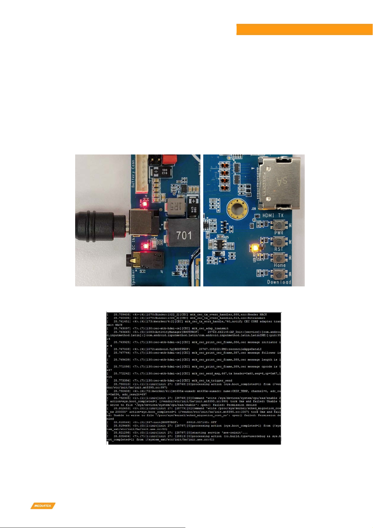
Step3: Plug in the DC 12V power adapter.
Step4: Long press PWR button more than 3 seconds.
You will see the screen is shown on MIPI DSI display and some trace logs come out from UART0.
Figure 2-4 Po er Up the System
Figure 2-5 Console Screen
Note: If you want to use the camera APP, please make sure to plug in the D2/D6 camera daughter board before power up
the EVK.
MediaTek Proprietary and Confidential. © 2022 MediaTek Inc. All rights reserved. Unauthori ed reproduction or disclosure of this document, in whole or in part, is strictly prohibited.
14
Genio 1200 EVK
Genio 1200 Evaluation Kit User Guide
2.9 EVK Debug
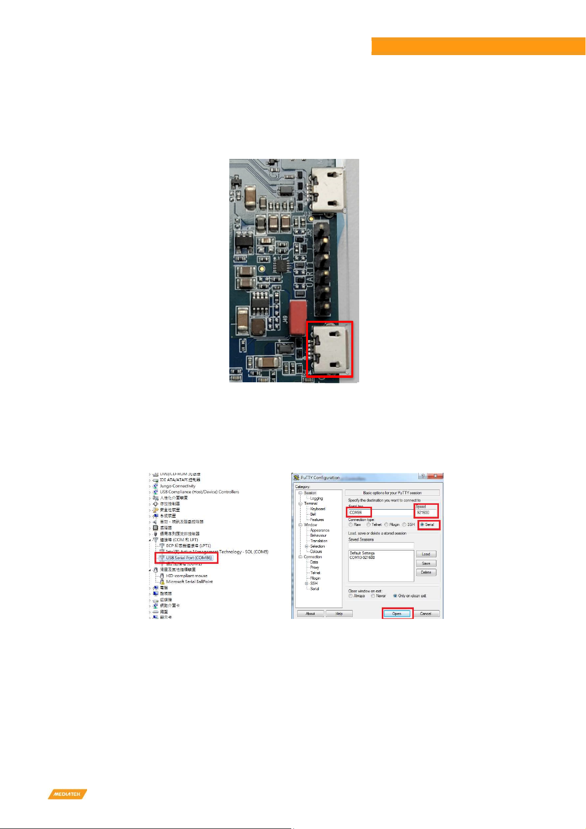
•Micro USB (J34) output UART log
•Please install FT232RL driver
Figure 2-6 Debug Port
•Check PC USB port could be recogni ed the UART device
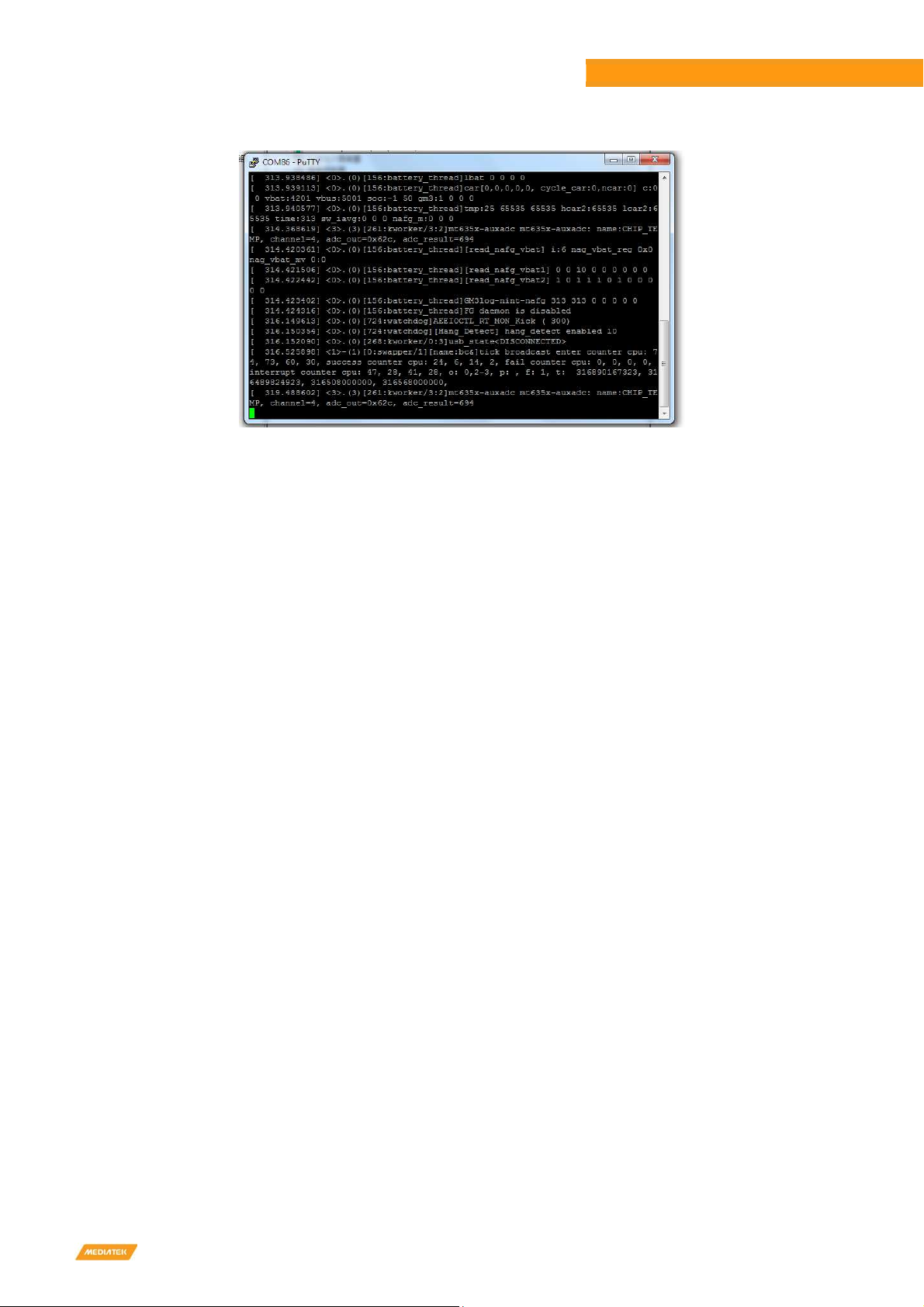
•Setting “serial line” (ex. COM86), “speed” to 921600, choose “connection type” to serial and press “Open” on PuTTY
for log (Example on PuTTY)
Figure 2-7 Putty Example
MediaTek Proprietary and Confidential. © 2022 MediaTek Inc. All rights reserved. Unauthori ed reproduction or disclosure of this document, in whole or in part, is strictly prohibited.
15
Genio 1200 EVK
Genio 1200 Evaluation Kit User Guide
Figure 2-8 Log Screen
Install the "MTK USB cable driver (Driver_Auto_Installer_EXE. ip)" and "Universal ADB driver
(UniversalAdbDriverSetup. ip)" into your Windows 10 host machine

MediaTek Proprietary and Confidential. © 2022 MediaTek Inc. All rights reserved. Unauthori ed reproduction or disclosure of this document, in whole or in part, is strictly prohibited.
16
Genio 1200 EVK
Genio 1200 Evaluation Kit User Guide
2.10 How to Switch Boot from eMMC to UFS
You can choose to boot from eMMC or boot from UFS by switching the state of SW5.
Table 2-3 Boot Initiation (SW5)
Boot from eMMC Boot from UFS
1: ON, 2: OFF (Default) 1: OFF, 2: ON
Table 2-4 SW5 Pin Status
UD_SYNC_MOSI UD_CLK_MOSE Storage Booting SW5
L H (by external PU) Only eMMC boot 1: ON, 2: OFF (Default)
L L Only UFS boot 1: OFF, 2: ON
Figure 2-9 Boot on Strapping Path
1.Power off the EVK, then switch DIP (SW5) to eMMC boot: Run "SP Flash Tool", on <Format> tab, press <Start> button
to format eMMC. Then plug the USB Type-C cable to EVK. It will format eMMC partition automatically.
Figure 2-10 Flash Tool Format Screen

MediaTek Proprietary and Confidential. © 2022 MediaTek Inc. All rights reserved. Unauthori ed reproduction or disclosure of this document, in whole or in part, is strictly prohibited.
17
Genio 1200 EVK
Genio 1200 Evaluation Kit User Guide
2. Power off the EVK, then switch DIP (SW5) to UFS boot: Run "SP Flash Tool", on <Download> tab, choose <Format All +
Download> in combo box, and then press <Download> to flash image to UFS partition.
Figure 2-11 Flash Tool Do nload Screen
3. After flashing finished, remove the USB Type-C cable and reboot system.
Note: Choose “Format All + Download”, if MAC address were set previously, after this action MAC address will be format.

MediaTek Proprietary and Confidential. © 2022 MediaTek Inc. All rights reserved. Unauthori ed reproduction or disclosure of this document, in whole or in part, is strictly prohibited.
18
Genio 1200 EVK
Genio 1200 Evaluation Kit User Guide
3Interface and Connectors
3.1 Genio 1200 EVK I/O Connectors
Table 3-1 Main Board Connectors
Description Location Note
Battery Connector J1
DC Jack J2
DC-IN Power On Indicator LED 11 Red LED
System Power On Indicator LED 1 Red LED
Reset Indicator LED10 Yellow LED
Power On Button SW1
Reset Button SW2
Home Button SW3
Download Button SW4
Boot Switch SW5 Switch between eMMC and UFS
USB 3.2 J10 Dual USB Type-A 3.2 x 2
USB 3.2 Type-C J12 USB 3.2 Port / DP Display Port (MUX)
USB 2.0 J13 Micro USB
UART0 J34 Debug (Core Processor Log)
UART1 J52 Debug (SCP Log)
Micro SD Card Connector SD1
LCM0 Connector J4 7” MIPI DSI Panel (DSI 0)
LCM1 Connector J40 7” MIPI DSI Panel (DSI 1)
CTP0 Connector J39 7” Touch
CTP1 Connector J42 7” Touch
eDP Connector J8 17.3” eDP Panel
LVDS Connector J6 LVDS Panel
CAM0 Connector J30 MIPI CSI0 A/B Interface
CAM1 Connector J31 MIPI CSI0 C/D Interface
CAM2 Connector J32 MIPI CSI1 A/B Interface
Nano SIM Card Connector J14
Micro SIM Card Connector J15
M.2 3052 Key B Slot J18 RM500K-CN 5G Module
Wi-Fi Antenna (Aux) J21
Wi-Fi Antenna (main) J23
Wi-Fi Antenna (main spare) J25
M.2 2230 Key E Slot J26 AW-XB468NF(MT7921L) Wi-Fi Module
Ethernet J27
HDMI TX J28 HDMI Out
HDMI RX J29 HDMI In
Raspberry Pi Like I/O J33

MediaTek Proprietary and Confidential. © 2022 MediaTek Inc. All rights reserved. Unauthori ed reproduction or disclosure of this document, in whole or in part, is strictly prohibited.
19
Genio 1200 EVK
Genio 1200 Evaluation Kit User Guide
JTAG J35
SPI Flash Connector J38
CAN FD J45
Earphone Jack J46
Line Out J47
CH7513 EEPROM Connector J48
eDP/LVDS Switch Jumper J49
Auto Power On Jumper J51
FAN Connector FAN1
3.2 System Power Paths
3.2.1 System Power
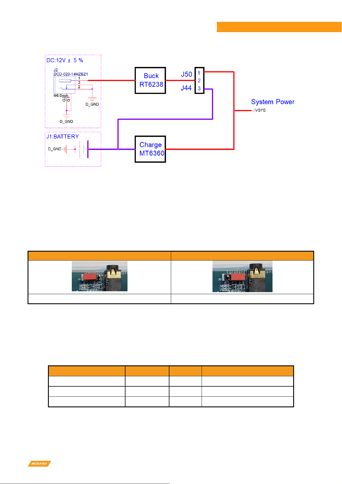
There are three power supply paths for the system. DC adaptor supply have two paths connect 12V DC adaptor, a buck
converter (Richtek RT6238), which convert 12V (DC Jack) to 4.2V output. The 4.2V output connect two jumpers.
The first path is to short the jumper J50, the 4.2V output is connected to VSYS.
The second path is to short the jumper J44, the 4.2V output is connected to the charger IC (MediaTek MT6360), and then
connected to VSYS through the charger IC.
Note: DO NOT connect the battery in the second path.
The third path is battery power (not verified), the battery power is connected to the charger IC (MediaTek MT6360), and
then connected to VSYS through the charger IC. This path supports those applications using Li-polymer batteries.
Table 3-2 Po er Paths (J50 and J44)
Power Path DC to VSYS Power Path DC to VB T
J50 short 1-2, short 3-4, short 5-6(default) J44 short 1-2, short 3-4, short 5-6
MediaTek Proprietary and Confidential. © 2022 MediaTek Inc. All rights reserved. Unauthori ed reproduction or disclosure of this document, in whole or in part, is strictly prohibited.
20
Genio 1200 EVK
Genio 1200 Evaluation Kit User Guide
Figure 3-1 System Po er Path
3.2.2 uto Power On
The Genio 1200 EVK supports system power on when adapter is plugged in. You need to change the J51 jumper to switch
the power on mode.
If you need to use "auto power on" function, please ask MediaTek for a patch.
Table 3-3 Auto Po er On (J51)
Manual Power On uto Power On
J51 short 1-2(default) J51 short 2-3
3.3 I/O Interface
LED Indicators
There are three LED indicators.
Table 3-4 LED Indicators
LED Indicators Location Color Note
DC-IN Power Indicator LED 11 Red LED is on if adaptor is on
Reset Indicator LED10 Yellow LED is off if reset signal is low
System Power Indicator LED 1 Red LED is on while 12V to 5V complete
Other manuals for Genio 1200
1
Table of contents
Other MEDIATEK Motherboard manuals

MEDIATEK
MEDIATEK Genio 510 User manual

MEDIATEK
MEDIATEK Genio 1200 User manual

MEDIATEK
MEDIATEK Genio 700 Installation manual

MEDIATEK
MEDIATEK Genio 350 User manual

MEDIATEK
MEDIATEK Genio 700 EVK User manual

MEDIATEK
MEDIATEK MT7612 User manual

MEDIATEK
MEDIATEK LinkIt Smart 7688 Specification sheet

MEDIATEK
MEDIATEK LinkIt 7697 HDK User manual

MEDIATEK
MEDIATEK Genio 350 Installation manual

MEDIATEK
MEDIATEK Genio 700 EVK User manual


