MEDIATEK LinkIt Smart 7688 Instruction Manual

© 2015 MediaTek Inc.
This document contains information that is proprietary to MediaTek Inc.
Unauthorized reproduction of this information in whole or in part is strictly prohibited.
MediaTek LinkIt™ Smart 7688
Developer's Guide
Version: 0.92 Beta
Release date: November 2015
Specifications are subject to change without notice.

MediaTek LinkIt™ Smart 7688 Developer's Guide
© 2015, 2016 MediaTek Inc.
Page 2 o
This document contains information that is proprietary to MediaTek Inc.
Unauthorized reproduction or disclosure of this information in whole or in part is strictly prohibited.
Document Revision History
Revision
Date
Description
0.91 November 2015 •LED status diagram,
•COM port INF driver for Windows 8 and 10,
•Pip/npm installation for Python and Node.js
•mDNS on virtual machine
0.92 November 23, 2015 •Revised Web UI
•File system & opkg test case pass
•Basic behavior test

MediaTek LinkIt™ Smart 7688 Developer's Guide
© 2015, 2016 MediaTek Inc.
Page 3 o
This document contains information that is proprietary to MediaTek Inc.
Unauthorized reproduction or disclosure of this information in whole or in part is strictly prohibited.
Table of contents
1. Introduction ..................................................................................................................................................... 7
1.1. What is MediaTek LinkIt? ................................................................................................................................ 7
1.2. What is MediaTek LinkIt Smart 7688 Development Platform ...................................................... 7
1.3. Hardware Development Kits......................................................................................................................... 7
1.4. Programming Environment........................................................................................................................... 7
1.5. Software Development Kit ............................................................................................................................ 7
1.6. Get Started.............................................................................................................................................................8
1.7. More Information................................................................................................................................................8
1.8. Join the MediaTek Labs Ecosystem ...........................................................................................................9
2. Hardware Development Kit ..................................................................................................................... 10
2.1. MediaTek MT7688AN Chip Specification Summary......................................................................... 10
2.2. LinkIt Smart 7688 .............................................................................................................................................. 11
2.3. LinkIt Smart 7688 Duo.................................................................................................................................... 19
2.4. FCC, CE and NCC Certifications ................................................................................................................. 26
3. Programming Environment Guide.........................................................................................................27
3.1. Platform operating system..........................................................................................................................27
3.2. Programming Environment Overview ....................................................................................................27
3.3. Programming Model for Different Boards........................................................................................... 28
3.4. Choosing the right programming model .............................................................................................. 29
3.5. Network Environment ................................................................................................................................... 29
3.6. Programming in C/C++.................................................................................................................................. 30
3.7. Programming in Python..................................................................................................................................31
3.8. Programming in Node.js ................................................................................................................................32
4. Software Development Kit and related tools.................................................................................. 34
4.1. Software Development Kit ......................................................................................................................... 34
4.2. Supported Host Environments ................................................................................................................. 34
4.3. Default OpenWrt Packages ........................................................................................................................ 34
4.4. OPKG Packager Manager ..............................................................................................................................35
4.5. System Configuration.................................................................................................................................... 36
4.6. System configuration tasks........................................................................................................................ 45
4.7. File Editor and Transfer .................................................................................................................................53
5. Peripheral Programming on LinkIt Smart 7688 .............................................................................. 59
5.1. How to Access LinkIt Smart 7688 Peripheral using MRAA .......................................................... 59
5.2. How to use UPM to access sensors and peripherals ...................................................................... 66
6. Peripheral Programming on LinkIt Smart 7688 Duo ..................................................................... 68
6.1. Installing Arduino IDE .................................................................................................................................... 68
6.2. Installing Board Support Package ........................................................................................................... 68
6.3. Installing LinkIt Smart 7688 Duo COM Port Driver............................................................................72
6.4. Programming model for LinkIt Smart 7688 Duo ...............................................................................73
6.5. Programming with Primitive UART Connection.................................................................................76
6.6. Programming with Firmata Protocol ......................................................................................................78
6.7. Programming with Yun Bridge Library...................................................................................................90
7. Troubleshooting Guide............................................................................................................................. 92
7.1. My firmware upgrade won’t start or failed. Why? ............................................................................ 92
7.2. I can’t connect to URL mylinkit.local using a browser, why is that?........................................ 92
7.3. My virtual machine cannot detect the board when in Station mode, why? ........................ 92
7.4. I’m not able to SSH access with an error showing “Host Identification Has Changed”,
what can I do?.................................................................................................................................................... 93

MediaTek LinkIt™ Smart 7688 Developer's Guide
© 2015, 2016 MediaTek Inc.
Page 4 o
This document contains information that is proprietary to MediaTek Inc.
Unauthorized reproduction or disclosure of this information in whole or in part is strictly prohibited.
7.5. There are multiple LinkIt Smart 7688 APs nearby and I’m not sure which one is mine,
how do I find out?............................................................................................................................................. 94
7.6. My board seems to have stopped working, what do I do?............................................................ 94
Appendix A................................................................................................................................................................ 96

MediaTek LinkIt™ Smart 7688 Developer's Guide
© 2015, 2016 MediaTek Inc.
Page 5 o
This document contains information that is proprietary to MediaTek Inc.
Unauthorized reproduction or disclosure of this information in whole or in part is strictly prohibited.
Lists of tables and figures
Table 1 MT7688AN SOC Specification.............................................................................................................................10
Table 2 LinkIt Smart 7688 Development board buttons....................................................................................... 12
Table 3 Wi-Fi LED blink pattern in LinkIt Smart 7688 HDK ................................................................................... 13
Table 4 Typical power consumption scenarios ..........................................................................................................14
Table 5 LinkIt Smart 7688 development boards specifications..........................................................................17
Table 6 LinkIt Smart 7688 Duo Development board buttons ............................................................................. 21
Table 7 Peripherals Power Consumption..................................................................................................................... 22
Table 8 LinkIt Smart 7688 Duo development board specifications................................................................24
Table 9 LinkIt Smart 7688 Programming Environment Overview................................................................... 28
Table 10 OS Capabilities .......................................................................................................................................................34
Table 11 Packaged included in the LinkIt Smart 7688 development platform........................................... 35
Table 12 Configuration functions of the Web UI and System console ........................................................... 36
Table 13 USB and LinkIt Smart 7688 UART Pin Mapping.......................................................................................42
Table 14 Wi-Fi AP Encryption Type................................................................................................................................... 51
Table 15 File Transfer Tools................................................................................................................................................ 53
Table 16 LinkIt Smart 7688 GPIO Pin Mapping ...........................................................................................................60
Table 17 MCU and MPU Communication ....................................................................................................................... 76
Table 18 Serial Pin Mapping Between MPU and MCU ............................................................................................. 78
Figure 1 LinkIt Smart 7688 development board (MPU only) .................................................................................. 11
Figure 2 Removing resistor to enable I-PEX connector ......................................................................................... 13
Figure 3 USB OTG cable .........................................................................................................................................................14
Figure 4 JTAG resistors on the bottom of the LinkIt Smart 7688...................................................................... 15
Figure 5 Moving a resistor to access JTAG mode ...................................................................................................... 15
Figure 6 LinkIt Smart 7688 Pin-out Diagram...............................................................................................................18
Figure 7 LinkIt Smart 7688 Duo development board (MPU + MCU) .................................................................20
Figure 8 JTAG resistors on LinkIt Smart 7688 Duo bottom view ...................................................................... 22
Figure 9 Moving a resistor to access JTAG mode ..................................................................................................... 23
Figure 10 LinkIt Smart 7688 Duo Pin-out Diagram .................................................................................................. 25
Figure 11 Programming models for the LinkIt Smart 7688 development platform.................................28
Figure 12 LinkIt Smart 7688 in AP Mode........................................................................................................................ 29
Figure 13 LinkIt Smart 7688 in Station Mode..............................................................................................................30
Figure 14 Connecting LinkIt Smart development board to a computer .........................................................37
Figure 15 Wi-Fi LED Status ..................................................................................................................................................38
Figure 16 Connecting to LinkIt Smart 7688 AP ..........................................................................................................38
Figure 17 LinkIt Smart 7688 in AP mode........................................................................................................................ 39
Figure 18 LinkIt Smart 7688 Web UI Sign In ................................................................................................................. 39
Figure 19 Using SSH in Windows PuTTY........................................................................................................................40
Figure 20 PuTTY Security Warning ..................................................................................................................................41

MediaTek LinkIt™ Smart 7688 Developer's Guide
© 2015, 2016 MediaTek Inc.
Page 6 o
This document contains information that is proprietary to MediaTek Inc.
Unauthorized reproduction or disclosure of this information in whole or in part is strictly prohibited.
Figure 21 System Console.....................................................................................................................................................41
Figure 22 LinkIt Smart 7688 COM port using Serial to USB cable ....................................................................43
Figure 23 Using UART to USB cable to access system console in Windows terminal............................44
Figure 24 Firmware upgrade button ..............................................................................................................................46
Figure 25 Selecting firmware file.....................................................................................................................................46
Figure 26 Firmware version ................................................................................................................................................ 47
Figure 27 Wi-Fi LED Status During Firmware Upgrade .......................................................................................... 47
Figure 28 Factory Reset using LinkIt Smart 7688 Web UI....................................................................................48
Figure 29 Change networking setting in Web UI.......................................................................................................49
Figure 30 Changing to Station mode in Web UI ........................................................................................................50
Figure 31 LinkIt Smart 7688 in Station mode connected to a Wi-Fi AP........................................................... 51
Figure 32 System Information in LinkIt Smart 7688 Web UI............................................................................... 52
Figure 33 SCP Security Warning ....................................................................................................................................... 53
Figure 34 WinSCP login window .......................................................................................................................................54
Figure 35 File transfer using WinSCP.............................................................................................................................54
Figure 36 File transfer confirmation .............................................................................................................................. 55
Figure 37 File transfer using Samba in Windows.......................................................................................................57
Figure 38 Connecting to LinkIt Smart 7688 from Finder.......................................................................................57
Figure 39 Connecting to mylinkit.local server in Mac ............................................................................................58
Figure 40 Connecting as guest to mylinkit.local on Mac......................................................................................58
Figure 41 MyShareFolder in Mac Finder ........................................................................................................................58
Figure 42 LinkIt Smart 7688 Software Architecture...............................................................................................59
Figure 43 Set up the Node.js application prompt.....................................................................................................65
Figure 44 LinkIt Smart 7688 Duo Hardware Architecture....................................................................................68
Figure 45 LinkIt Smart 7688 package URL for a custom board installation in Arduino IDE.................69
Figure 46 Arduino IDE Board Manager Menu .............................................................................................................69
Figure 47 LinkIt Smart 7688 Board Package Menu.................................................................................................. 70
Figure 48 LinkIt Smart 7688 board package installed on Arduino IDE ............................................................71
Figure 49 LinkIt Smart 7688 Duo installed on Arduino IDE ..................................................................................72
Figure 50 Arduino Preference Location.........................................................................................................................73
Figure 51 Driver installation.................................................................................................................................................73
Figure 52 LinkIt Smart 7688 Duo Hardware Architecture.................................................................................... 74
Figure 53 Software architecture ...................................................................................................................................... 74
Figure 54 Firmata Protocol..................................................................................................................................................75
Figure 55 Yun Bridge Library ...............................................................................................................................................75
Figure 56 Upload Sketch in Arduino IDE ........................................................................................................................77
Figure 57 MPU MCU Communication Diagram .......................................................................................................... 79
Figure 58Copying example code from Github...........................................................................................................83
Figure 59 Uploading example sketch in Arduino IDE .............................................................................................84
Figure 60 Programming boot loader using AVRDUDE ..........................................................................................90
Figure 61 Finding LinkIt Smart 7688 IP address in Station mode...................................................................... 92
Figure 62 Host ID change warning................................................................................................................................... 93
Figure 63 Known hosts file.................................................................................................................................................. 93
Figure 64 Finding LinkIt Smart 7688 hardware address .......................................................................................94

MediaTek LinkIt™ Smart 7688 Developer's Guide
© 2015, 2016 MediaTek Inc.
Page 7 o
This document contains information that is proprietary to MediaTek Inc.
Unauthorized reproduction or disclosure of this information in whole or in part is strictly prohibited.
1. Introduction
This section provide an overview of the MediaTek LinkIt™ development platforms and introduction
to the MediaTek LinkIt Smart 7688 development platform, which also acts as a guide to the
content of this document.
1.1. What is MediaTek LinkIt?
MediaTek LinkIt™ is a collection of development platforms designed for the prototyping of
Wearables and Internet of Things (IoT) devices. Each development platforms provide a collection
of tools, hardware and related resources to enable developers to address one of the three
Wearables and Internet of Things (IoT) device sectors. (Figure to be provided).
1.2. What is MediaTek LinkIt Smart 7688 Development Platform
The MediaTek LinkIt Smart 7688 is a Linux Wi-Fi SOC development board designed to enable the
prototyping of IoT devices. These devices include Wi-Fi security web cam and sensors for the
home or office, real time camera monitor for toddler and seniors as well as cloud-based
applications.
LinkIt Smart 7688 is an open development platform based on the OpenWrt Linux distribution. The
platform provides generous memory and storage to enable rich application developments. The
platform also offers options to create device applications using Python, Node.js or C.
During prototyping the platform can take advantage of the free MediaTek Cloud Sandbox service
to store data in the cloud. And the MediaTek Labs Partner Connect program is available to help
get devices to market.
1.3. Hardware Development Kits
The LinkIt Smart 7688 development platform offers two development boards:
•LinkIt Smart 7688: MPU only. Powered by MediaTek MT7688.
•LinkIt Smart 7688 Duo: MPU and MCU. Powered by MT7688 and ATmega32U4.
For more details on the development boards, please see Chapter 2, “Development boards”.
1.4. Programming Environment
The LinkIt Smart 7688 development platform supports high-level languages (Python and Node.js)
and native application development (C). In addition, the MCU on the LinkIt Smart 7688 Duo can
programmed using the Arduino API and tools.
For more details on the software development options, please see Chapter 3, “Programming
Environment Guide”.
1.5. Software Development Kit
LinkIt Smart 7688 offers a Software Development Kit with tools and utilities for tasks such as
configuring the development boards, updating board firmware, board support manager and
installing software.

MediaTek LinkIt™ Smart 7688 Developer's Guide
© 2015, 2016 MediaTek Inc.
Page 8 o
This document contains information that is proprietary to MediaTek Inc.
Unauthorized reproduction or disclosure of this information in whole or in part is strictly prohibited.
For more details on the tools and utilities provided, please see Chapter 4, “Software Development
Kit and related tools”.
1.6. Get Started
You can find the LinkIt Smart 7688 Get Started guide on MediaTek Lab’s website and learn how to
run a blink example. The step by step guide for the LinkIt Smart 7688 and LinkIt Smart 7688 Duo
board covers:
•Setting up development environment.
•Connecting to a LinkIt Smart 7688 development board.
•Upgrading the development board firmware.
•Accessing and using the system console.
•Running the Blink example on a LinkIt Smart 7688 development board.
•Connecting to the Internet.
1.6.1. Documentation, code examples and related information
There are five references available to assist with the development of software for LinkIt Smart
7688 prototypes:
•This developer’s guide, the latest copy of which is available here on the MediaTek Labs
website.
•LinkIt Smart 7688 development board pin-out diagram: This diagram provides details of
the pin breakout on the development board.
In addition there are a number of resources available to assist with the creation of final device
hardware boards:
•LinkIt Smart 7688 Hardware Reference Design: This file includes:
oLinkIt Smart 7688 development board schematic and layout
oLinkIt Smart 7688 development board pin-out diagram
oChipset datasheets
•MT7688 (Wi-Fi) chipset technical brief
Additional documentation may become available from time to time and can be found on the
development platforms documentation page on the MediaTek Labs website.
1.7. More Information
The LinkIt Smart 7688 development platform is based on an open source Linux distribution and
supports various high-level programming languages. You can find more information about
developing for the supported languages as follows:
•OpenWrt
•C
•Python
•Node.js (JavaScript)

MediaTek LinkIt™ Smart 7688 Developer's Guide
© 2015, 2016 MediaTek Inc.
Page 9 o
This document contains information that is proprietary to MediaTek Inc.
Unauthorized reproduction or disclosure of this information in whole or in part is strictly prohibited.
•Arduino
1.8. Join the MediaTek Labs Ecosystem
Wearable and Internet of Things are the next wave in the consumer gadget revolution. MediaTek
is a key player in this field, combining the best of two worlds —the existing MediaTek ecosystem
of phone manufacturers, electronic device manufacturers, and telecom operators with open,
vibrant developer and maker communities.
Whether you’re a maker, device manufacturer, student, DIY hobbyist, or programmer, you can use
this powerful yet simple platform to create something innovative. You can join the MediaTek
LinkIt ecosystem by registering on labs.mediatek.com, we look forward to you joining our
ecosystem and creating something great together.

MediaTek LinkIt™ Smart 7688 Developer's Guide
© 2015, 2016 MediaTek Inc.
Page 10
This document contains information that is proprietary to MediaTek Inc.
Unauthorized reproduction or disclosure of this information in whole or in part is strictly prohibited.
2. Hardware Development Kit
The LinkIt Smart 7688 hardware development kit (HDK) delivers two development boards: LinkIt
Smart 7688 (offering an MPU alone) and LinkIt Smart 7688 Duo (offering an MPU and MCU). The
MPU is powered by MediaTek’s MT7688AN SOC and the MCU is powered by an ATmega32U4.
The MPU supports the OpenWrt Linux distribution; it processes an application’s intensive logic
tasks and provides Wi-Fi connectivity. It supports Python, Node.js and C programming languages.
The MCU handles real-time peripheral control as well as offering the ability to run Arduino
sketches.
2.1. MediaTek MT7688AN Chip Specification Summary
Specifications of the MT7688AN SOC are shown in Table 1.
MT7688AN SOC Specifications
CPU MIPS24KEc (580 MHz)
Total DMIPs 580 x 1.6 DMIPs
I-Cache, D-Cache 64 KB, 32 KB
L2 Cache N/A
Memory DDR1/DDR2
16 bits
Max. 2 Gb, 193 MHz
SPI Flash 3B addr mode (max 128 Mbit)
4B addr mode (max 512 Mbit)
SD SD-XC (class 10)
RF 1T1R 802.11n 2.4GHz
Package DR-QFN156-12 mm x 12 mm
Interface
Count
PCIe 1
USB 2.0 1
Fast Ethernet Switch 5
I2S 1
PCM 1
PWM 4
SPI 1
I2C 1
UARTLite 3
JTAG 1
Table 1 MT7688AN SOC Specification
MediaTek LinkIt™ Smart 7688 Developer's Guide
© 2015, 2016 MediaTek Inc.
Page 11
This document contains information that is proprietary to MediaTek Inc.
Unauthorized reproduction or disclosure of this information in whole or in part is strictly prohibited.
2.2. LinkIt Smart 7688
LinkIt Smart 7688 is one of the most highly integrated and compact hardware development
boards available for IoT prototyping.
2.2.1. Key Features
LinkIt Smart 7688’s key features include the following:
•1T1R Wi-Fi 802.11 b/g/n.
•Pin-out for GPIO, I2C, I2S, SPI, UART, PWM and Ethernet Port.
•580 MHz MIPS CPU.
•32MB flash and 128MB DDR2 RAM.
•USB host.
•Micro SD slot.
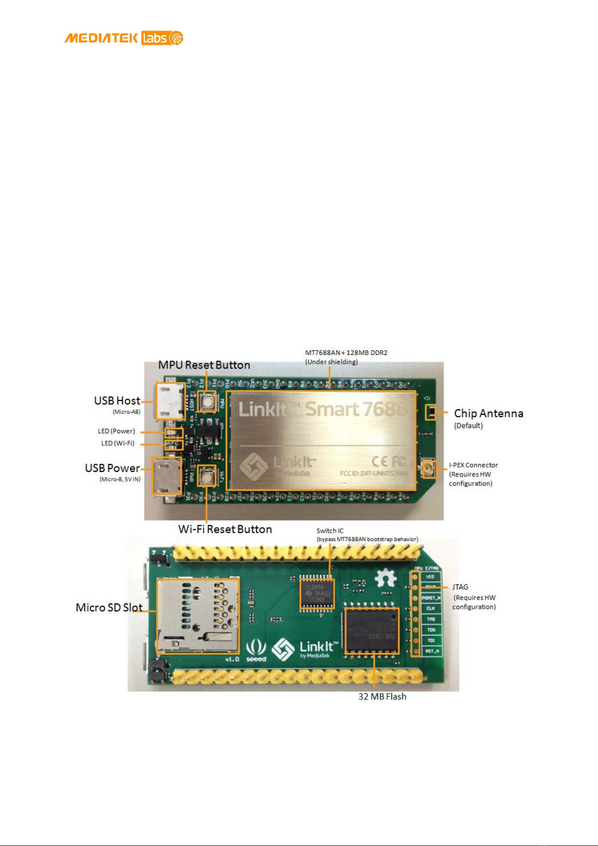
LinkIt Smart 7688 is shown in Figure 1.
Figure 1 LinkIt Smart 7688 development board (MPU only)
MediaTek LinkIt™ Smart 7688 Developer's Guide
© 2015, 2016 MediaTek Inc.
Page 12
This document contains information that is proprietary to MediaTek Inc.
Unauthorized reproduction or disclosure of this information in whole or in part is strictly prohibited.
2.2.2. Buttons
Description of how to use the buttons on the LinkIt Smart 7688 development board is provided in
Table 2.
Scenario
Button
Action
Reset the MPU MPU Reset Button
With the board
booted up, press the
button once
Reset Wi-Fi to AP
mode Wi-Fi Reset Button
With the board
booted up, press for
at least 5 seconds
and release
Factory reset and
enter AP mode.
WARNING: This
will restore the
board to default
setting and
remove all user
data
Wi-Fi Reset Button
With the board
booted up, press for
at least 20 seconds
and release
Upgrade firmware
from a USB drive Wi-Fi Reset Button
While the board is
powering up, press
the button for at
least 5 seconds and
release
Upgrade boot
loader from a USB
drive.
WARNING: This
will restore the
board to default
setting and
remove all user
data
Wi-Fi Reset Button
While the board is
powering up, press
the button for at
least 20 seconds and
release
Table 2 LinkIt Smart 7688 Development board buttons
2.2.3. LEDs
This section describes the functions of the LEDs available on the board.
•Power
The Power LED displays solid green when power is supplied to the board.
•Wi-Fi
The Wi-Fi LED is orange and displays the blink patterns described in Table 3.
Mode
Status
LED blink pattern
AP Mode With client device
3 blinks per second followed
by a pause for 0.5 seconds
(cycle repeats)
Without client Off
MediaTek LinkIt™ Smart 7688 Developer's Guide
© 2015, 2016 MediaTek Inc.
Page 13
This document contains information that is proprietary to MediaTek Inc.
Unauthorized reproduction or disclosure of this information in whole or in part is strictly prohibited.
Table 3 Wi-Fi LED blink pattern in LinkIt Smart 7688 HDK
For more information on Wi-Fi Access Point and Station modes, please see section 3.5, “Network
Environment”.
2.2.4. Antenna
There are two types of antenna supported on the LinkIt Smart 7688 development board:
1) Built in Wi-Fi chip antenna, this is the default antenna.
2) I-PEX connector for external antenna.
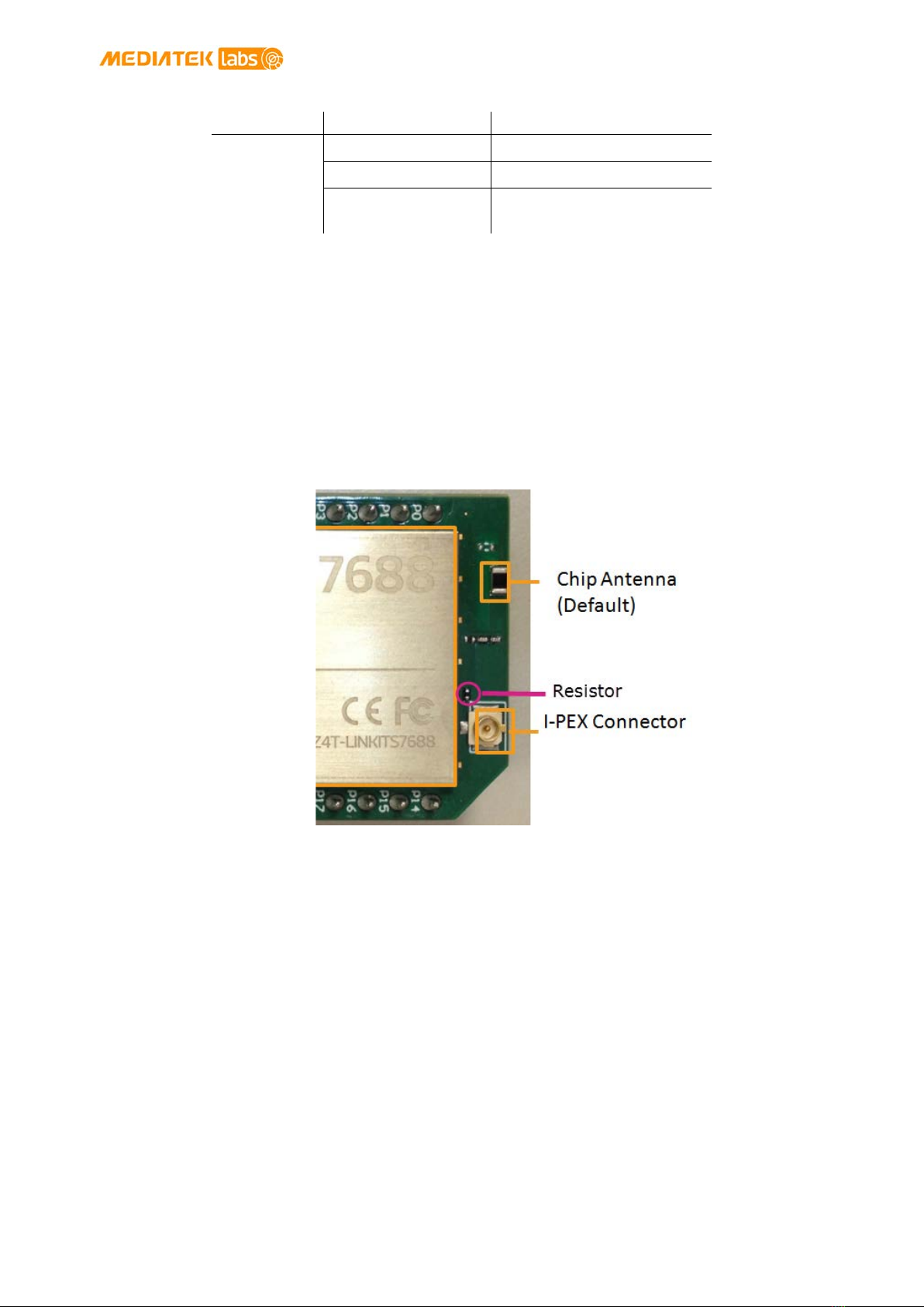
To enable the I-PEX connector, you’ll need to remove the resistor R233 located on the top
left corner of the I-PEX connector, as circled in Figure 4.
Figure 2 Removing resistor to enable I-PEX connector
2.2.5. USB Host
LinkIt Smart 7688 provides USB host capability that enables it to connect to various USB devices
such as webcams, USB drives, keyboards, joysticks and more. The connector is a USB micro-AB
type. Please see Figure 1 for the USB host connector location.
2.2.6. USB Power
A USB cable connected to a PC or other power source provides a 5V supply to the LinkIt Smart
7688 development board. When you add peripheral devices such as an SD card, USB drive or other
USB device to the development board, additional power may be consumed. Please use a high
quality USB cable to reduce power loss. If your peripheral device consumes power heavily, it’s
better to use an external power source for it.
The approximate power consumption of various devices used on the LinkIt Smart 7688 are
described in Table 4. Please see Figure 1 for the USB power connector location.
device
Station
Mode
Disconnected Off
Connecting 2 blinks per second
Connected Blinking based on the
transmitted data package

MediaTek LinkIt™ Smart 7688 Developer's Guide
© 2015, 2016 MediaTek Inc.
Page 14
This document contains information that is proprietary to MediaTek Inc.
Unauthorized reproduction or disclosure of this information in whole or in part is strictly prohibited.
Scenario
Approximate Power
Consumption
To establish Wi-Fi
connection
Peak 475.3 mA
Average 255.6 mA
Device boot up Peak 605.4 mA
Average 195.1 mA
Downloading a file to
an SD Card over Wi-Fi
Peak 540.4 mA
Average 275.8 mA
Downloading a file to
a USB Drive over Wi-Fi
Peak 569.5 mA
Average 304.9 mA
Downloading a file to
flash over Wi-Fi
Peak 522.4 mA
Average 271.3 mA
Table 4 Typical power consumption scenarios
Note: The suggested power source is 5V/1A.
2.2.7. Accessories
The standard LinkIt Smart 7688 sales package doesn’t includes accessories; you may therefore
require the following:
1) USB Power Cable (Required): You’ll need a USB type A to micro-B plug cable to power the
LinkIt Smart 7688 development board from a PC or other USB power source.
2) Micro USB OTG (On-The-Go) or Host Cable (Optional):An OTG cable, as shown in Figure
3, is used to connect Type A USB devices such as USB drives, USB cameras and more.
Figure 3 USB OTG cable
3) USB-UART Cable (Optional): This cable is used to enable communication to the Linux
console.
4) Micro SD Card (Optional): Use a micro SD card for extra storage space for application
code and data.
5) USB Drive (Optional): For extra storage. You can also use it to store boot loader and
firmware to upgrade the LinkIt Smart 7688.
MediaTek LinkIt™ Smart 7688 Developer's Guide
© 2015, 2016 MediaTek Inc.
Page 15
This document contains information that is proprietary to MediaTek Inc.
Unauthorized reproduction or disclosure of this information in whole or in part is strictly prohibited.
2.2.8. JTAG
You can use the JTAG interface to debug MT7688AN. To access the JTAG interface, you‘ll need to
unsolder resistor R95 and solder it to resistor R3 on the development board. After you’ve moved
the resistor and reboot the device you can activate the JTAG function. The hardware configuration
steps are:
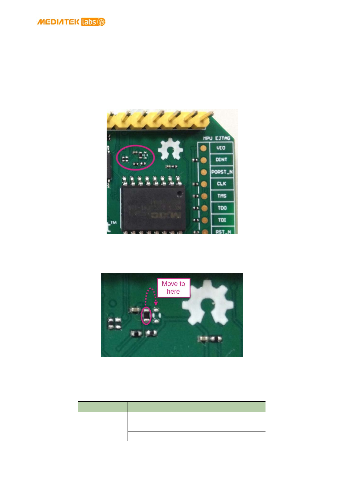
1) Find the group of resistors on the bottom of LinkIt Smart 7688 in the upper-right, as
circled in Figure 4.
Figure 4 JTAG resistors on the bottom of the LinkIt Smart 7688
2) Move a resistor by unsoldering and soldering it to a lower position as shown in Figure 5,
after you’ve finished moving the resistor, restart the device and you should be able to
activate the JTAG function.
Figure 5 Moving a resistor to access JTAG mode
2.2.9. Specifications
The key specifications of the LinkIt Smart 7688 development board are shown in Table 5.
Category
Feature
Specification
MPU Chipset MT7688AN
Core MIPS24KEc
Clock speed 580MHz

MediaTek LinkIt™ Smart 7688 Developer's Guide
© 2015, 2016 MediaTek Inc.
Page 16
This document contains information that is proprietary to MediaTek Inc.
Unauthorized reproduction or disclosure of this information in whole or in part is strictly prohibited.
Category
Feature
Specification
Working voltage 3.3V
PCB Size Dimensions 55.7 x 26 mm
Memory Flash 32MB
RAM 128MB DDR2
Power Source USB Power 5V (USB micro-B)
VCC 3.3V (Pin Breakout)
GPIO Pin Count 22 (MT7688AN)
Voltage 3.3v
PWM
Pin Count 4 (MT7688AN)
Voltage 3.3v
Max. Resolution 7 bits (customizable)
Maximum
Frequency@Resolution
100kHz@1-bit
50kHz@2-bit
25kHz@3-bit
12.5kHz@4-bit
6.25kHz@5-bit
3.125kHz@6-bit
1.5625kHz@7-bit
(Standard mode)
40MHz@1-bit
20MHz@2-bit
10MHz@3-bit
5MHz@4-bit
2.5MHz@5-bit
1.25Mhz@6-bit
625kHz@7-bit
(Fast mode)
External
Interrupts
Pin Count 22 (MT7688AN)
SPI
Set count 1 (MT7688AN)
Pin numbers
P22, P23,P24 (Shared
with on-board flash)
P25
Max. Speed 25 MHz
SPI Slave
Set count 1 (MT7688AN)
Pin numbers P28, P29, P30, P31
Max. Speed 25 MHz
I2S Set Count 1 (MT7688AN)
Pin numbers P10, P11, P12, P13
I2C
Set Count 1
Pin numbers P20, P21
Speed 120K/400K

MediaTek LinkIt™ Smart 7688 Developer's Guide
© 2015, 2016 MediaTek Inc.
Page 17
This document contains information that is proprietary to MediaTek Inc.
Unauthorized reproduction or disclosure of this information in whole or in part is strictly prohibited.
Category
Feature
Specification
UART Lite
Set Count 3 (MT7688AN)
Pin numbers P8, P9, P16, P17, P18,
P19
Max. Speed 0.5Mbps
USB Host
Set Count 1 (MT7688AN)
Pin numbers P6, P7
Connector type Micro-AB
Communication
Wi-Fi 1T1R 802.11 b/g/n (2.4G)
Ethernet 1-port 10/100 FE PHY
Pin numbers P2, P3, P4, P5
User Storage SD Card Micro SD
SDXC
Table 5 LinkIt Smart 7688 development boards specifications
2.2.10. Pin-out Diagram
This pin-out diagram helps you identify and map the pins on LinkIt Smart 7688 development
board to the peripheral devices you want to attach through interfaces such as GPIO, PWM, I2C, I2S,
SPI, UART and more. The available pins for the LinkIt Smart 7688 are illustrated in Figure 6. For
your convenience, this pin-out diagram can be downloaded from the MediaTek Labs website.

MediaTek LinkIt™ Smart 7688 Developer's Guide
© 2015, 2016 MediaTek Inc.
Page 18
This document contains information that is proprietary to MediaTek Inc.
Unauthorized reproduction or disclosure of this information in whole or in part is strictly prohibited.
Figure 6 LinkIt Smart 7688 Pin-out Diagram

MediaTek LinkIt™ Smart 7688 Developer's Guide
© 2015, 2016 MediaTek Inc.
Page 19
This document contains information that is proprietary to MediaTek Inc.
Unauthorized reproduction or disclosure of this information in whole or in part is strictly prohibited.
2.3. LinkIt Smart 7688 Duo
The LinkIt Smart 7688 Duo development board is powered by the same MT7688AN SOC as the
LinkIt Smart 7688, but includes an ATmega32U4 MCU. This supports additional features including
Analog I/O support and Arduino IDE support. The board’s functionality is therefore a combination
of that provided by the two chipsets: Wi-Fi and Ethernet are supported through OpenWrt Linux on
the MT7688AN SOC, and various peripheral supported through Arduino on the ATmega32U4
microcontroller.
2.3.1. Key Features
LinkIt Smart 7688 Duo’s key features include:
•1T1R Wi-Fi 802.11 b/g/n (2.4G).
•Pin-out for GPIO, I2C, I2S, SPI, SPIS, UART, PWM and Ethernet Port.
•580 MHz MIPS CPU.
•32MB flash and 128MB DDR2 RAM.
•USB host.
•Micro SD slot.
•Support for Arduino (ATmega32U4)
LinkIt Smart 7688 Duo is shown in Figure 7.
MediaTek LinkIt™ Smart 7688 Developer's Guide
© 2015, 2016 MediaTek Inc.
Page 20
This document contains information that is proprietary to MediaTek Inc.
Unauthorized reproduction or disclosure of this information in whole or in part is strictly prohibited.
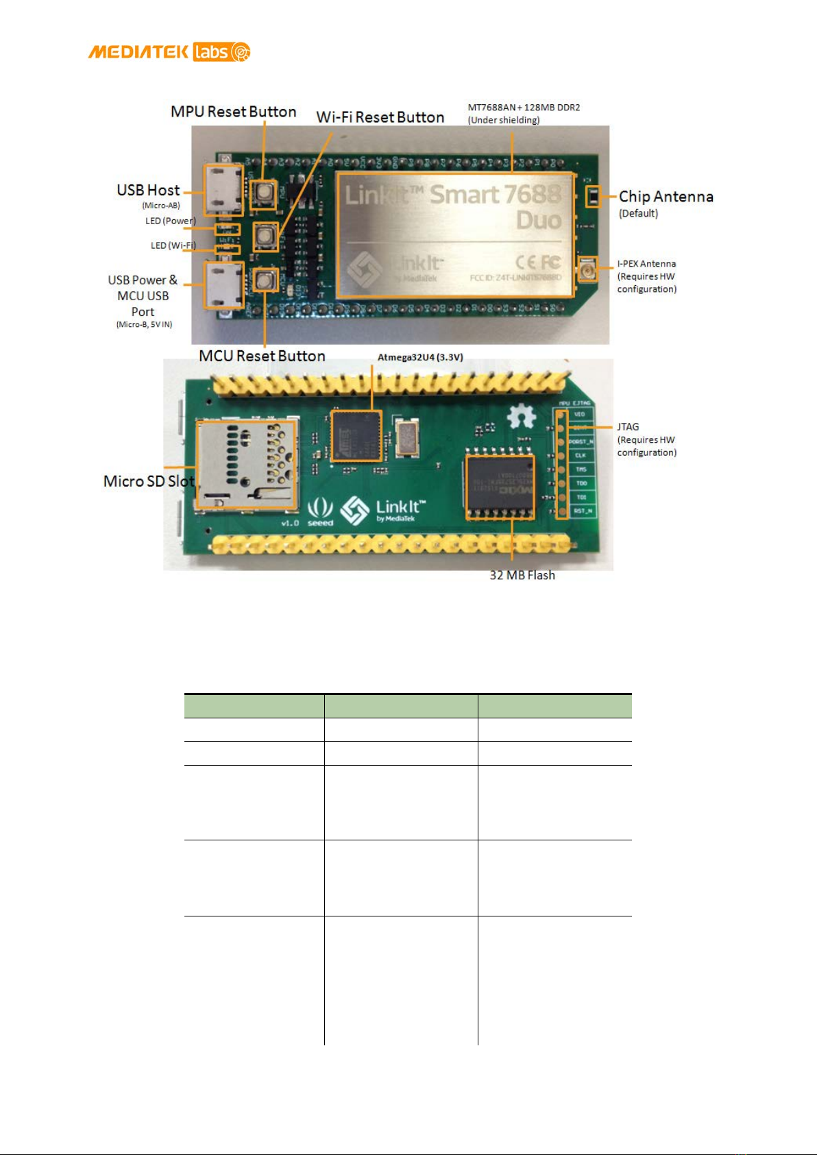
Figure 7 LinkIt Smart 7688 Duo development board (MPU + MCU)
2.3.2. Buttons
The buttons description on LinkIt Smart 7688 Duo and how to use them are described in Table 6.
Scenario
Button
Action
Resets the MPU MPU Reset Button
One press
Resets the MCU MCU Reset Button
One press
Enters MCU boot
loader mode
(Timeout after 8
seconds)
MCU Reset Button
Two presses within
750 milliseconds
Resets Wi-Fi to AP
mode
Wi-Fi Reset Button
After the board is
boot up, press the
button for at least 5
seconds and release
Factory resets and
enters AP mode
WARNING: Restore
to default setting
and all user data
will be removed
from the device
Wi-Fi Reset Button
After the board is
boot up, press the
button for at least 20
seconds and release
Other manuals for LinkIt Smart 7688
3
Table of contents
Other MEDIATEK Motherboard manuals

MEDIATEK
MEDIATEK Genio 1200 User manual

MEDIATEK
MEDIATEK LinkIt Smart 7688 Specification sheet

MEDIATEK
MEDIATEK Genio 700 Installation manual

MEDIATEK
MEDIATEK Genio 350 User manual

MEDIATEK
MEDIATEK Genio 350 Installation manual

MEDIATEK
MEDIATEK Genio 700 EVK User manual

MEDIATEK
MEDIATEK MT7612 User manual

MEDIATEK
MEDIATEK Genio 700 EVK User manual

MEDIATEK
MEDIATEK Genio 1200 User manual

MEDIATEK
MEDIATEK LinkIt 7697 HDK User manual


