A-Trend ATC-6510 User manual

1
CONTENTS
INDEX.......................................................................................... A
HOW TO USE THIS MANUAL……………………………….2
INTRODUCTION TO THE ATC-6510 MAINBOARD
HARDWARE……………………………………………………3
INSIDE THE ATC-6510 MAINBOARD PACKAGE………...4
CHAPTER 1 Introduction…………………………………..5
1-1 Soft-Off-Control..............................................................................5
1-2 LDCM ( LANDesk Client Manager, option) ............................... .6
1-3
Thermister (option)........................................................................ .7
1-4 Wake-On-LAN.............................................................................. .7
1-5 SB-Link Sideband Signals (JP3)…………………………………8
CHAPTER 2 Installation....................................................... 9
2-1 Installation Procedure ................................................................. .9
2-2 CPU Installation............................................................................ .10
2-3 System Memory Installation……………………………………..16
2-4 Connectors Description................................................................. .17
2-5 IDE Driver Installation ................................................................. .22
CHAPTER 3 Award BIOS Setup......................................... 23
3-1 Update BIOS Procedure................................................................ .24
3-1-1 Update Pentium II microcode API…………………………….25
3-2 Award System BIOS Configuration Setup................................... .26
Appendix A ……………………………………………………..56
Appendix B How to Install Pentium II CPU ? &
HowtoInstallCeleronCPU?
Appendix C How to Setup Thermister (option) ?
HOW TO USE THIS MANUAL

2
To obtain maximum use from this manual it is suggested:
Read Page A COMPONENT LOCATION DIAGRAM where you find the
mainboard layout diagram. Please refer to it when you configure the system.
Read about an overview of the mainboard features, packing contents, and how to
upgrade as well as to change hardware configurations such as memory size, CPU type,
jumper settings lists and connectors in the following categories:
INTRODUCTION TO THE ATC-6510 MAINBOARD HARDWARE
INSIDE THE ATC-6510 MAINBOARD PACKAGE
Chapter 1 Introduction
Chapter2 Installation
When you have finished reading of both chapter 1 and chapter 2, turn to Chapter 3
Award BIOS Setup where you will find the update BIOS procedure and the further
information which is stored in the SETUP is the system hardware configuration.
The back of this manual contains APPENDIX A which is a list of request form for
technical support, APPENDIX B which shows you how to setup Pentium II CPU and
APPENDIX C which shows you how to setup thermister.
Your system dealer will set up the mainboard according to your demand of the
computer. It means that the current settings of your mainboard may not be the same as
the defaults shown in this user's manual. If you need to change your configuration,
please ask your dealer first. Be sure this will not void your system warranty, or ask
your dealer to do it for you.
REMARK
Intel®is a registered trademark of Intel Corporation.
All other brands and product names are trademarks registered trademarks of their respective companies.
INTRODUCTION TO THE ATC-6510 MAINBOARD

3
HARDWARE
Each ATC-6510 mainboard supports or contains the following components:
! INTEL Pentium II CPU operating from 233MHz up to 333MHz.
! INTEL CeleronTM CPU operating from 266MHz up to 333MHz.
! INTEL 440EX PCIset.
! ATI AGP Rage IIC 3D VGA chipset.
! Yamaha 719/715 IIC 3D stereo sound PnP chipset, optional for ATI AGP Rage
Pro 3D.
! Using two 168-pin DIMM sockets, provides two banks of 64-bit wide path up to
256MB SDRAM or 256 EDO DRAM (with parity chip ECC support).
! Built-in Switching Voltage Regulator.(VRM 8.2 SPEC.)
! INTEL LDCM software.(option)
! Supports auto-detect CPU core voltage range 1.8V to 3.5V.
! Supports one AGP slot, three PCI slots with revision 2.1 interface compliant and
one 16-bit ISA slot.
! Dual Master IDE connectors support Ultra DMA/33, up to four devices in two
channels for connecting of high capacity hard drive, CD-ROM disk drive, tape
backup etc..
! Supports the USB (Universal Serial Bus) connector.
! PS/2 keyboard connector and PS/2 mouse connector.
! Winbond 83977 high-speed Ultra Multi-I/O chipset.
! Supports Infrared transfer (IrDA TX/RX) connection.
! One FDC port supports two devices up to 2.88MB.
! Two 16550A fast UARTs compatible serial ports.
! One EPP/ECP mode parallel printer port.
! Built-in Hardware Health Monitoring. (option)
! Built-in SGRAM optional for 2MB, 4MB, 8MB; default value is 4MB.
!
Hardware Dimension is 244mm x 244mm. (9.6" x 9.6")
INSIDE THE ATC-6510 MAINBOARD PACKAGE

4
The mainboard comes securely packed in a durable box and shipping carton. If any of
the following items are missing or damaged, please contact your supplier.
Each mainboard contains:
Q'TY
Description
1 Mainboard : ATC-6510.
1 Retentionmechanism(forPentiumIIinstallation)
1 CD(option) :LDCM,EnhancedIDEdriver
Award system BIOS Update Utility
1 Diskette(option) :EnhancedIDEdriver
Award system BIOS Update Utility
1 Cable :Thermistercable(option).
1 Cable :EnhancedIDEcable.
1 Cable :F.D.D.cable.
1 Manual :Usermanual.(Englishversion)
1 EnglishLDCMusermanual(option)
CHAPTER 1 INTRODUCTION

5
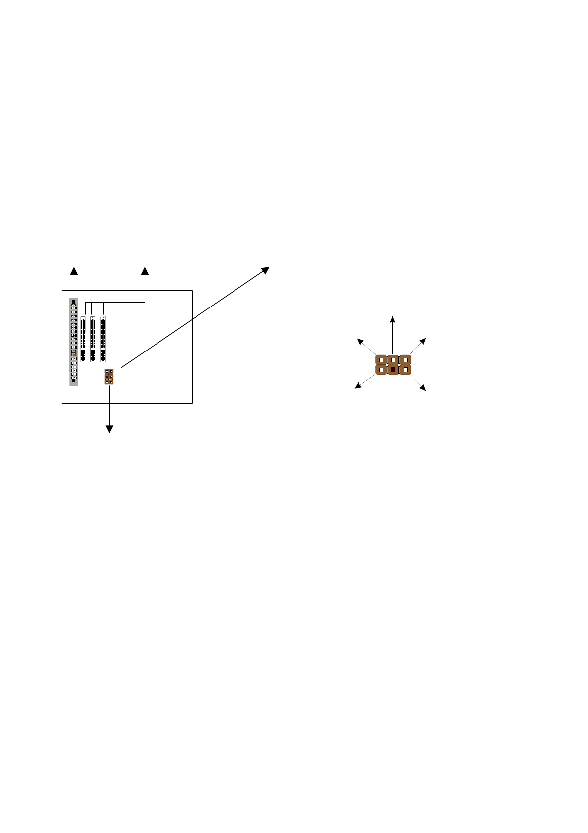
The ATC-6510 mainboard has ATI AGP Rage IIC 3D VGA chipset, Yamaha
719/715 IIC 3D stereo sound PnP chipsets and SGRAM (option) onboard. The ATI
AGP Rage IIC 3D VGA chipset using AGP interface technique which allows users
could have 3D display resolution without plug any of VGA cards and the Yamaha
719/715 IIC 3D stereo sound PnP chipset using ISA interface which could let your
system has 3D stereo sound. With 2MB SGRAM onboard, the mainboard can play
large volume games. If your mainboard built-in 4MB SGRAM, your system can
perform more powerful gamers e.g. 3D games. The 8 SGRAM onboard is to provide
users who need running volume CAD software.
1-1 SOFTWARE POWER OFF CONTROL
The mainboard design supports Software Power Off Control feature through the
SMM code in the BIOS under Windows 95, and MS-DOS operation system
environment. This is Intel ATX form factor feature and you should use ATX power
supply.
First, you should connect the power switch cable (provided by the ATX case
supplier) to the connector “PS-ON” on the mainboard. In the BIOS screen of
POWER MANAGEMENT SETUP’, choose “User Defined” (or “Min. Power Saving”
or “Max. Power Saving”) in ‘Power Manager’ and choose “Yes” in ‘PM Control by
APM’.
In Windows 95, if you would like to power off the system, you just choose
“shutdown the computer ?” in the “Shut Down Windows“ from Windows 95, then the
system power will be off directly, and become the stand-by status. You will find the
power LED light is not blinking (see the table below for the operating status). If
you would like to restart the system, just press the power switch button, and the
system will be powered on.
Note : If you will leave your system for several days, we suggest you use hardware
power off to shutdown your system.
Status Power LED Light Turbo LED Light
Software power off
control Light off Light off
APM mode Blinking Light on
System running Light on Light on
1-2 LDCM (
((
(LANDesk Client Manager)
))
)(option)

6
ATC-6510 built-in controller(option) support Intel LDCM. LDCM can satisfy
users who want manageable systems that can interact automatically with the user.
Client manager is the answer, enabling both administrators and clients to manage
systems. The features of LDCM are as following :
※View system inventory
Client Manager enables you to view hundreds of inventoried items. Some of these
items are software related, while many others are hardware related.
※View DMI-compliant component information
Client manager enables you to view component information that is compliant with the
Desktop Manager Interface(DMI). This means you can manage third-party DMI-
compliant components not included with Client manager.
※Back up and restore system configuration files.
Client Manager enables you back up and restore system configuration files. Whenever
you plan on changing the system configuration , you can make a backup set. If the
system no longer works correctly, after you change the system configuration , you
can simply restore the system configuration with the backup set.
※Troubleshoot
Since Client manager enables you to view the system inventory, you can easily
troubleshoot system problems.
※Receive notifications for system events
Client manager enables you to receive notification of certain system events. For
example, if the system is running low on virtual memory, you are notified of the
potential problem.
※Transfer files to and from client workstations
As an administrator, you have the ability to transfer files to and from client
workstation. This is helpful, for example, when you need to update a client
workstation driver.
※Remotely reboot client workstations
Administrator also have the ability to remotely reboot a workstation . This is helpful
when you want your system configuration settings to take effect.

7
1-3 Thermister (option)
This means that users can monitor the CPU temperature through thermister.
When setting up the thermister, the BIOS will load the CPU temperature automatically.
There is a choice of the warning beep sound if users set the option on. If the CPU
temperature overheated, users will get the notice from the thermister. This time you
should shut down computer and check your devices. Consequently, protecting and
monitoring the CPU temperature is the thermister’s job.
1-4 Wake-On-LAN
The remote Wake-On-LAN mode of operation is a mechanism that uses
Advanced Micro Device Magic Packet technology to power up a sleeping workstation
on the network. This mechanism is accomplished when the LAN card receives a
specific packet of information, called a Magic Packet, addressed to the node on the
network. For additional protection, Secure ON is an optional security feature that can
be added to the Magic Packet that requires a password to power up the sleeping
workstation. When the LAN card is in remote Wake-On-LAN mode, main system
power can be shut down leaving power only for the LAN card and auxiliary power
recondition.
The LAN card performs no network activities while in the remote
Wake-On-LAN mode of operation. It only monitors the network for receipt of a
Magic Packet. If a Magic Packet is addressed to the LAN card on the network, the
LAN card wake up the system. If the Secure ON feature has been enabled, the
password added to the Magic Packet is also verified prior to waking up the system.
WOL LAN card will provide a 3-pin line to connect the WOL connector on the
mainboard.
CAUTION :
For Wake-on-LAN, the +5V standby line for the power supply must capable of
Delievring +5V ±5% at 720mA. Failure to provide adequate standby current when
implementing Wake-on-LAN, can damage the power supply.
Before you enable Wake-on-LAN function, first check your power supply
specification to meet the above requirement or not.

8
1-5 SB-LINK Sideband Signals (JP3)
In order to migrate the legacy Sound Blaster compatible audio to the PCI bus,
EMU8008 incorporates a pair of SB-Link request/grant sideband signals (PCPCIR
EQ#A and PCPCISIRQ) to interface to the PCI bus. SB-Link is a mechanism that was
defined and developed by Creative as a docking solution which allows ISA slots to
exist in docking stations connected to desktop PC PCI bus.
ISA slot PCI slots JP32x3 sideband header, sound will also
has a 2x3 header and a cable.
JP3
GND REQ#A GND
GNT#A SIRQ

9
CHAPTER 2 INSTALLATION
2-1 INSTALLATION PROCEDURE
Before installing the computer, please prepare all components such as CPU, DRAM;
peripherals such as hard drive, keyboard, CD-ROM disk drive and accessories such as
cables. Then, install the system as following:
1. Plug CPU/ heat sink (refer to Pentium II installation guide, Appendix A), and
DRAM modules on the mainboard.
2. Set DIP switch based on your configuration.
3. Plug add-on cards into PCI/ISA slots, if needed.
4. Connect cables to peripherals, specially for VGA and Sound connector.
5. Make sure all components and devices are well connected, turn on the power and
setup System BIOS based on your configuration.
6. Install peripherals, add-on card drivers and test them.
7. If all of above procedures are success, turn-off the power then plug all of them into
your computer case.
Remark :
Before you do the mainboard installation, please keep in mind that VGA
and Sound chipsets are built-in on the ATC-6510 mainboard along with
MicroATX Form Factor.

10
2-2 CPU INSTALLATION
The 6510 mainboard supports both INTEL Pentium II CPU and Celeron CPU.
2-2-1 CPU TYPE SELECTION (by BIOS)
1.Press the <Del> key when the system is booting up.
2.The following main menu will appear.
ROM PCI/ISA BIOS (ATC-6510)
CMOS SETUP UTILITY
AWARD SOFTWARE, INC.
STANDARD CMOS SETUP INTEGRATED PERIPHERALS
BIOS FEATURES SETUP SUPERVISOR PASSWORD
CHIPSET FEATURES SETUP USER PASSWORD
POWER MANAGEMENT SETUP IDE HDD AUTO DETECTION
PNP/PCI CONFIGURATION SAVE & EXIT SETUP
LOAD BIOS DEFAULTS EXIT WITHOUT SAVING
LOAD SETUP DEFAULTS
ESC: Quit #$%&:Select Item
F10: Save & Exit Setup (Shift) F2 : Change Color
AT Clock, DRAM Timings, .......
3. Select “ CHIPSET FEATURES SETUP ”
STANDARD CMOS SETUP INTEGRATED PERIPHERALS
BIOS FEATURES SETUP SUPERVISOR PASSWORD
CHIPSET FEATURES SETUP USER PASSWORD
POWER MANAGEMENT SETUP IDE HDD AUTO DETECTION
PNP/PCI CONFIGURATION SAVE & EXIT SETUP
LOAD BIOS DEFAULTS EXIT WITHOUT SAVING
LOAD SETUP DEFAULTS
ESC: Quit #$%&:Select Item
F10: Save & Exit Setup (Shift) F2 : Change Color
AT Clock, DRAM Timings, .......

11
4. Then the following screen will appear.
ROM PCI/ISA BIOS (ATC-6510)
CHIPSET FEATURES SETUP
AWARD SOFTWARE, INC.
Auto Configuration : Enabled SDRAM CAS latency Time : 3
DRAM Speed Selection : 60 ns CPU Clock Ratio : 2.0x
MA Wait State : Slow Auto Detect DIMM/PCI ClK : Enabled
EDO RAS# To CAS# Delay : 3 CPU Clock Frequency : 66MHz
EDO RAS# Precharge Time : 3 Spread Spectrum Modulated : Disabled
EDO DRAM Read Burst : x333 *Following menus are optional*
EDO DRAM Write Burst : x222 *CPU Warning Temperature : Disabled
CPU-To-PCI IDE Posting : Disabled *Current System Temperature : 20 o C/ 68 o F
System BIOS Cacheable : Disabled *Current CPU Temperature : 20 o C/ 68 o F
Video BIOS Cacheable : Disabled *Current ChassisFAN Speed : 0 PRM
Video RAM Cacheable : Disabled *Current PWRFAN Speed : 0 PRM
8 Bit I/O Recovery Time : 3 *Current CPUFAN Speed : 0 RPM
16 Bit I/O Recovery Time : 2 *Vcore : 2.80V VTT(V) : 1.47V
Memory Hole At 15M-16M : Disabled *+3.3V : 3.45V +5V : 4.91V
Passive Release : Enabled *+12V : 12.22V –12V : -11.76
Delayed Transaction : Disabled *-5V : -5.16V
AGP Aperture Size (MB) : 128 Esc: Quit #$%&:Select Item
SDRAM RAS-to-CAS Delay : Slow F1 : Help PU/PD/+/-:Modify
SDRAM RAS Precharge Time : Slow F5 : Old Values (Shift)F2 :Color
F6 :Load BIOS Defaults
F7 :Load Setup Defaults
※※ NOTE
If an incorrect CPU frequency is set through the BIOS, a system failure may
occur. This system failure can be solved by pressing the “Insert” key on the
keyboard to clear up the previous set frequency (i.e. back to 133MHz (66MHz x 2.0)
or the default frequency), and then the power button to restart the system and reset
the value in BIOS screen. Or user can clear CMOS to reset the BIOS value.
Also the ATC-6510 mainboard supports keyboard power on or
mouse power on function, (refer to ‘Integrated Peripherals’, page48,49).
When you set ‘keyboard power on’, you can select set password or not.
When you set password, you should key-in the password to power on
the system. If you forget the password, you should clear CMOS to reset
the system.

12
5a. Intel Pentium II 233MHz (66 x 3.5)
ROM PCI/ISA BIOS (ATC-6510)
CHIPSET FEATURES SETUP
AWARD SOFTWARE, INC.
Auto Configuration : Enabled SDRAM CAS latency Time : 3
DRAM Speed Selection : 60 ns CPU Clock Ratio : 3.5x
MA Wait State : Slow Auto Detect DIMM/PCI ClK : Enabled
EDO RAS# To CAS# Delay : 3 CPU Clock Frequency : 66MHz
EDO RAS# Precharge Time : 3 Spread Spectrum Modulated : Disabled
EDO DRAM Read Burst : x333 *Following menus are optional*
EDO DRAM Write Burst : x222 *CPU Warning Temperature : Disabled
CPU-To-PCI IDE Posting : Disabled *Current System Temperature : 20 o C/ 68 o F
System BIOS Cacheable : Disabled *Current CPU Temperature : 20 o C/ 68 o F
Video BIOS Cacheable : Disabled *Current ChassisFAN Speed : 0 PRM
Video RAM Cacheable : Disabled *Current PWRFAN Speed : 0 PRM
8 Bit I/O Recovery Time : 3 *Current CPUFAN Speed : 0 RPM
16 Bit I/O Recovery Time : 2 *Vcore : 2.80V VTT(V) : 1.47V
Memory Hole At 15M-16M : Disabled *+3.3V : 3.45V +5V : 4.91V
Passive Release : Enabled *+12V : 12.22V –12V : -11.76
Delayed Transaction : Disabled *-5V : -5.16V
AGP Aperture Size (MB) : 128 Esc: Quit #$%&:Select Item
SDRAM RAS-to-CAS Delay : Slow F1 : Help PU/PD/+/-:Modify
SDRAM RAS Precharge Time : Slow F5 : Old Values (Shift)F2 :Color
F6 :Load BIOS Defaults
F7 :Load Setup Defaults

13
5b. Intel Pentium II 266MHz (66 x 4.0)
ROM PCI/ISA BIOS (ATC-6510)
CHIPSET FEATURES SETUP
AWARD SOFTWARE, INC.
Auto Configuration : Enabled SDRAM CAS latency Time : 3
DRAM Speed Selection : 60 ns CPU Clock Ratio : 4.0x
MA Wait State : Slow Auto Detect DIMM/PCI ClK : Enabled
EDO RAS# To CAS# Delay : 3 CPU Clock Frequency : 66MHz
EDO RAS# Precharge Time : 3 Spread Spectrum Modulated : Disabled
EDO DRAM Read Burst : x333 *Following menus are optional*
EDO DRAM Write Burst : x222 *CPU Warning Temperature : Disabled
CPU-To-PCI IDE Posting : Disabled *Current System Temperature : 20 o C/ 68 o F
System BIOS Cacheable : Disabled *Current CPU Temperature : 20 o C/ 68 o F
Video BIOS Cacheable : Disabled *Current ChassisFAN Speed : 0 PRM
Video RAM Cacheable : Disabled *Current PWRFAN Speed : 0 PRM
8 Bit I/O Recovery Time : 3 *Current CPUFAN Speed : 0 RPM
16 Bit I/O Recovery Time : 2 *Vcore : 2.80V VTT(V) : 1.47V
Memory Hole At 15M-16M : Disabled *+3.3V : 3.45V +5V : 4.91V
Passive Release : Enabled *+12V : 12.22V –12V : -11.76
Delayed Transaction : Disabled *-5V : -5.16V
AGP Aperture Size (MB) : 128 Esc: Quit #$%&:Select Item
SDRAM RAS-to-CAS Delay : Slow F1 : Help PU/PD/+/-:Modify
SDRAM RAS Precharge Time : Slow F5 : Old Values (Shift)F2 :Color
F6 :Load BIOS Defaults
F7 :Load Setup Defaults

14
5c. Intel Pentium II 300MHz (66 x 4.5)
ROM PCI/ISA BIOS (ATC-6510)
CHIPSET FEATURES SETUP
AWARD SOFTWARE, INC.
Auto Configuration : Enabled SDRAM CAS latency Time : 3
DRAM Speed Selection : 60 ns CPU Clock Ratio : 4.5x
MA Wait State : Slow Auto Detect DIMM/PCI ClK : Enabled
EDO RAS# To CAS# Delay : 3 CPU Clock Frequency : 66MHz
EDO RAS# Precharge Time : 3 Spread Spectrum Modulated : Disabled
EDO DRAM Read Burst : x333 *Following menus are optional*
EDO DRAM Write Burst : x222 *CPU Warning Temperature : Disabled
CPU-To-PCI IDE Posting : Disabled *Current System Temperature : 20 o C/ 68 o F
System BIOS Cacheable : Disabled *Current CPU Temperature : 20 o C/ 68 o F
Video BIOS Cacheable : Disabled *Current ChassisFAN Speed : 0 PRM
Video RAM Cacheable : Disabled *Current PWRFAN Speed : 0 PRM
8 Bit I/O Recovery Time : 3 *Current CPUFAN Speed : 0 RPM
16 Bit I/O Recovery Time : 2 *Vcore : 2.80V VTT(V) : 1.47V
Memory Hole At 15M-16M : Disabled *+3.3V : 3.45V +5V : 4.91V
Passive Release : Enabled *+12V : 12.22V –12V : -11.76
Delayed Transaction : Disabled *-5V : -5.16V
AGP Aperture Size (MB) : 128 Esc: Quit #$%&:Select Item
SDRAM RAS-to-CAS Delay : Slow F1 : Help PU/PD/+/-:Modify
SDRAM RAS Precharge Time : Slow F5 : Old Values (Shift)F2 :Color
F6 :Load BIOS Defaults
F7 :Load Setup Defaults

15
5d. Intel Pentium II 333MHz (66 x 5.0)
ROM PCI/ISA BIOS (ATC-6510)
CHIPSET FEATURES SETUP
AWARD SOFTWARE, INC.
Auto Configuration : Enabled SDRAM CAS latency Time : 3
DRAM Speed Selection : 60 ns CPU Clock Ratio : 5.0x
MA Wait State : Slow Auto Detect DIMM/PCI ClK : Enabled
EDO RAS# To CAS# Delay : 3 CPU Clock Frequency : 66MHz
EDO RAS# Precharge Time : 3 Spread Spectrum Modulated : Disabled
EDO DRAM Read Burst : x333 *Following menus are optional*
EDO DRAM Write Burst : x222 *CPU Warning Temperature : Disabled
CPU-To-PCI IDE Posting : Disabled *Current System Temperature : 20 o C/ 68 o F
System BIOS Cacheable : Disabled *Current CPU Temperature : 20 o C/ 68 o F
Video BIOS Cacheable : Disabled *Current ChassisFAN Speed : 0 PRM
Video RAM Cacheable : Disabled *Current PWRFAN Speed : 0 PRM
8 Bit I/O Recovery Time : 3 *Current CPUFAN Speed : 0 RPM
16 Bit I/O Recovery Time : 2 *Vcore : 2.80V VTT(V) : 1.47V
Memory Hole At 15M-16M : Disabled *+3.3V : 3.45V +5V : 4.91V
Passive Release : Enabled *+12V : 12.22V –12V : -11.76
Delayed Transaction : Disabled *-5V : -5.16V
AGP Aperture Size (MB) : 128 Esc: Quit #$%&:Select Item
SDRAM RAS-to-CAS Delay : Slow F1 : Help PU/PD/+/-:Modify
SDRAM RAS Precharge Time : Slow F5 : Old Values (Shift)F2 :Color
F6 :Load BIOS Defaults
F7 :Load Setup Defaults

16
5e. Intel CeleronTM CPU 266MHz (66 x 4.0)
ROM PCI/ISA BIOS (ATC-6510)
CHIPSET FEATURES SETUP
AWARD SOFTWARE, INC.
Auto Configuration : Enabled SDRAM CAS latency Time : 3
DRAM Speed Selection : 60 ns CPU Clock Ratio : 4.0x
MA Wait State : Slow Auto Detect DIMM/PCI ClK : Enabled
EDO RAS# To CAS# Delay : 3 CPU Clock Frequency : 66MHz
EDO RAS# Precharge Time : 3 Spread Spectrum Modulated : Disabled
EDO DRAM Read Burst : x333 *Following menus are optional*
EDO DRAM Write Burst : x222 *CPU Warning Temperature : Disabled
CPU-To-PCI IDE Posting : Disabled *Current System Temperature : 20 o C/ 68 o F
System BIOS Cacheable : Disabled *Current CPU Temperature : 20 o C/ 68 o F
Video BIOS Cacheable : Disabled *Current ChassisFAN Speed : 0 PRM
Video RAM Cacheable : Disabled *Current PWRFAN Speed : 0 PRM
8 Bit I/O Recovery Time : 3 *Current CPUFAN Speed : 0 RPM
16 Bit I/O Recovery Time : 2 *Vcore : 2.80V VTT(V) : 1.47V
Memory Hole At 15M-16M : Disabled *+3.3V : 3.45V +5V : 4.91V
Passive Release : Enabled *+12V : 12.22V –12V : -11.76
Delayed Transaction : Disabled *-5V : -5.16V
AGP Aperture Size (MB) : 128 Esc: Quit #$%&:Select Item
SDRAM RAS-to-CAS Delay : Slow F1 : Help PU/PD/+/-:Modify
SDRAM RAS Precharge Time : Slow F5 : Old Values (Shift)F2 :Color
F6 :Load BIOS Defaults
F7 :Load Setup Defaults

17
5f. Intel CeleronTM CPU 300MHz (66 x 4.5)
ROM PCI/ISA BIOS (ATC-6510)
CHIPSET FEATURES SETUP
AWARD SOFTWARE, INC.
Auto Configuration : Enabled SDRAM CAS latency Time : 3
DRAM Speed Selection : 60 ns CPU Clock Ratio : 4.5x
MA Wait State : Slow Auto Detect DIMM/PCI ClK : Enabled
EDO RAS# To CAS# Delay : 3 CPU Clock Frequency : 66MHz
EDO RAS# Precharge Time : 3 Spread Spectrum Modulated : Disabled
EDO DRAM Read Burst : x333 *Following menus are optional*
EDO DRAM Write Burst : x222 *CPU Warning Temperature : Disabled
CPU-To-PCI IDE Posting : Disabled *Current System Temperature : 20 o C/ 68 o F
System BIOS Cacheable : Disabled *Current CPU Temperature : 20 o C/ 68 o F
Video BIOS Cacheable : Disabled *Current ChassisFAN Speed : 0 PRM
Video RAM Cacheable : Disabled *Current PWRFAN Speed : 0 PRM
8 Bit I/O Recovery Time : 3 *Current CPUFAN Speed : 0 RPM
16 Bit I/O Recovery Time : 2 *Vcore : 2.80V VTT(V) : 1.47V
Memory Hole At 15M-16M : Disabled *+3.3V : 3.45V +5V : 4.91V
Passive Release : Enabled *+12V : 12.22V –12V : -11.76
Delayed Transaction : Disabled *-5V : -5.16V
AGP Aperture Size (MB) : 128 Esc: Quit #$%&:Select Item
SDRAM RAS-to-CAS Delay : Slow F1 : Help PU/PD/+/-:Modify
SDRAM RAS Precharge Time : Slow F5 : Old Values (Shift)F2 :Color
F6 :Load BIOS Defaults
F7 :Load Setup Defaults

18
5g. Intel CeleronTM CPU 333MHz (66 x 5.0)
ROM PCI/ISA BIOS (ATC-6510)
CHIPSET FEATURES SETUP
AWARD SOFTWARE, INC.
Auto Configuration : Enabled SDRAM CAS latency Time : 3
DRAM Speed Selection : 60 ns CPU Clock Ratio : 5.0x
MA Wait State : Slow Auto Detect DIMM/PCI ClK : Enabled
EDO RAS# To CAS# Delay : 3 CPU Clock Frequency : 66MHz
EDO RAS# Precharge Time : 3 Spread Spectrum Modulated : Disabled
EDO DRAM Read Burst : x333 *Following menus are optional*
EDO DRAM Write Burst : x222 *CPU Warning Temperature : Disabled
CPU-To-PCI IDE Posting : Disabled *Current System Temperature : 20 o C/ 68 o F
System BIOS Cacheable : Disabled *Current CPU Temperature : 20 o C/ 68 o F
Video BIOS Cacheable : Disabled *Current ChassisFAN Speed : 0 PRM
Video RAM Cacheable : Disabled *Current PWRFAN Speed : 0 PRM
8 Bit I/O Recovery Time : 3 *Current CPUFAN Speed : 0 RPM
16 Bit I/O Recovery Time : 2 *Vcore : 2.80V VTT(V) : 1.47V
Memory Hole At 15M-16M : Disabled *+3.3V : 3.45V +5V : 4.91V
Passive Release : Enabled *+12V : 12.22V –12V : -11.76
Delayed Transaction : Disabled *-5V : -5.16V
AGP Aperture Size (MB) : 128 Esc: Quit #$%&:Select Item
SDRAM RAS-to-CAS Delay : Slow F1 : Help PU/PD/+/-:Modify
SDRAM RAS Precharge Time : Slow F5 : Old Values (Shift)F2 :Color
F6 :Load BIOS Defaults
F7 :Load Setup Defaults

19
2-3 SYSTEM MEMORY INSTALLATION
The ATC-6510 provides two 168-pin DIMM sockets for system memory
expansion from 8MB to 256MB. These two DIMMs are arranged to two banks,
please refer to page A. Each bank provides 64-bit wide data path.
※
※※
※Samples of System Memory Combinations Options ※
※※
※
BANK0 BANK1 Total Memory
DIMM 1 DIMM 2 DIMM 1-2
8MBx1 - 8MB
- 8MBx1 8MB
8MBx1 8MBx1 16MB
16MBx1 - 16MB
- 16MBx1 16MB
8MBx1 16MBx1 24MB
16MBx1 8MBx1 24MB
16MBx1 16MBx1 32MB
32MBx1 - 32MB
- 32MBx1 32MB
32MBx1 32MBx1 64MB
32MBx1 64MBx1 96MB
64MBx1 32MBx1 96MB
64MBx1 64MBx1 128MB
: : :
128MBx1 128MBx1 256MB

20
2-4 CONNECTORS DESCRIPTION
The locations of following connectors are indicated in page A. When you plug
wires into the following connector of CONN1, you should have the pin 1 edge of the
wires align with the pin 1 end of the connector.
CONN1 : speaker, keyboard lock, reset, SMI,
turbo LED, and IDE LED connectors.
Slot1
TB-LED : Turbo LED indicator, LED on
whensystemrunshigherspeed.
GND
+5V
SPK KEYLOCK
RST EXTSMI TB-LED IDE-LED
SPK : speaker
Speaker
GND
GND
VCC
Power LED connector
Power LED +
N/C
GND (power)
Keylock
GND
RST : Reset connector
ResetSignal
GND
SMI : SMI lead
GND
SMI Signal
PS ON
Table of contents
Other A-Trend Motherboard manuals

A-Trend
A-Trend ATC-6230 User manual

A-Trend
A-Trend ATC-6260 User manual

A-Trend
A-Trend ATC5200M User manual

A-Trend
A-Trend ATC6240V User manual

A-Trend
A-Trend Atc-6240m Mounting instructions

A-Trend
A-Trend ATC-6120 User manual

A-Trend
A-Trend ATC-6130E User manual

A-Trend
A-Trend ATC-5030 User manual

A-Trend
A-Trend 6220M User manual

A-Trend
A-Trend 6241 User manual