Medifa MAT 504220 User manual

Service Manual
Technical Documentation
MAT 504220/ 504225
Operation Table
504220 504225
English
Index
I. Safety Instructions ...................................
II. Normal Use ..............................................
III. Exposing and Removing of the Column
Cover and Control Panel ...........................
IV. Exchange of the Upholstery.....................
V. Replacement of the Motor for the Trend-
elenburg Adjustment as well as the Pull
Spring for Stabilization .............................
VI. Gas Springs for Back Rest Adjustment....
- Dismantling of the Gas Springs .......
- Montage of the New Gas Springs ...
- Replacement of the Release
Handle/Button ..................................
VII. Dismantling of the Upper Frame ..............
- Model 504220 ..................................
- Model 504225 ..................................
VIII. Replacement of the Distribution Panel.....
2
3
4-7
8-9
10-12
13-16
13-14
15
16
17-19
17
18-19
20
IX. Replacement of the Limit Switches (only
504225)..........................................................
X. Dismantling of the Joint Frame incl. Motor for
Lateral Tilt ......................................................
XI. Dismantling of the Lift Column.......................
XII. Dismantling of the Control Panel ...................
XIII. Dismantling of the Movability Function .........
XIV. Dismantling of the Shifting (only 504225)......
XV. Dismantling of the Accumulators...................
XVI. Wiring Diagram..............................................
XVII. Lists of Spare Parts/Drawings .......................
- OP-Table MAT 504220/25 ....................
- Head Plate Art.-No. 61144 ....................
- Small Head Plate Art.-No. 61143..........
- Devided Leg Plate Art.-No. 61615 ........
XVIII. Service and Maintenance Schedule ..............
XIX. Diagnosis (Remote Diagnosis) ......................
21
22-23
24-25
26
27-29
30-31
32
33
34-39
34-35
36
37
38-39
40-44
45-50
Service Manual - MAT 504220/ 504225 Operation Table
The operation table has been manufactured according to the state of the art as well as to the valid safety
specifications and requirements.
Nevertheless, improper handling and/or damages on the operating table can lead to safety hazards for the
user and/or other persons and tangible assets.
Only start running the operating table when in perfect condition. This table has been solely designed for normal
use. Operators should keep in mind to handle the table in compliance with the safety rules and recommendati-
ons as listed in this manual, in order to avoid any hazards which may occur from improper handling. Any de-
faults which may affect the safety have to be repaired immediately!
The table comes with conductive double castors, conductive upholstery and an equipotential bonding.The ope-
ration table can be used in a Zone M - given the area is equipped with a conductive floor.
Always keep this manual close at hand. Please notice as well all legal and further guidelines and regulations
for accident prevention and pollution control.
Do not replace, change or repair any devices of the above mentioned table without the authorization of the ma-
nufacturer. All repairs and maintenance services need to be carried out by the manufacturer or by authorized
personnel.
Spare parts need to be in accordance with the requirements of the manufacturer. Original spare parts always
guarantee the proper running of the operation table.
Keep the mandatory deadlines for recurring controls as stated in this service manual!
Think of an environement friendly disposal of equipment and faulty parts!
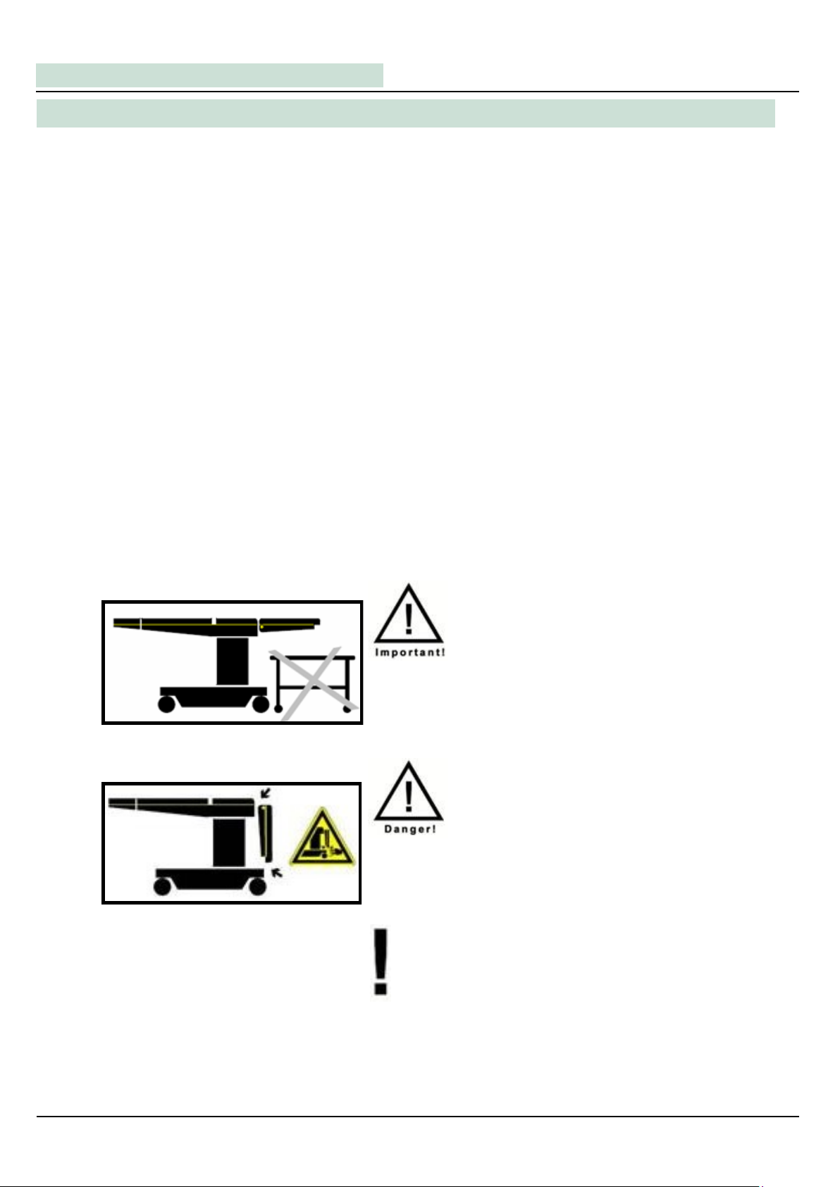
Think of a barrier free surrounding before carrying out a
downward or tilting motion!
DANGER OF TILTING!
Do not touch below or between any surface components or
parts.
DANGER OF SQUEEZING!
Avoid collisions between parts of the table top and the co-
lumn, when carrying out the following adjustments:
Height adjustment (downwards)
Tilt adjustment
Legplate Adjustment (downwards)
I. Safety Instructions
2

In compliance with the fullfilled regulations and rules of the international standard IEC 60601-1 and
IEC 60601-2-46 this table is a Class I device, following the classification of the law for medical products
(Medizinproduktegesetz)(MPG).
It has to be listed in a respective index. All maintenance works, new installations, adjustments and mountings
should be reported in that index.
Alway keep in mind, that all of the above mentioned works should be solely carried out by Medifa Service
Technicians to guarantee a long, safe and proper function of the product.
This is an important requirement for all kind of warranty claims!
Operation tables, manufactured by Medifa, have been exclusively designed for human medicine and
should only be operated by authorized personnel in areas equipped according to the known standards.
Authorized personnel by definition are persons who took part in a training for the correct use of the device
by specially skilled staff.
This training will be documented and confirmed in a respective report.
Only use tables in a perfect condition and maintenanced according to the given schedule!
II. Normal Use
medifa
®
medifa-hesse GmbH & Co. KG –Industriestraße 5 –D-57413 Finnentrop, Tel.: +49 (0) 2721-7177-0 –Fax: +49 (0) 2721-7177-77 3
Attention:
This manual is based on the knowledge and contents of a training for skilled staff.
This manuel cannot replace the absolutely necessary training for the operation and
maintenance of our products!
Service Manual - MAT 504220/ 504225 Operation Table
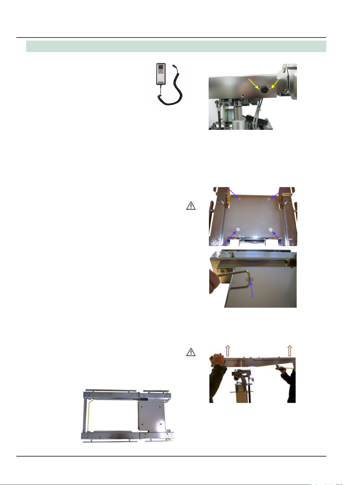
For various repairs the column cover needs to be removed.
Do as follows:
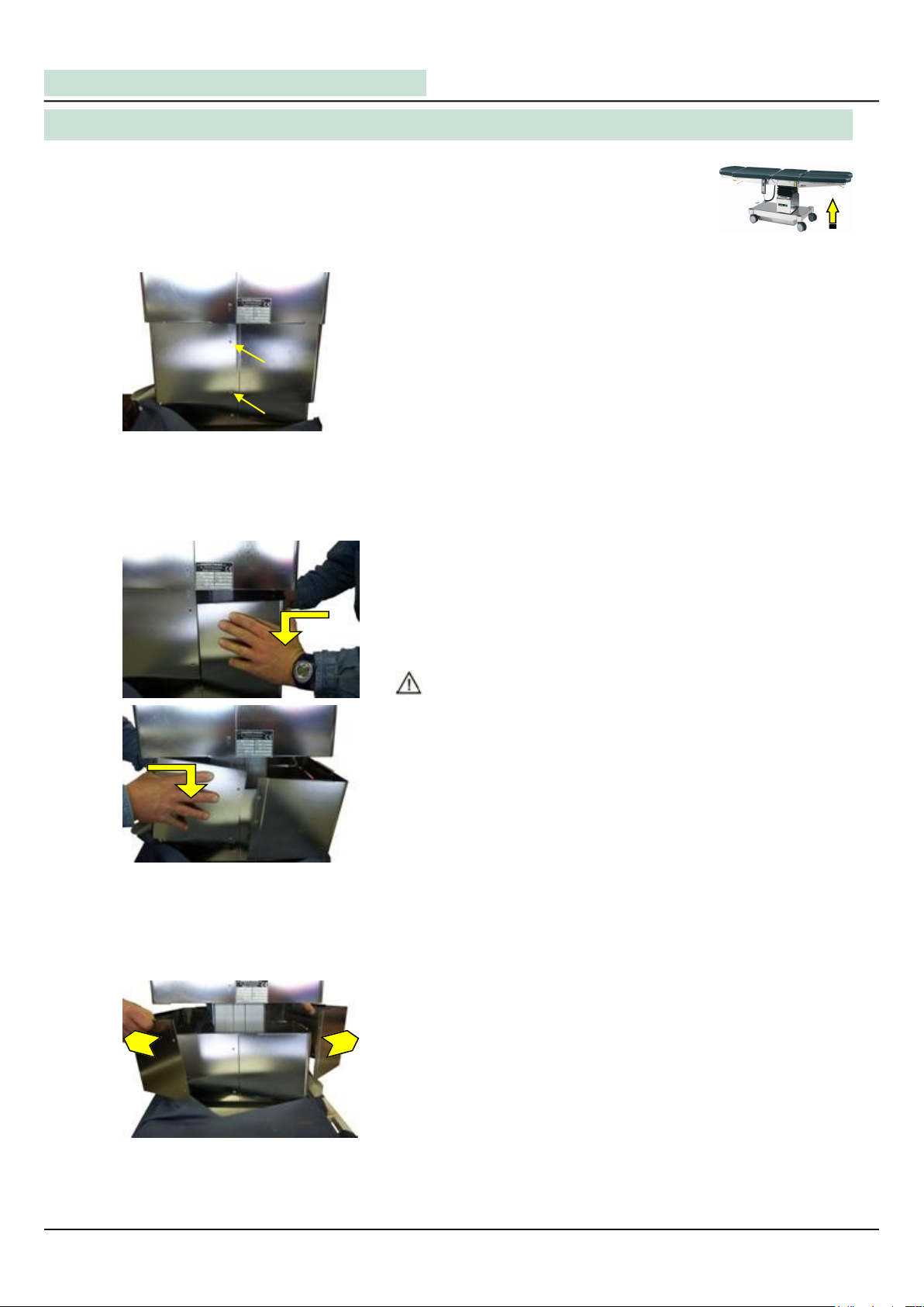
Use the hand switch or the control panel and put the table into the top position.
Remove the supply cable, if necessary. Turn off the table at the base.
III. Exposing and Removing of the Column Cover and Control Panel
4
Loosen the screws on the back of the middle part of the
cover.
When unhooked, the cover can be bend up around the lower
cover and can be dismantled.
fig. 1: open the middle part of the column
fig. 4: dismantle middle part of the co-
lumn
fig. 2+3: unhook the middle part of the
column
After removing both screws, the cover can be unhooked from
the upper cover by pushing it to the inside and pulling it down
at the same time. Repeat this procedure on the other side
and you will be able to completely uncover the middle part.
Attention:
Be careful to prevent the cover from falling down!
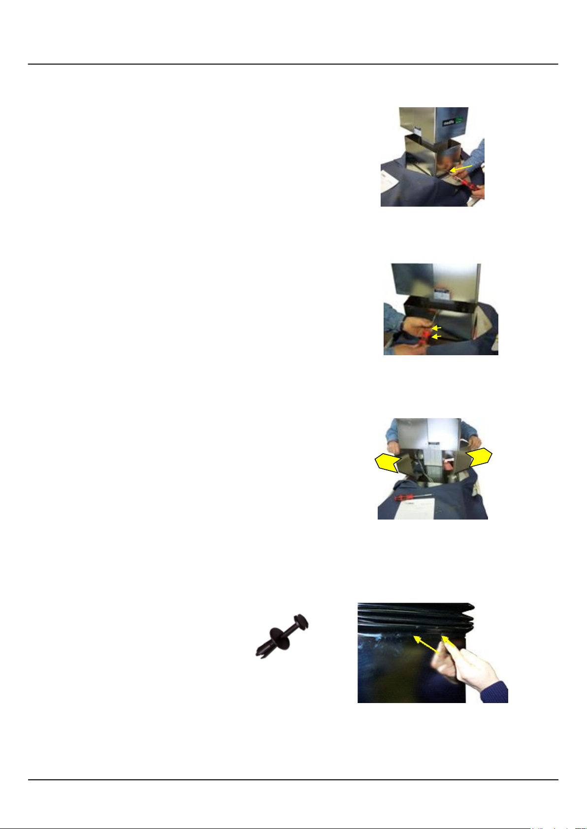
Remove the screws on the left and on the right to dismantle
the lower cover.
fig. 5: dismantle the lower cover
medifa
®
medifa-hesse GmbH & Co. KG –Industriestraße 5 –D-57413 Finnentrop, Tel.: +49 (0) 2721-7177-0 –Fax: +49 (0) 2721-7177-77 5
fig. 6: dismantle the lower cover
Now, loosen the screws in the back.
Dismantle the cover by bending it up around the column.
fig. 7: dismantle the lower cover
fig. 8: loosening expansion bellow
To dismantle the upper cover, the expansion
bellow need to be detached.
Remove all four expanding rivets to dismant-
le the expansion bellow from the upper co-
ver. Use a small slot screw driver or flat
pliers.

Now the expansion bellow can be put over its holders.
Remove the two screws to dismantle the upper cover.
Service Manual - MAT 504220/ 504225 Operation Table
6
fig. 9: loosening expansion bellow
fig. 11: removing control panel data cable
fig. 10: dismantling control panel
Remove the two screws at the back of the holder, pull of the
data cable from the control panel and pull it through the
notch, to dismantle the control panel from the holder.
The control panel is now dismantled and can be put aside.
fig. 12: control panel loose
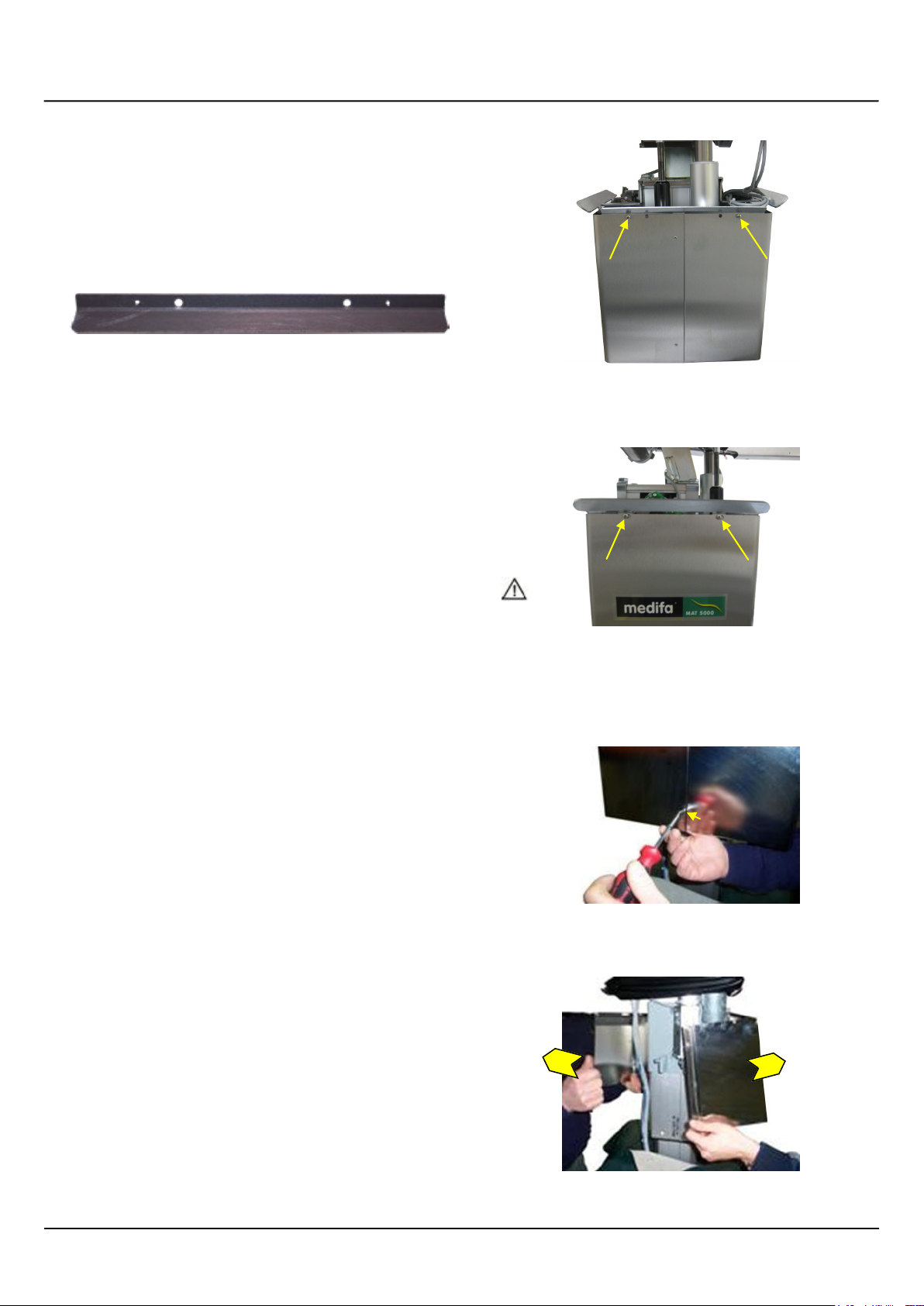
To remove the upper cover, loosen the screws on the back.
fig. 16: loosen upper column cover
medifa
®
medifa-hesse GmbH & Co. KG –Industriestraße 5 –D-57413 Finnentrop, Tel.: +49 (0) 2721-7177-0 –Fax: +49 (0) 2721-7177-77 7
fig. 17: loosen upper column cover
Bend the cover around the column, like you did with the
middle and lower covers in order to remove it.
Abb. 13: dismantle holders of expansion
bellow
Now dismantle the two holders of the expansion bellow from
the upper cover. For that, loosen the two screws on the front
and in the back.
fig. 15: loosen upper column cover
fig. 14: holder expansion bellow loose
Now the fastening screws on both sides can be removed as
well. If the holder hasn´t been removed yet, loosen the two
screws as well.
Attention:
Before removing the fastening screws on both sides, a
second person should secure the upper cover to prevent
it from falling down and causing secondary failures!
Service Manual - MAT 504220/ 504225 Operation Table
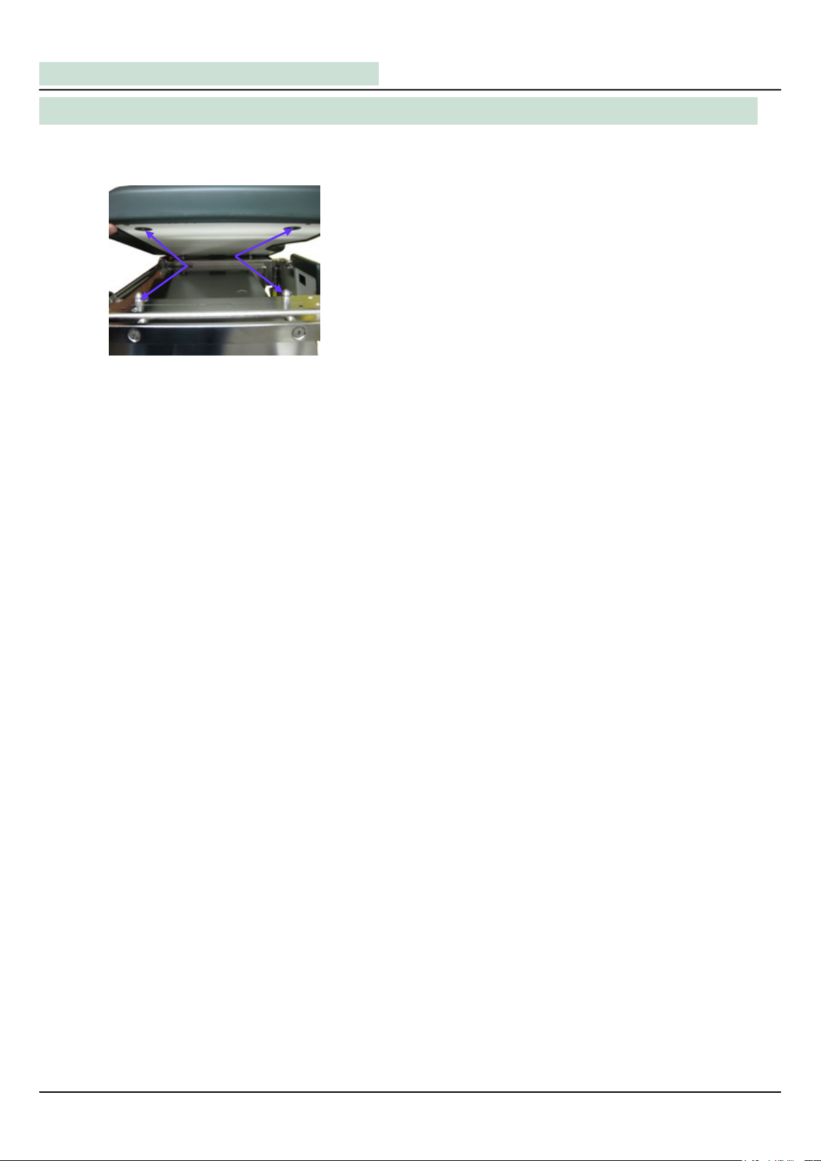
The upholstery of this operation table is just loosely fitted, to make cleaning and desinfection easy. Dismantle
the upholstery as follows:
To loosen the upholstery of the pelvis plate pull it upwards.
To remount the new upholstery put the notches on the back
onto the respective fixtures. Now push the upholstery against
the upper frame until it snaps in.
Repeat this procedure for mounting the back plate upholstery.
IV. Exchange of the Upholstery (Model 504220)
8
fig. 18: dismantle upholstery

Owing to the sliding table top, the upholsteries of this operation table model are screwed.
This leads to greater stability of the table top.
Dismantle the upholstery as follows:
Take off the upholstery of the pelvis plate by loosen the
fastening screws (4 screws) below the pelvis plate rods.
Now the upholstery can be taken off.
To loosen the upholstery of the back plate pull it upwards.
To remount the new upholstery put the notches on the back
onto the respective fixtures.
Now push the upholstery against the upper frame until it snaps in.
IV. Exchange of the Upholstery (Model 504225)
medifa
®
medifa-hesse GmbH & Co. KG –Industriestraße 5 –D-57413 Finnentrop, Tel.: +49 (0) 2721-7177-0 –Fax: +49 (0) 2721-7177-77 9
fig. 19: dismantle upholstery
fig. 20: dismantle upholstery
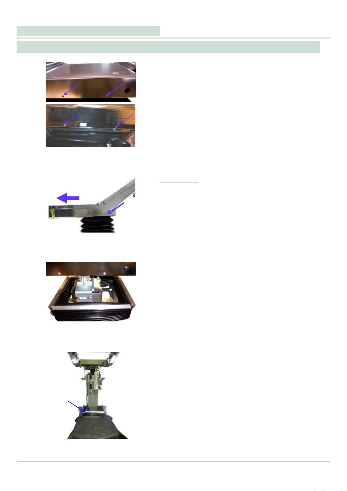
As soon as all screws are loosened, the expansion bellow is
supported by the remaining holders.
Service Manual - MAT 504220/ 504225 Operation Table
V. Replacement of the Motor for the Trendelenburg Adjustment
10
fig. 21+22: dismantle expansion bellow
To open up the motor for Trendelenburg adjustment, the
expansion bellow has to be dismantled from the upper cover.
For that, loosen the screws on the front and in the back as
well as in the back of the linkage box.
After that, remove both srews between pelvis plate rod and
linkage box.
This procedure has to be carried out both on the left and on
the right of the table!
Model 504225
To be able to loosen the screws of the expansion bellow, the
table top of the model 504225 (incl. sliding table top ) has to
be moved towards the foot plate. In addition, the back plate
has to be adjusted upwards.
The rear screw can be pulled out, because it is only hooked
in the linkage box.
fig. 24: Expansion bellow loosened
fig. 25: Expansion bellow loosened
The expansion bellow can now be pulled over the remaining
holders and put down on the base.
This is the easiest method for future repair works.
fig. 23: dismantle expansion bellow
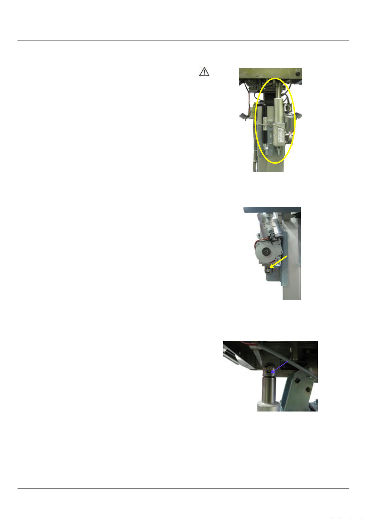
fig. 26: Motor for Trendelenburg
adjustment uncovered
medifa
®
medifa-hesse GmbH & Co. KG –Industriestraße 5 –D-57413 Finnentrop, Tel.: +49 (0) 2721-7177-0 –Fax: +49 (0) 2721-7177-77 11
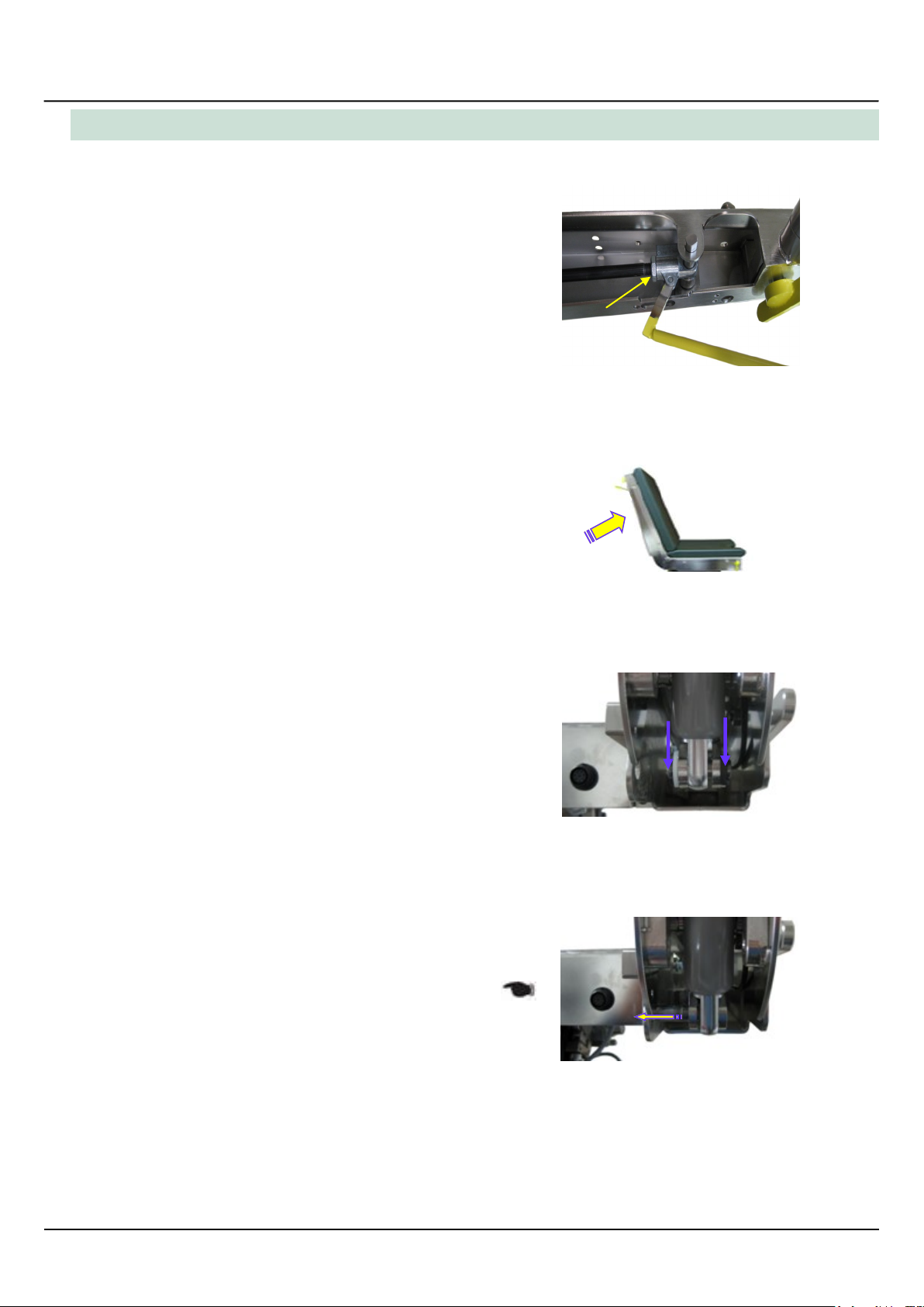
To remove the motor, pull the locking ring of the bolt. You will
find it on the lower suspension.
Now the motor only hangs on the upper suspension.
fig. 27: Motor for Trendelenburg adjustment
-remove lower suspension
To remove the motor from the upper suspension, remove the
locking ring of the suspension.
Now the motor can be pulled off to the side where the locking
ring has been removed.
Should the motor be stucked on the suspension, a second
person has to lift up the upper frame in the region of the head
plate. Now the suspension can be pushed aside.
Attention:
Before removing the motor for Trendelenburg ad-
justment, a second person should secure the upper co-
ver, because the built-in pull spring next to the motor will
tilt the upper frame into the Trendelenburg position.
fig. 2: Motor for Trendelenburg adjustment
-remove upper suspension
Service Manual - MAT 504220/ 504225 Operation Table
12
After removing the motor from the fixing points, the motor has
to be disconnected from the control.
Trace back the connection cable and remove the plug from
the control box.
Advice:
The right plugs can be looked up in the wiring diagram.
The control can be better achieved through the base plate
front cover. See also chapter „ Dismantling of the control pa-
nel“.
Advice:
To reintegrate the motor, the complete upper frame (table
top) has to be moved, with help of another person, into hori-
zontal position.
Now it is possible to fit the motor into the suspensions.
Dismantling & Replacement of the gas spring for
stabilization
To replace the pull spring (pull spring for stabilization) next to
the motor for Trendelenburg adjustment, the motor for Trend-
elenburg adjustment has to be dismantled first.
After that proceed as follows:
Attention:
During the work on the pull spring, a second person
shpuld secure the entire upper frame, because it is freely
pivoted on the Trendelenburg axis.
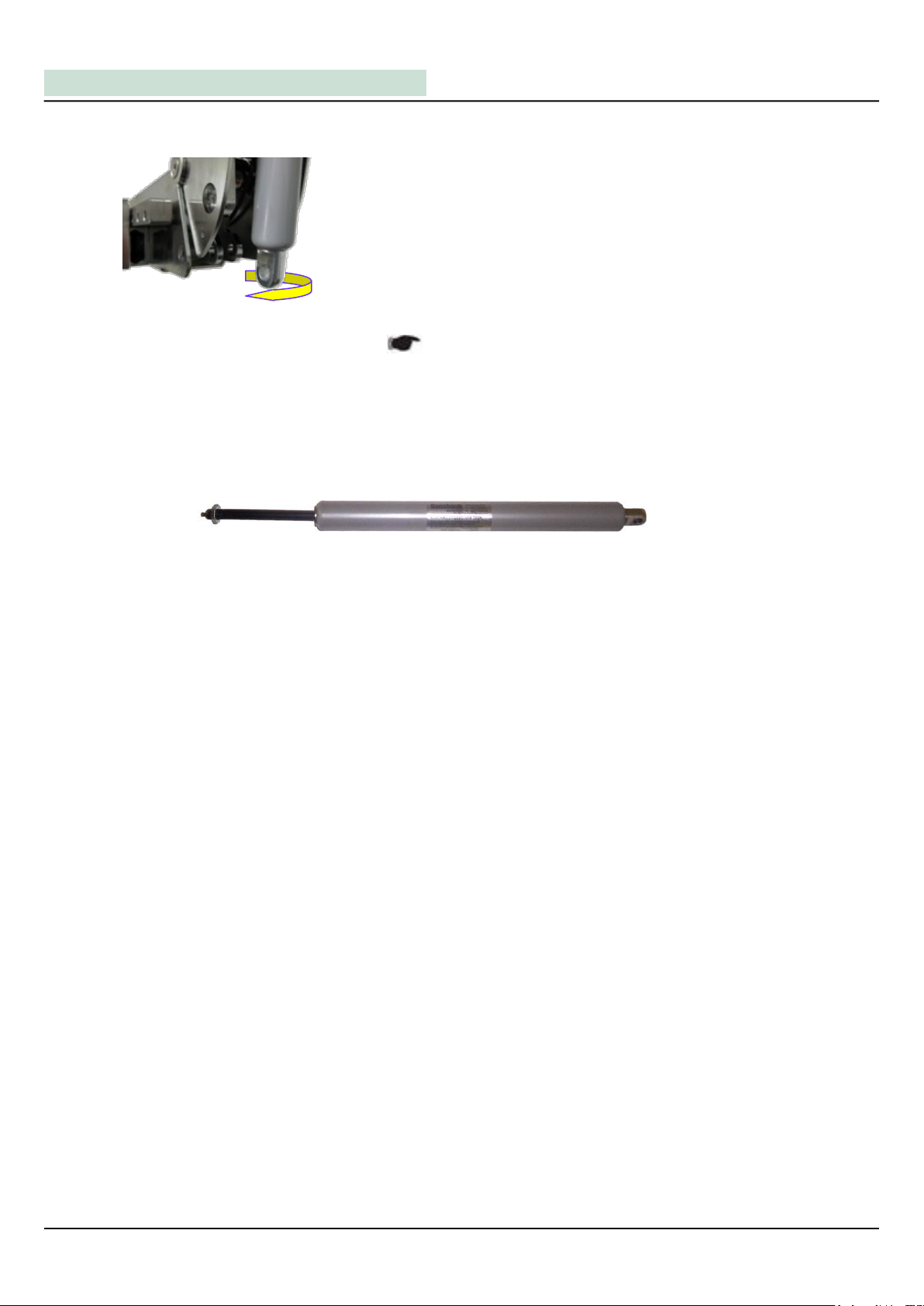
Pull the two locking rings (snap ring) on the upper and lower
end of the pull spring off the fastening bolt.
Now the pull spring can be pulled off the bolts!
fig. 29: Motor for Trendelenburg
adjustment dismantled
fig. 30: dismantle pull spring for
stabilization
fig. 31: dismantle pull spring for
stabilization
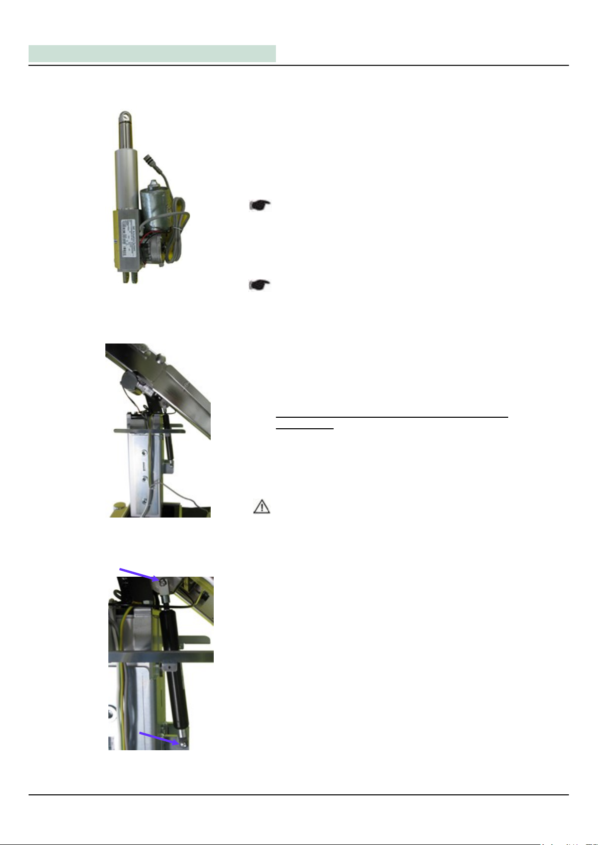
Replace the gas springs for back rest adjustment as follows:
At first, loosen the lock nuts on the upper end (top) of the gas
spring. With that, they can be unscrewed easily from the re-
lease button later.
Prick up the back rest as steep as possible.
Pull the two locking rings (snap rings) on both sides off the
fastening bolt of the gas spring on the lower suspension.
Now remove the bolt to be able to unscrew the gas spring
from the rod.
Advice:
This process should only even be carried out on one side.
Therefore, one gas spring should always be installed
correctly to avoid that the back rest falls down.
VI. Gas Springs for Back Rest Adjustment (Dismantling)
medifa
®
medifa-hesse GmbH & Co. KG –Industriestraße 5 –D-57413 Finnentrop, Tel.: +49 (0) 2721-7177-0 –Fax: +49 (0) 2721-7177-77 13
fig. 33:
dismantle gas spring for back
rest adjustment
fig. 34:
dismantle lower suspension
gas spring for back rest adjustment
fig. 35:
dismantle lower suspension
gas spring for back rest adjustment
fig. 32:
dismantle gas spring for back
rest adjustment
Advice:
Please note the montage advices of the gas springs in the
following chapter.
fig. 36: unscrew gas springs for back
rest adjustment
Service Manual - MAT 504220/ 504225 Operation Table
14
fig. 37: gas spring for back rest adjustment 750N LOOSE
Now the gas spring can be unscrewed from the release
button.
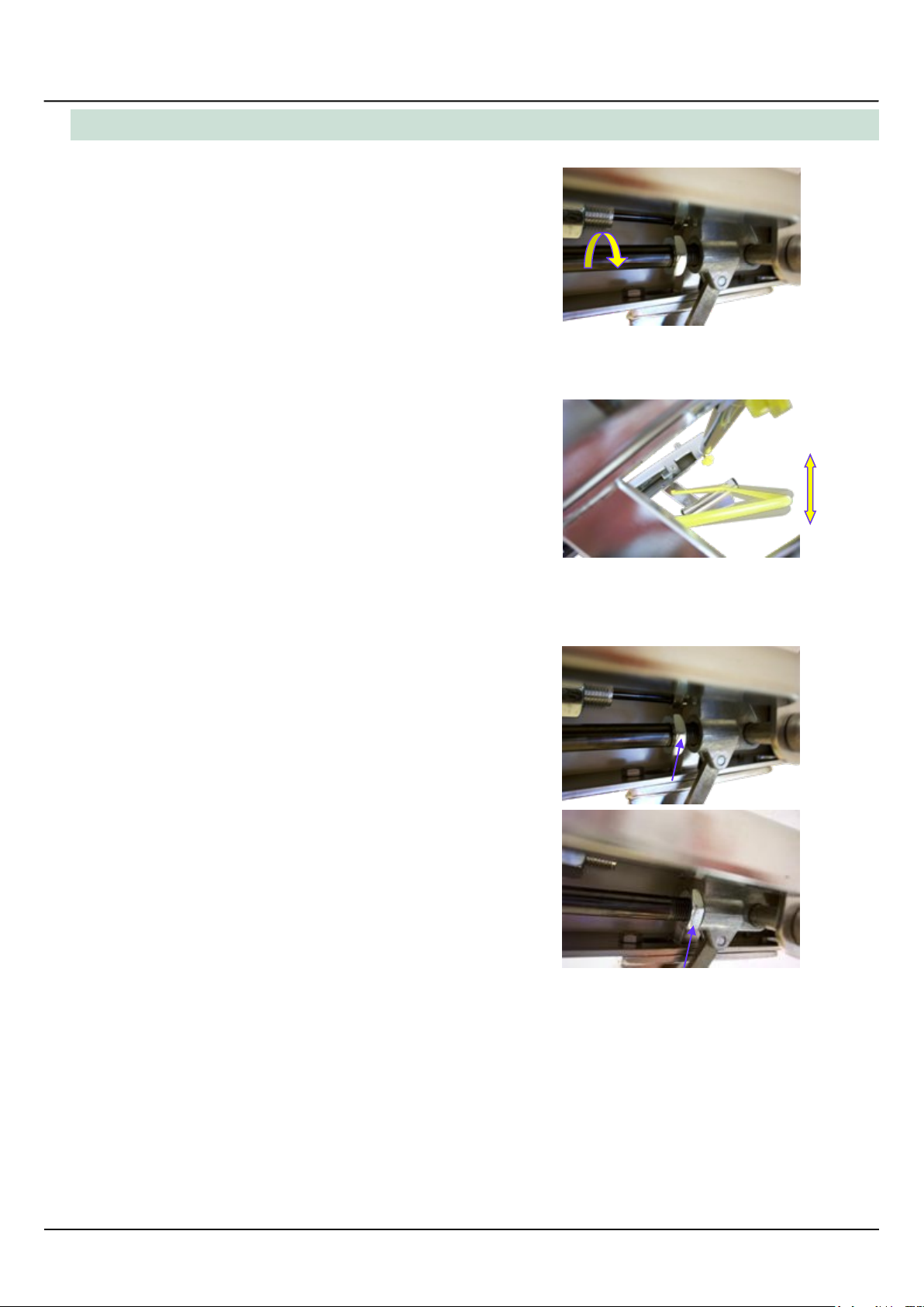
Please note that the new gas spring only should be screwed
in as far as the first resistance.
After that, the spring should be turned back by one turn
again, to provide a certain leeway of the release handle.
As soon as the gas springs are in the right position, fasten
the gas spring with the lock nut on the piston, to exclude an
inadvertent adjustment!
fig. 38: screw in gas springs for back
rest adjustment
fig. 39: adjust release handle for back
rest adjustment
fig. 40+41: fasten gas spring for back rest
adjustment
VI. Gas Springs for Back Rest Adjustment (Montage)
medifa
®
medifa-hesse GmbH & Co. KG –Industriestraße 5 –D-57413 Finnentrop, Tel.: +49 (0) 2721-7177-0 –Fax: +49 (0) 2721-7177-77 15
Service Manual - MAT 504220/ 504225 Operation Table
VI. Gas Springs for Back Rest Adjustment (Release Handle / Button)
16
fig. 42: Dismantling release handle back
rest
fig. 44+45: Dismantling release handle/
buttons back rest
fig. 43: adjust release handle of the
back rest
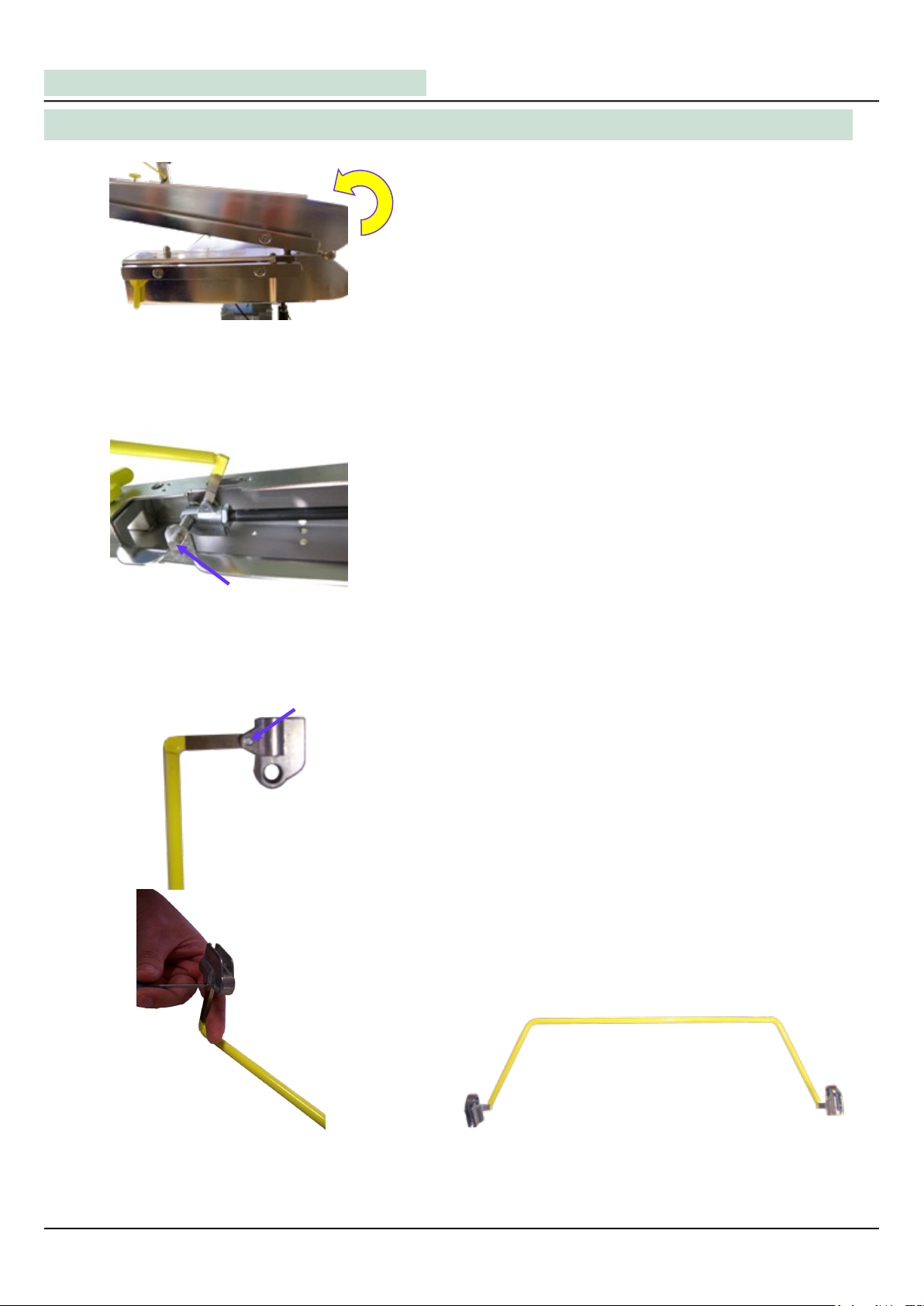
Remove the small fastening bolt with a punch from the inside
of the handle, to loosen the release buttons from the handle.
Please note that the bolt is manufactured conically, by instal-
ling a new handle!
Please proceed in the opposite order to that described for
dismantling, to install a new handle.
Defective release handles or buttons can be replaced as
follows:
Dismantle the gas springs as described before.
Now fold both back plate rods over the pelvis plate to obtain
a better accessibility.
Now the complete handle incl. both release buttons can be
dismantled. For that, loosen both fastening screws on the
end of both back plate rods.
fig. 46: Dismantling release handle back rest
VII. Dismantling of the complete Upper Frame (Model 504220)
medifa
®
medifa-hesse GmbH & Co. KG –Industriestraße 5 –D-57413 Finnentrop, Tel.: +49 (0) 2721-7177-0 –Fax: +49 (0) 2721-7177-77 17
fig. 50: Dismantling upper frame
fig. 48+49: Dismantling upper frame
After removing all 4 screws from the linkage box, the
entire upper frame can be taken off and put aside!
Attention:
Do not touch the release handle of the back plate.
This may lead to dangerous injuries!
fig. 51: Upper frame loose
To dismantle the upper frame, remove the co-
ver of the table. Also dismantle the expansion
bellow so that it lies on the base. Now dismant-
le the hand switch. The plug can simply be
unscrewed from the linkage box. Besides, the
plug of the hand switch connector has to be
removed, too.
For that, remove the both srews of the linkage box on both
sides of the plug.
After that, remove the upholstery of the pelvis plate.
In this way the linkage box will be uncovered.
The linkage box incl. rest of the upper frame is fixed on the
table base, by the now visible 4 screws.
Attention:
Before removing the last screws, a second person
should secure the upper frame to prevent it from falling
down!
fig. 47: Dismantling upper frame
Service Manual - MAT 504220/ 504225 Operation Table
VII. Dismantling of the complete Upper Frame (Model 504225)
18
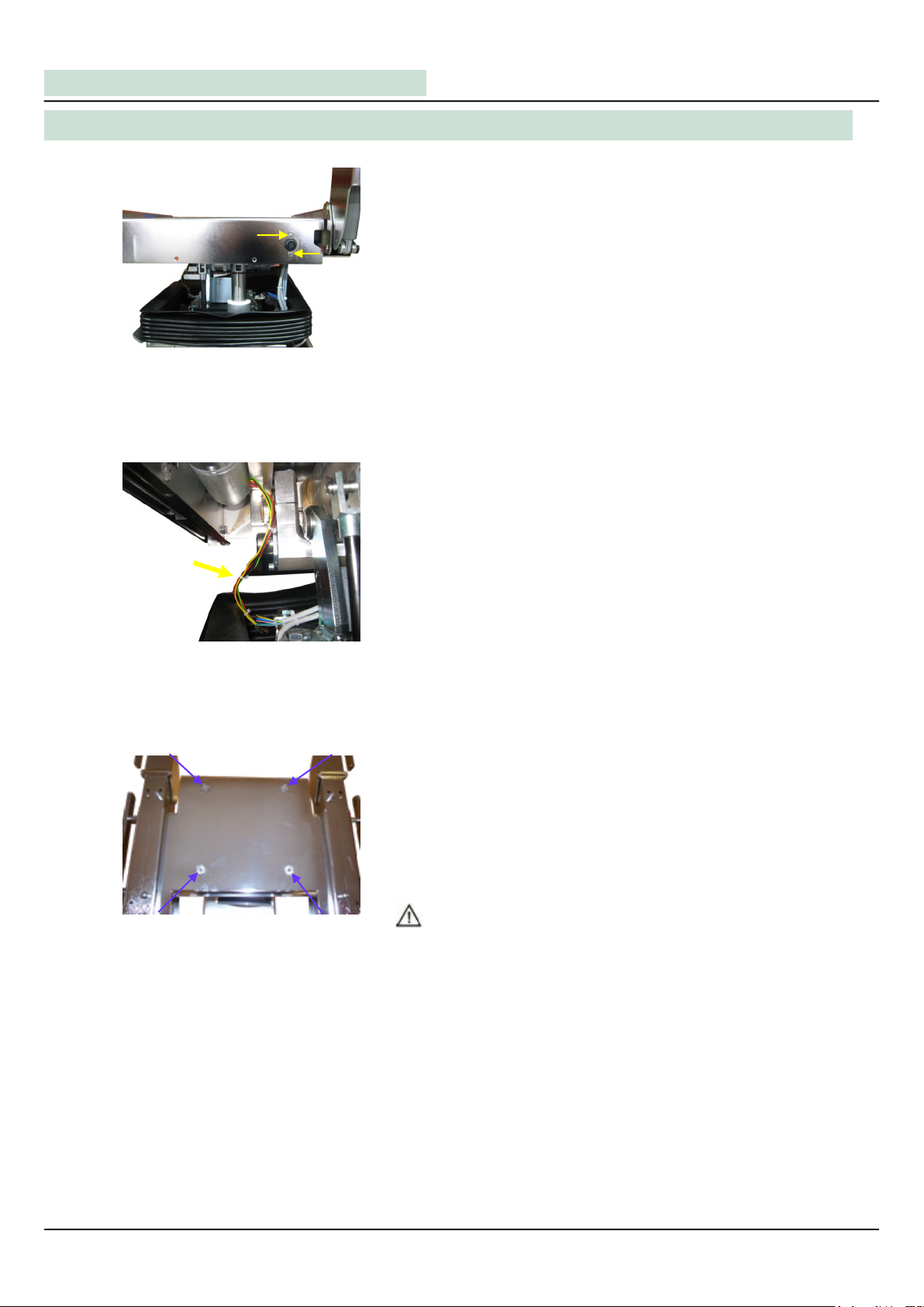
To dismantle the upper frame, remove the cover of the
table. Also dismantle the expansion bellow so that it lies
on the base and dismantle the pelvis plate
upholstery (as described before). Now dismantle the
hand switch. The plug can simply be unscrewed from
the linkage box. Besides, the plug of the hand switch
connector has to be removed, too.
For that, remove the two srews of the linkage box above an
below the plug.
The linkage box incl. rest of the upper frame is fixed on the
table base, by the 4 screws visible above the linkage box.
Before loosing the screws and removing the upper frame
from the table base, the cable of the shifiting engine has to
be disconnected from the control. Retrace the cables to the
control or look it up in the wiring diagram.
fig. 53: Shifting engine
fig. 54: Dismantling upper frame
fig. 52: Plug hand switch connector
Now loosen the 4 screws on the top of the linkage box, which
fix the upper frame on the table base.
Attention:
Before removing the screws, a second person should
secure the upper frame to prevent it from falling down!

medifa
®
medifa-hesse GmbH & Co. KG –Industriestraße 5 –D-57413 Finnentrop, Tel.: +49 (0) 2721-7177-0 –Fax: +49 (0) 2721-7177-77 19
After removing all 4 screws from the linkage box, the
entire upper frame can be taken off and put aside!
Attention:
Do not touch the release handle of the back plate
This may lead to dangerous injuries!
fig. 56: Dismantling upper frame
fig. 57: Upper frame loose
fig. 55: Dismantling upper frame

Service Manual - MAT 504220/ 504225 Operation Table
VIII. Replacement of the Distribution Panel
fig. 58+59: Replacement of the
distribution panel
To replace the distribution panel, the expansion bellow has to
be loosen (as described in chapter III of this manual).
When loosen, the inside of the table is visible and both faste-
ning screws have to be removed from the distribution panel.
In case of model 504225 with shifting function, the Sub-D
plug and the cable tie on the top of the distribution panel
have to be removed.
fig. 60: Opening of the distribution panel
After dismantling, the distribution panel has to be opened.
For that, remove the 4 screws on the back of the panel.
fig. 61: Replacement of the distribution
panel.
Advice:
Take care of the connections of the cables by replacing the
distribution panel. Remember the order or have a look in the
wiring diagram.
Now loosen the 4 plugs in the panel, to uncover them
completely.
Please proceed in the opposite order to that described for
dismantling, to install a new distribution panel.
20
This manual suits for next models
1
Table of contents
Other Medifa Medical Equipment manuals


Popular Medical Equipment manuals by other brands


Invacare
Invacare Birdie EVO Series user manual

baxter
baxter DUPLOSPRAY Quick reference manual

CardiAid
CardiAid CT0207RS User Manual and Introduction to the Device

Nonin
Nonin Sensmart H500 Operator's manual

Integra
Integra MAYFIELD Head Clamp A2079 Instructions for use

Storz
Storz VITOM 3D Instructions for use