Medifa 6000 User manual

medifa 6000
Mobile operating tables
Service manual
Version: 2.0


Table of contents
Service manual for medifa 6000 mobile operating tables, version 2.0
Table of contents
1.Important information.................................................................................................................. 5
1.1 Revision history . . . . . . . . . . . . . . . . . . . . . . . . . . . . . . . . . . . . . . . . . . . . . . . . . . . . . . . . . . . . . . . . . . . . . . 5
1.2 CE marking . . . . . . . . . . . . . . . . . . . . . . . . . . . . . . . . . . . . . . . . . . . . . . . . . . . . . . . . . . . . . . . . . . . . . . . . . . 5
1.3 Conformity . . . . . . . . . . . . . . . . . . . . . . . . . . . . . . . . . . . . . . . . . . . . . . . . . . . . . . . . . . . . . . . . . . . . . . . . . . 5
1.4 Manufacturer and distributor . . . . . . . . . . . . . . . . . . . . . . . . . . . . . . . . . . . . . . . . . . . . . . . . . . . . . . . . . 5
1.5 Copyright Statement . . . . . . . . . . . . . . . . . . . . . . . . . . . . . . . . . . . . . . . . . . . . . . . . . . . . . . . . . . . . . . . . . 5
1.6 Notes for the service technician . . . . . . . . . . . . . . . . . . . . . . . . . . . . . . . . . . . . . . . . . . . . . . . . . . . . . . . 6
1.7 Definition of the alignment . . . . . . . . . . . . . . . . . . . . . . . . . . . . . . . . . . . . . . . . . . . . . . . . . . . . . . . . . . . 6
2.Used symbols................................................................................................................................. 7
3.Preparing the operating table ...................................................................................................... 8
4.Components column / top frame ................................................................................................. 9
4.1 Removal of column cladding including column keyboard board . . . . . . . . . . . . . . . . . . . . . . . . . . 9
4.2 Releasing the bellows . . . . . . . . . . . . . . . . . . . . . . . . . . . . . . . . . . . . . . . . . . . . . . . . . . . . . . . . . . . . . . . 12
4.3 Checking the oil level. . . . . . . . . . . . . . . . . . . . . . . . . . . . . . . . . . . . . . . . . . . . . . . . . . . . . . . . . . . . . . . . 13
4.4 Removing the padding plates . . . . . . . . . . . . . . . . . . . . . . . . . . . . . . . . . . . . . . . . . . . . . . . . . . . . . . . . 14
4.5 Replacing the distributor board . . . . . . . . . . . . . . . . . . . . . . . . . . . . . . . . . . . . . . . . . . . . . . . . . . . . . . 15
4.5.1 Cable assignment on the distributor board . . . . . . . . . . . . . . . . . . . . . . . . . . . . . . . . . . . . . . . . . . . . . . . . . . . . 15
4.6 Replacing the distributor board . . . . . . . . . . . . . . . . . . . . . . . . . . . . . . . . . . . . . . . . . . . . . . . . . . . . . . 16
4.6.1 Displacement encoder system connection of height adjustment . . . . . . . . . . . . . . . . . . . . . . . . . . . . . . . . . 16
4.6.2 Displacement encoder system of longitudinal displacement . . . . . . . . . . . . . . . . . . . . . . . . . . . . . . . . . . . . . 17
4.6.3 Displacement encoder system of the Trendelenburg adjustment . . . . . . . . . . . . . . . . . . . . . . . . . . . . . . . . . 18
4.6.4 Displacement encoder system of lateral adjustment. . . . . . . . . . . . . . . . . . . . . . . . . . . . . . . . . . . . . . . . . . . . 19
4.6.5 Displacement encoder system of the back plate adjustment. . . . . . . . . . . . . . . . . . . . . . . . . . . . . . . . . . . . . 20
4.6.5.1 Replacement on model 601700 . . . . . . . . . . . . . . . . . . . . . . . . . . . . . . . . . . . . . . . . . . . . . . . . . . . . . . . . . . . . . . 20
4.6.5.2 Replacement on models 601120 and 601820 . . . . . . . . . . . . . . . . . . . . . . . . . . . . . . . . . . . . . . . . . . . . . . . . . . 22
4.6.5.3 Replacement on model 601920 . . . . . . . . . . . . . . . . . . . . . . . . . . . . . . . . . . . . . . . . . . . . . . . . . . . . . . . . . . . . . . 24
5.6.6 Displacement encoder system of the leg plate adjustment (item no: 601920) . . . . . . . . . . . . . . . . . . . . . 25
4.6.7 Displacement encoder system of the upper back plate adjustment on models 601700 and 601820 . . 27
4.7 Replacing the hydraulic unit . . . . . . . . . . . . . . . . . . . . . . . . . . . . . . . . . . . . . . . . . . . . . . . . . . . . . . . . . 29
4.8 Replacing the batteries . . . . . . . . . . . . . . . . . . . . . . . . . . . . . . . . . . . . . . . . . . . . . . . . . . . . . . . . . . . . . . 30
5.Components of base.................................................................................................................... 32
5.1 Replacing the mains input fuse. . . . . . . . . . . . . . . . . . . . . . . . . . . . . . . . . . . . . . . . . . . . . . . . . . . . . . . 32
5.2 Replacing the power input module . . . . . . . . . . . . . . . . . . . . . . . . . . . . . . . . . . . . . . . . . . . . . . . . . . . 32

4Service manual for medifa 6000 mobile operating tables, version 2.0
5.3 Replacing the battery fuse . . . . . . . . . . . . . . . . . . . . . . . . . . . . . . . . . . . . . . . . . . . . . . . . . . . . . . . . . . . 32
5.4 Replacing the control unit . . . . . . . . . . . . . . . . . . . . . . . . . . . . . . . . . . . . . . . . . . . . . . . . . . . . . . . . . . . 33
5.6 Replacing the external charge control. . . . . . . . . . . . . . . . . . . . . . . . . . . . . . . . . . . . . . . . . . . . . . . . . 35
5.7 Replacing the 5th wheel . . . . . . . . . . . . . . . . . . . . . . . . . . . . . . . . . . . . . . . . . . . . . . . . . . . . . . . . . . . . . 36
5.8 Replacing the batteries . . . . . . . . . . . . . . . . . . . . . . . . . . . . . . . . . . . . . . . . . . . . . . . . . . . . . . . . . . . . . . 38
5.9 Replacing the twin swivel castors . . . . . . . . . . . . . . . . . . . . . . . . . . . . . . . . . . . . . . . . . . . . . . . . . . . . 40
6.Calibration ................................................................................................................................... 42
7.Possible malfunction and causes................................................................................................ 43
8.Spare parts lists ........................................................................................................................... 46
8.1 Spare parts base . . . . . . . . . . . . . . . . . . . . . . . . . . . . . . . . . . . . . . . . . . . . . . . . . . . . . . . . . . . . . . . . . . . . 46
8.2 Spare parts column . . . . . . . . . . . . . . . . . . . . . . . . . . . . . . . . . . . . . . . . . . . . . . . . . . . . . . . . . . . . . . . . . 47
8.3 Spare parts of manual switch . . . . . . . . . . . . . . . . . . . . . . . . . . . . . . . . . . . . . . . . . . . . . . . . . . . . . . . . 48
8.4 Spare parts upper frame . . . . . . . . . . . . . . . . . . . . . . . . . . . . . . . . . . . . . . . . . . . . . . . . . . . . . . . . . . . . . 48
8.4.1 Top frame on model 601120 . . . . . . . . . . . . . . . . . . . . . . . . . . . . . . . . . . . . . . . . . . . . . . . . . . . . . . . . . . . . . . . . . 48
8.4.2 Top frame on model 601700 . . . . . . . . . . . . . . . . . . . . . . . . . . . . . . . . . . . . . . . . . . . . . . . . . . . . . . . . . . . . . . . . . 49
8.4.3 Top frame on models 601820 . . . . . . . . . . . . . . . . . . . . . . . . . . . . . . . . . . . . . . . . . . . . . . . . . . . . . . . . . . . . . . . . 50
8.4.4 Top frame on model 601920 . . . . . . . . . . . . . . . . . . . . . . . . . . . . . . . . . . . . . . . . . . . . . . . . . . . . . . . . . . . . . . . . . 51
8.5 Spare parts head plate - Item No.: 61144 SF . . . . . . . . . . . . . . . . . . . . . . . . . . . . . . . . . . . . . . . . . . . 52
8.6 Spare parts of leg plates - Item No. 61615SF . . . . . . . . . . . . . . . . . . . . . . . . . . . . . . . . . . . . . . . . . . 53
8.7 Spare parts of leg plates - 61616SF . . . . . . . . . . . . . . . . . . . . . . . . . . . . . . . . . . . . . . . . . . . . . . . . . . . 54
8.8 Spare parts upper back plate 61250SF . . . . . . . . . . . . . . . . . . . . . . . . . . . . . . . . . . . . . . . . . . . . . . . . 55
9.Hydraulic diagram ....................................................................................................................... 56
9.1 Hydraulic diagram 601120. . . . . . . . . . . . . . . . . . . . . . . . . . . . . . . . . . . . . . . . . . . . . . . . . . . . . . . . . . . 56
9.2 Hydraulic diagram 601700, 601820. . . . . . . . . . . . . . . . . . . . . . . . . . . . . . . . . . . . . . . . . . . . . . . . . . . 58
9.3 Hydraulic diagram 601920. . . . . . . . . . . . . . . . . . . . . . . . . . . . . . . . . . . . . . . . . . . . . . . . . . . . . . . . . . . 60
10.Wiring diagram.......................................................................................................................... 62
11.Maintenance plan ..................................................................................................................... 63
Table of contents

5Service manual for medifa 6000 mobile operating tables, version 2.0
Important information
1.1 Revision history
Version Date Reason or modification of publication
1.0 01/2015 First edition
2.0 08/2020 Summary of all models
1. Important information
1.2 CE marking
This product is a Class 1 medical product according to the European Directive 93/42/EEC on medical products. It complies
with the version of this Directive applicable at the time of being placed on the market.
1.3 Conformity
The manufacturer shall declare the conformity of this product with the essential requirements as per the Medical Device
Directive (MDD) according to annex 1 as well as the execution of a conformity assessment procedure required for Class 1
products as per MDD according to annex 7 and shall document this through the CE label.
1.4 Manufacturer and distributor
medifa GmbH & Co. KG
Industriestraße 5
57413 Finnentrop
Germany
Phone +49 2721 7177-0
Fax no. +49 2721 7177-255
info@medifa.com
www.medifa.com
1.5 Copyright Statement
This repair manual including all illustrations are subject to copyright. The transmission and reproduction of this document as
well as the exploitation and communication of its contents are - unless expressly permitted - are prohibited. Contraventions
shall impose and obligation to compensation for damages. All rights reserved in case of a patent grant or utility model
registration.
We are constantly working on the further development of our products. Please understand that we must reserve the right to
change the scope of delivery in shape, equipment and technology at any time.
Reproduction, duplication or translation of the original repair manual, even in part, is not permitted without written consent
from medifa.
All rights according to the copyright law are expressly reserved by medifa. medifa shall only be responsible for the safety-
related properties of this device within the framework of the legal regulations if maintenance, servicing and changes to this
device are carried out by medifa itself or a representative in accordance with instructions.

6Service manual for medifa 6000 mobile operating tables, version 2.0
Important information
1.6 Notes for the service technician
This repair manual is intended for trained service and maintenance personnel. If a problem occurs that cannot be solved with
the help of this repair manual, please contact our technical service department.
Phone +49 (0) 2721 7177-410
Repairs may only be carried out by service personnel trained by medifa. To this end,
medifa offers service training courses. This repair manual also serve as training documentation.
Repairs beyond the scope of this repair manual may only be carried out after consultation with medifa or must be carried out
by medifa GmbH & Co. KG.
After all repairs or adjustments, a function check must be carried out by the service technician. The device may only be
handed over to the customer in a tested condition with full functionality.
1.7 Definition of the alignment
Bottom side
Top side
Right side as seen by the patient
Left side as seen by the patient
Figure 1
Front side
Back side
7Service manual for medifa 6000 mobile operating tables, version 2.0
2. Used symbols
In this repair manual, various note and safety symbols are used to highlight particularly relevant information.
Safety instructions
HAZARD
HAZARD indicates an imminently hazardous situation which, if not avoided, will result in death or serious injury.
WARNING
WARNING indicates a potentially hazardous situation which, if not avoided, could result in death or serious injury.
CAUTION
CAUTION indicates a potentially hazardous situation which, if not avoided, could result in minor or moderate injury.
WARNING
Indication of a harmful situation with the possible consequences: the device or something in its vicinity could be damaged.
Used symbols

8Service manual for medifa 6000 mobile operating tables, version 2.0
3. Preparing the operating table
Before you start repair work, you must ensure that the necessary hygienic conditions are ensured at the place of work. If you
are unsure about how to prevent infection, kindly consult with the doctor in charge!
The repairs may only be effected if the protection against infection is assured!
Before starting the repair work, the following preparatory steps should be carried out:
1.
CAUTION
Danger of infection!
Before starting repair work, have the medical institution confirm that all necessary protective measures against infection
have been taken!
2.
CAUTION
Risk of injury caused by the operating table rolling away!
Apply the brakes on the operating table!
3. Move the upper frame to the zero position (horizontal position).
4. Remove all accessories and keep them safely.
HAZARD
Danger of electric shock!
During repair work, you must keep the operating table in a zero-voltage state, otherwise there is a risk of electric shock.
Proceed as follows:
• Turn off the operating table
• Remove the mains plug from the socket
• Remove the battery fuse from the base.
HAZARD
Danger of injury!
After each repair, an electrical safety test must be carried out in accordance with 0751-1 of DIN VDE German Institute for
Standardisation, German electrical engineers association).
Important information
9
ww
ee
ee
ww
rr
qq
qq
ww
ttyy
Service manual for medifa 6000 mobile operating tables, version 2.0
4. Components column / top frame
Components column / top frame
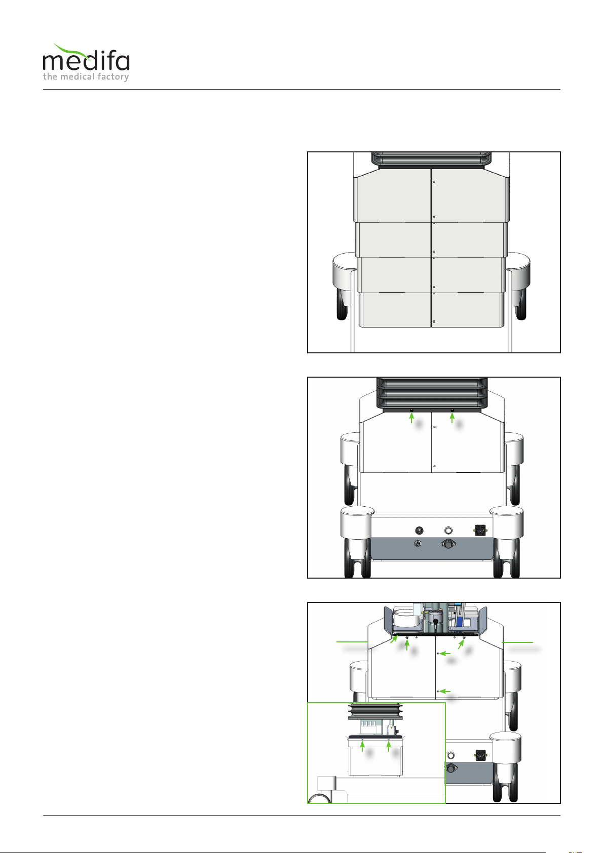
To remove the column cladding on the operating table,
the height adjustment of the operating table is first
moved to the lowest position.
This can be done using the column keypad or the manual
switch.
Always switch off the operating table afterwards,
disconnect the mains plug from the socket and remove
the battery fuse from the base so that the base is zero-
voltage.
The next step is to remove the 12 screws on the upper
column cladding (see Fig. 4).
4 screws [2] are located on the top side, 4 more on the
bottom side [2] and 2 screws [3] both on the front and
the back. When the screws [2] are loosened, the bellows
retaining brackets [4] are released at the same time.
When all screws have been removed and the bellows
retaining brackets have been dismantled, the left-hand
upper cladding half [5] can now be removed. To dismantle
the right-hand top cladding half [6], the ribbon cable
must first be removed from the column keyboard board.
Figure 2
Figure 3
Figure 4
To remove the top cladding, the bellows must now be
detached.
To detach the bellows from the top cladding, first remove
four expanding rivets [1] all around. Use a small slotted
screwdriver or suitable flat-nose pliers to do this.
Then the bellows can be slipped over the bellows
retaining brackets.
4.1 Removal of column cladding including column keyboard board
10
uu
uu
iiii
iiii
Service manual for medifa 6000 mobile operating tables, version 2.0
To this end, the supply connection cable must be removed
from the housing and the two screws[7] loosened.
CAUTION: Be careful when dismantling the column
keyboard board, because the ribbon cable of the board
can be damaged by incorrect handling.
Figure 5
Components column / top frame
The next step is to remove the four screws[8] on the back
of the housing of the board.
To do this, turn the housing upside down so that the four
screws marked can be removed from the cover.
WARNING
Do not lift the cover of the housing under extreme force and follow the last step of the repair instructions to avoid damag-
ing the supply interface of the board.
Figure 6

11
oo
aa
aa
ss
ss
dd
Service manual for medifa 6000 mobile operating tables, version 2.0
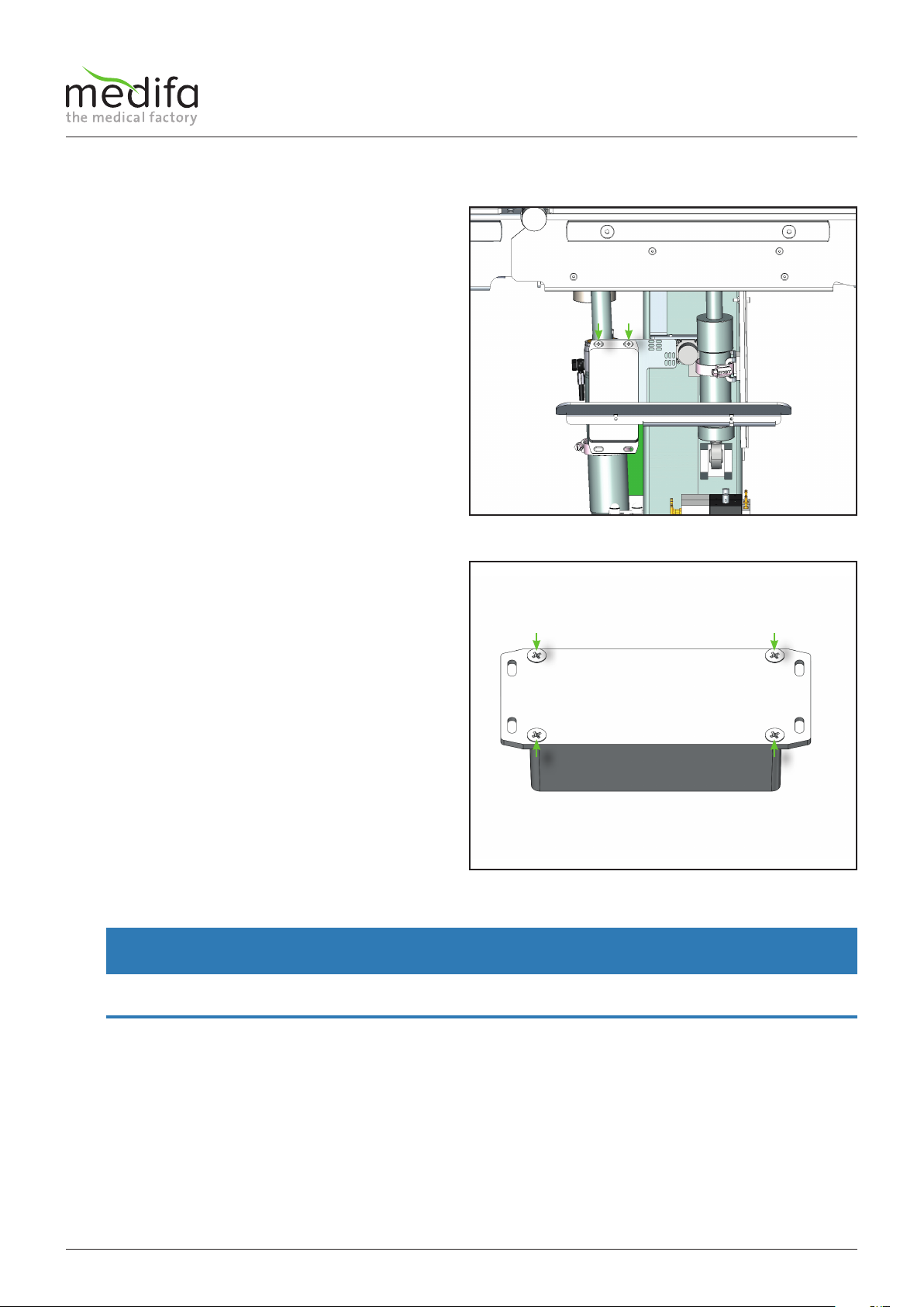
To remove the upper middle cladding, first remove the
two screws [10] at the front and back.
Finally, the cladding halves can be removed.
Proceed the same way with the middle cladding.
To remove the bottom cladding,
first remove the screws [11 and 12] on the bottom side,
top side, front and back side.
Finally, the cladding halves can be removed.
Figure 8
Figure 9
To remove the housing, you must now pull the cover
forward and lift the rear part of the cover. Be careful
since if you do not follow this order, you may damage the
power supply interface [9] of the board.
If the cover is removed, you can now remove the ribbon
cable.
Figure 7
Components column / top frame

12 Service manual for medifa 6000 mobile operating tables, version 2.0
To loosen the bellows, the two screws on the top and
bottom side of the joint box must be removed.
4.2 Releasing the bellows
Then the lateral fixing plates must be loosened. Remove
all screws on the left and right side.
Now the bellows can be pulled over the two brackets and
placed on the base.
The entire technical equipment of the table can now be
easily handled.
Figure 10
Figure 11
Components column / top frame

13
qq
Service manual for medifa 6000 mobile operating tables, version 2.0
4.3 Checking the oil level
To check the oil level, you should first expose the table column as described in chapter
“Removal of the column cladding” described.
Proceed as follows to check the oil level in the hydraulic system:
1. Move the table to the lowest position.
2. In addition, tilt the table to the head-down position, as far as this is possible without any collision.
3. Then tilt the table to the left (as seen by the patient), as far as this is possible without any collision.
4. Fold the backrest down, as far as this is possible without any collision.
5. For the 601920 operating table, you must also lower the leg plates, as far as this is possible without any collision.
6. On operating tables 601700 and 601920 you must also lower the upper backrest, as far as this is possible without any
collision.
All installed cylinders are now largely retracted. This means that the highest possible filling level in the oil tank must be
ensured! Ideally the oil level is approx. 20 mm below the upper tank cap
WARNING
Avoid collisions between the top frame and the base!
Serious damage can occur if all the previously described functions are moved to the end position!
To top up the oil, remove the filler cap [1] and top up the
hydraulic oil via a funnel!
Oil type: ARAL VITAM EN 32
Figure 12
Components column / top frame

14
qq
qq
ww
ww
ww
ww
qq
qq
Service manual for medifa 6000 mobile operating tables, version 2.0
4.4 Removing the padding plates
In order to remove the padding plates of the pool, it is
necessary to remove the four spigots [1].
The padding plate of the lower back, can be removed by
removing the four screws [2].
Depending on the model, mortise and tenon elements
are also screwed to the padding plate of the lower back.
The padding plates are mounted in the reverse order
Components column / top frame
Figure 13
15
qq
qq
Service manual for medifa 6000 mobile operating tables, version 2.0
height tilt leg L
trend reloc leg R back
X2
w b g
w b g
g b w
w b g
g b w
w b g g b w
X4 X6
X3 X5 X7 X1
leg R2 leg R1 leg L1 leg L2
y g w b w b y g
X12 X13 X14 X15
X23
X11
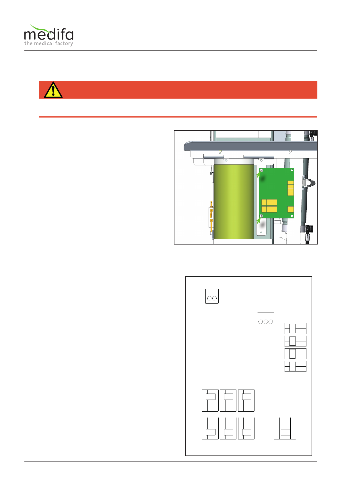
4.5 Replacing the distributor board
To remove the distributor board, the column cladding
must be removed (see chapter Removing the column
cladding).
Document the position of the cables before starting the
disassembly in order to be able to reassemble them later
in their original position.
First remove the electrical wiring. It proves helpful to
document the position of the wiring before dismantling
in order to be able to return it to its original position
afterwards. Then remove the two screws[1] to remove the
distributor board.
The assembly is carried out in the reverse order. Please
note that after the installation of the new distributor
board, the calibration program must be carried out (see
chapter Calibration).
The cable assignment can be taken from the cable diagram.
HAZARD
Danger of electric shock!
Before starting to replace the distributor board, you must put the operating table in a zero-voltage state, otherwise there is a
risk of electric shock.
Components column / top frame
Figure 14
x1 = back = displacement encoder system connection for lower
back plate
x2 = height = displacement encoder system connection for
height
x3 = trend = displacement encoder system connection for
Trendelenburg
x4 = tilt = displacement encoder system connection for lateral
x5 = reloc =displacement encoder system connection for
moveability
x6 = leg L = displacement encoder system connection for left
leg plate
x7 = leg R = displacement encoder system connection for right
leg plate
x12 = leg R1 = Switch in right leg plate receptacle, top
(for right split leg plate)
x13 = leg R2 = Switch in right leg plate receptacle, bottom
(for extension device)
x14 = leg L1 = Switch in left leg plate receptacle, top
(for left split leg plate)
x15 = leg L2 = Switch in left leg plate receptacle, bottom
(for extension device)
x23 = 24V connection (cable T04647 see cable diagram)
x11 = diagnostic connection (cable T04651 see cable diagram)
w= White
b = Brown
g = Green
y = Yellow
4.5.1 Cable assignment on the distributor board
16
ww
ww
qq
Service manual for medifa 6000 mobile operating tables, version 2.0
4.6 Replacing the distributor board
To replace the displacement encoder system of the
height adjustment, it is necessary to remove the column
cladding.
Please refer to the relevant chapters of this repair manual
for instructions!
After the column cladding has been removed, the bracket
must now be loosened by means of the two screws [1]
and carefully guided towards the potentiometer. When
installing the wire-rope pull potentiometer, also make
sure that the wire-rope does not snap upwards. This can
damage the wire-rope potentiometer.
Now the two screws [2] can be removed from the
lifting column and the displacement encoder can be
dismounted. Then remove the wire-rope pull eyelet from
the mounting bracket.
In the next step the wiring must be traced back to the
connection point and removed from the distributor
board. Document the position of the cables and the cable
ties before starting the disassembly. When installing the
new cable, replace the cable ties in their original position.
Now the displacement encoder system can be replaced.
The installation of the new displacement encoder system
is carried out in the reverse order, kindly note that after
the installation of the new displacement encoder system,
the calibration programme must be carried out (see
chapter calibration).
The cable assignment can be taken from the cable
diagram.
4.6.1 Displacement encoder system connection of height adjustment
Components column / top frame
Figure 15
Figure 16
WARNING
When installing the wire-rope pull potentiometer, also make sure that the wire-rope does not snap upwards. This can dam-
age the wire-rope potentiometer.
WARNING
When installing the wire-rope pull potentiometer, also make sure that the wire-rope does not snap upwards. This can dam-
age the wire-rope potentiometer.

17
ww
qq
rrtt
ee
Service manual for medifa 6000 mobile operating tables, version 2.0
First loosen the screw [1] at the end of the
displacement encoder system and disassemble the
plastic cover [2].
Now remove the screws [3] for fastening the tab for the
displacement encoder system for the displacement under
the right pelvic rail.
Now the screw [4] can be removed by exposing the
contacts and then the screw[5] can be removed.
In the next step the wiring must be traced back to the
connection point and removed from the distributor
board. Document the position of the cables and the cable
ties before starting the disassembly. When installing the
new cable, replace the cable ties in their original position.
Now the displacement encoder system can be replaced.
The installation of the new displacement encoder system
is carried out in the reverse order, kindly note that after
the installation of the new displacement encoder system,
the calibration programme must be carried out (see
chapter calibration).
The cable assignment can be taken from the cable
diagram.
Figure 17
Figure 18
4.6.2 Displacement encoder system of longitudinal displacement
Components column / top frame
18
ww
rr
ee
qq
tt
Service manual for medifa 6000 mobile operating tables, version 2.0
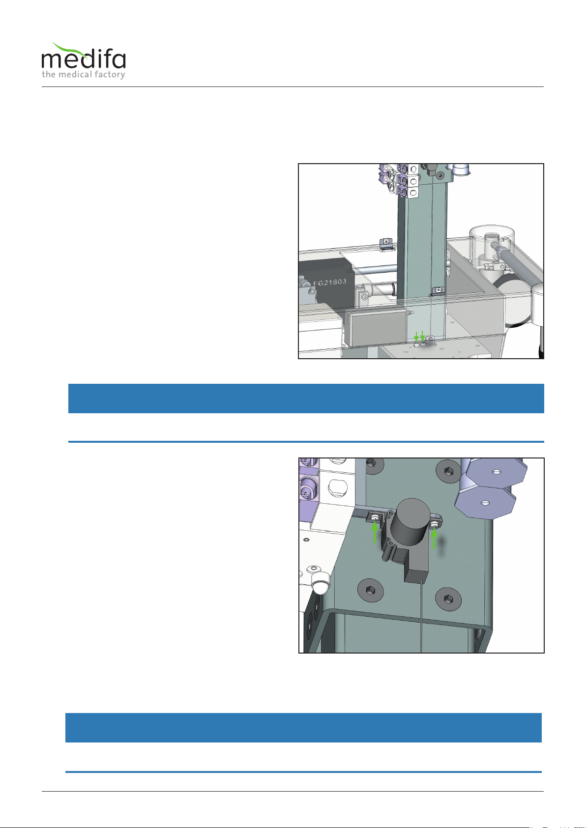
4.6.3 Displacement encoder system of the Trendelenburg adjustment
To replace the displacement measuring system of the
Trendelenburg adjustment, the column cladding must be
removed.
You will find instructions for this in the corresponding
chapters of this manual!
Before dismantling the displacement encoder system, it
is important to place a mark [1] on the cylinder so that
when the new displacement encoder is installed, the
position of the driver can be adjusted at the same height
to the cylinder.
After this, the driver [2] and the hose clamp [3] must be
removed.
WARNING
The driver must be installed in its original position during assembly.
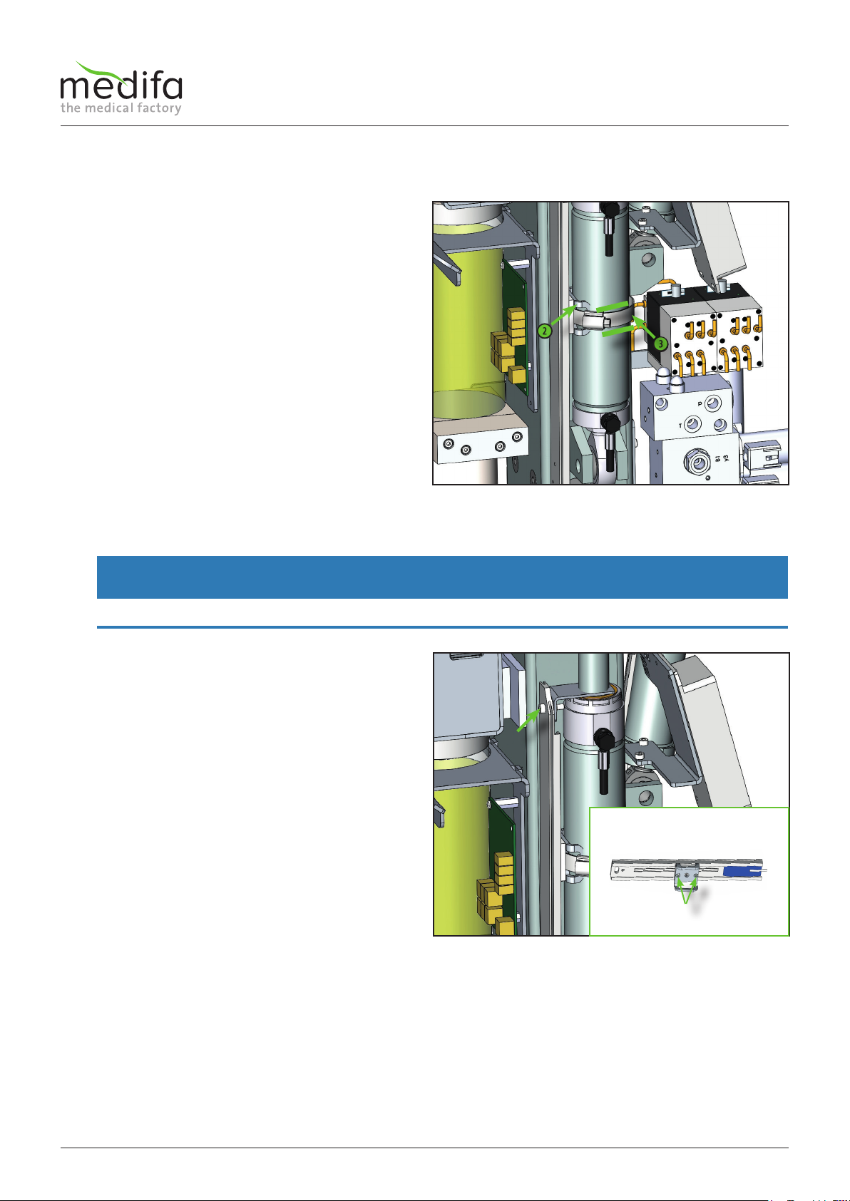
Now the screw connection [4] of the displacement
encoder system can be loosened and the system can be
placed on the base.
In the next step the wiring must be traced back to the
connection point and removed from the distributor
board. Document the position of the cables and the cable
ties before starting the disassembly. When installing the
new cable, replace the cable ties in their original position.
As a result, the driver holding plate must be removed
from the displacement encoder by loosening the screw
joint [5] and installed in the new displacement encoder
system.
Now the displacement encoder system can be replaced.
The assembly of the new displacement encoder system
is done in the reverse order. Please note that after the
installation of the new displacement encoder system, the
calibration programme must be carried out (see chapter
Calibration).
The cable assignment can be taken from the cable
diagram.
Figure 19
Figure 20
Components column / top frame

19
ww
ee
rr
tt
qq
Service manual for medifa 6000 mobile operating tables, version 2.0
4.6.4 Displacement encoder system of lateral adjustment
To replace the displacement measuring system of
the lateral adjustment, the column cladding must be
removed. Please refer to the relevant chapters of this
manual for instructions!
Before dismantling the displacement encoder system, it
is important to place a mark [1] on the cylinder so that
when the new displacement encoder is installed, the
position of the driver can be adjusted at the same height
to the cylinder.
After this, the driver [2] and the hose clamp [3] must be
removed.
WARNING
The driver must be installed in its original position during assembly.
Now the screw connection [4] of the displacement
encoder system can be loosened and the system can be
placed on the base.
In the next step the wiring must be traced back to the
connection point and removed from the distributor
board. Document the position of the cables and the cable
ties before starting the disassembly. When installing the
new cable, replace the cable ties in their original position.
As a result, the driver holding plate must be removed
from the displacement encoder by loosening the screw
joint [5] and installed in the new displacement encoder
system.
Now the displacement encoder system can be replaced.
The assembly of the new displacement encoder system
is done in the reverse order. Please note that after the
installation of the new displacement encoder system, the
calibration programme must be carried out (see chapter
Calibration).
The cable assignment can be taken from the cable
diagram.
Figure 21
Figure 22
Components column / top frame

20
ww
ww
qq
Service manual for medifa 6000 mobile operating tables, version 2.0
4.6.5 Displacement encoder system of the back plate adjustment
4.6.5.1 Replacement on model 601700
To dismantle the distance measuring system of the lower
backrest cylinders, the cladding, pelvic padding plate and
support should be removed beforehand. Please refer to
the relevant chapters of this manual for instructions!
First remove the screw connection [1] of the adjustment
rod of the displacement encoder system below the
transition joint of the right backrest rail.
Then, remove the two screws[2] for fixing the
displacement encoder system. These are located on the
side between the joint box and the pelvic rail.
In the next step the wiring must be traced back to the
connection point and removed from the distributor
board. Document the position of the cables and the
cable ties before starting the disassembly. Now the
displacement encoder system can simply be pulled out of
the pelvic rail to the back. When installing the new cable,
replace the cable ties in their original position.
WARNING
Do not pull on the adjustment rod of the displacement encoder system, as this could pull the tab of the system out of the
rail and render the system useless.
WARNING
When installing the new cable, replace the cable ties in their original position.
Components column / top frame
Figure 23
Figure 24
Table of contents
Other Medifa Medical Equipment manuals


