MediSono P11 User manual

P11
Portable Digital Color Doppler Ultrasound System
Contents
1 System Safety and Maintenance 1-1
1.1 Safety Overview . . . . . . . . . . . . . . . . . . . . . . . . . . . . . . 1-1
1.2 Description of Symbols and Signal Words Used . . . . . . . . . . . . . . 1-2
1.2.1 Symbols . . . . . . . . . . . . . . . . . . . . . . . . . . . . . . 1-2
1.2.2 Signal words . . . . . . . . . . . . . . . . . . . . . . . . . . . . 1-3
1.3 Messages . . . . . . . . . . . . . . . . . . . . . . . . . . . . . . . . . 1-4
1.4 Adverse Effects and Precautions . . . . . . . . . . . . . . . . . . . . . 1-4
1.5 Biological Safety . . . . . . . . . . . . . . . . . . . . . . . . . . . . . . 1-4
1.6 Scanning Patients and Education . . . . . . . . . . . . . . . . . . . . . 1-5
1.6.1 Safe Scanning Guideline . . . . . . . . . . . . . . . . . . . . . 1-5
1.6.2 Understanding the MI/TI Display . . . . . . . . . . . . . . . . . 1-7
1.7 Environmental Requirements . . . . . . . . . . . . . . . . . . . . . . . 1-10
1.8 Electrical Requirements . . . . . . . . . . . . . . . . . . . . . . . . . . 1-10
1.9 Electrical Safety . . . . . . . . . . . . . . . . . . . . . . . . . . . . . . 1-12
1.10 Cautions for Using Accessories . . . . . . . . . . . . . . . . . . . . . . 1-13
1.10.1 Foot Switch . . . . . . . . . . . . . . . . . . . . . . . . . . . . 1-13
1.10.2 Optional Printers . . . . . . . . . . . . . . . . . . . . . . . . . . 1-13
1.10.3 Transducer Maintenance . . . . . . . . . . . . . . . . . . . . . 1-13
1.11 Environmental Protection . . . . . . . . . . . . . . . . . . . . . . . . . 1-16
1.12 System Transportation . . . . . . . . . . . . . . . . . . . . . . . . . . . 1-17
1.12.1 Moving the System . . . . . . . . . . . . . . . . . . . . . . . . 1-17
1.12.2 Transporting the System . . . . . . . . . . . . . . . . . . . . . . 1-17
2 System Specifications 2-1
2.1 Application and Contraindication . . . . . . . . . . . . . . . . . . . . . . 2-2
2.2 Base System . . . . . . . . . . . . . . . . . . . . . . . . . . . . . . . . 2-2
2.3 Probes and Accessories . . . . . . . . . . . . . . . . . . . . . . . . . . 2-4
2.4 Physical Specifications . . . . . . . . . . . . . . . . . . . . . . . . . . . 2-5
2.5 Concept of Operation . . . . . . . . . . . . . . . . . . . . . . . . . . . 2-5
2.5.1 Screen Layout . . . . . . . . . . . . . . . . . . . . . . . . . . . 2-5
2.5.2 Keyboard Layout . . . . . . . . . . . . . . . . . . . . . . . . . . 2-6
2.5.3 Keyboard Description . . . . . . . . . . . . . . . . . . . . . . . 2-7
2.5.4 General Operation Instructions . . . . . . . . . . . . . . . . . . 2-11
3 Starting the System 3-1
3.1 Probe Connection . . . . . . . . . . . . . . . . . . . . . . . . . . . . . 3-1
3.2 Power On and Off . . . . . . . . . . . . . . . . . . . . . . . . . . . . . 3-2
3.2.1 Using AC Supply . . . . . . . . . . . . . . . . . . . . . . . . . 3-2
3.2.2 Using Battery . . . . . . . . . . . . . . . . . . . . . . . . . . . 3-3
3.2.3 LED Indicators . . . . . . . . . . . . . . . . . . . . . . . . . . . 3-4
3.3 Patient Information . . . . . . . . . . . . . . . . . . . . . . . . . . . . . 3-5
i
P/N:4710.0015
Release Date: June. 2014

P11
Portable Digital Color Doppler Ultrasound System
3.4 Start Ultrasound Diagnosis . . . . . . . . . . . . . . . . . . . . . . . . 3-6
3.4.1 Customized application mode (Create New Exam Mode) . . . . . 3-7
3.4.2 Annotation and Bodymark . . . . . . . . . . . . . . . . . . . . . 3-7
4 System Setup 4-1
4.1 System Menu . . . . . . . . . . . . . . . . . . . . . . . . . . . . . . . 4-2
4.2 File Manager . . . . . . . . . . . . . . . . . . . . . . . . . . . . . . . . 4-2
4.2.1 Burn Data to CD/DVD . . . . . . . . . . . . . . . . . . . . . . . 4-3
4.3 Facility Name . . . . . . . . . . . . . . . . . . . . . . . . . . . . . . . . 4-4
4.4 Set Date and Time . . . . . . . . . . . . . . . . . . . . . . . . . . . . . 4-4
4.5 System Information . . . . . . . . . . . . . . . . . . . . . . . . . . . . 4-4
4.6 System Setting . . . . . . . . . . . . . . . . . . . . . . . . . . . . . . . 4-5
4.6.1 General Setting . . . . . . . . . . . . . . . . . . . . . . . . . . 4-5
4.6.2 Set Printer . . . . . . . . . . . . . . . . . . . . . . . . . . . . . 4-7
4.6.3 Set Calculation Menu . . . . . . . . . . . . . . . . . . . . . . . 4-7
4.6.4 Set Measurement Method . . . . . . . . . . . . . . . . . . . . . 4-8
4.6.5 Annotation Edit . . . . . . . . . . . . . . . . . . . . . . . . . . 4-11
4.6.6 Define Quick Key . . . . . . . . . . . . . . . . . . . . . . . . . 4-12
4.6.7 Load Default . . . . . . . . . . . . . . . . . . . . . . . . . . . . 4-13
4.6.8 DICOM Setting . . . . . . . . . . . . . . . . . . . . . . . . . . 4-15
5 B Mode 5-1
5.1 Starting B Mode . . . . . . . . . . . . . . . . . . . . . . . . . . . . . . 5-2
5.2 B Mode Image Information . . . . . . . . . . . . . . . . . . . . . . . . . 5-2
5.3 Real Time B Mode Operation . . . . . . . . . . . . . . . . . . . . . . . 5-2
5.3.1 B Mode Menu . . . . . . . . . . . . . . . . . . . . . . . . . . . 5-3
5.3.2 ECG (Optional) . . . . . . . . . . . . . . . . . . . . . . . . . . 5-3
5.3.3 B Gain . . . . . . . . . . . . . . . . . . . . . . . . . . . . . . . 5-4
5.3.4 Time Gain Compensation (TGC) . . . . . . . . . . . . . . . . . 5-4
5.3.5 Depth . . . . . . . . . . . . . . . . . . . . . . . . . . . . . . . 5-4
5.3.6 Focal Zones . . . . . . . . . . . . . . . . . . . . . . . . . . . . 5-5
5.3.7 Tissue Acoustic Characteristics . . . . . . . . . . . . . . . . . . 5-5
5.3.8 Dynamic Range . . . . . . . . . . . . . . . . . . . . . . . . . . 5-6
5.3.9 Grayscale curve . . . . . . . . . . . . . . . . . . . . . . . . . . 5-6
5.3.10 Persistence . . . . . . . . . . . . . . . . . . . . . . . . . . . . 5-7
5.3.11 Chroma . . . . . . . . . . . . . . . . . . . . . . . . . . . . . . 5-7
5.3.12 Sector Width and Position . . . . . . . . . . . . . . . . . . . . . 5-7
5.3.13 Line Density . . . . . . . . . . . . . . . . . . . . . . . . . . . . 5-7
5.3.14 Compound Imaging . . . . . . . . . . . . . . . . . . . . . . . . 5-8
5.3.15 Frequency Range . . . . . . . . . . . . . . . . . . . . . . . . . 5-8
5.3.16 Image Orientation . . . . . . . . . . . . . . . . . . . . . . . . . 5-8
5.3.17 Adaptive Image Fusion . . . . . . . . . . . . . . . . . . . . . . 5-8
5.3.18 uScan Function . . . . . . . . . . . . . . . . . . . . . . . . . . 5-9
5.3.19 Acoustic Output Power . . . . . . . . . . . . . . . . . . . . . . 5-9
5.3.20 Trapezoidal Imaging . . . . . . . . . . . . . . . . . . . . . . . . 5-9
5.3.21 Zoom . . . . . . . . . . . . . . . . . . . . . . . . . . . . . . . 5-9
5.4 Cine Mode Operation . . . . . . . . . . . . . . . . . . . . . . . . . . . 5-10
5.4.1 Grayscale curve . . . . . . . . . . . . . . . . . . . . . . . . . . 5-10
5.4.2 Chroma . . . . . . . . . . . . . . . . . . . . . . . . . . . . . . 5-10
5.4.3 Image Orientation (Left/Right) . . . . . . . . . . . . . . . . . . . 5-10
5.4.4 Read Previously Saved Image . . . . . . . . . . . . . . . . . . 5-10
ii

P11
Portable Digital Color Doppler Ultrasound System
5.4.5 Select Image Sequence . . . . . . . . . . . . . . . . . . . . . . 5-11
5.4.6 Cine Playback . . . . . . . . . . . . . . . . . . . . . . . . . . . 5-11
5.4.7 Saving Image/Cine . . . . . . . . . . . . . . . . . . . . . . . . 5-11
5.5 Dual and Quad Display Formats . . . . . . . . . . . . . . . . . . . . . . 5-11
5.5.1 Dual Display Format . . . . . . . . . . . . . . . . . . . . . . . . 5-12
5.5.2 Quad Display Format . . . . . . . . . . . . . . . . . . . . . . . 5-13
5.6 Tissue Harmonic Imaging (THI) . . . . . . . . . . . . . . . . . . . . . . 5-13
6 CDI Mode 6-1
6.1 Starting CDI Mode . . . . . . . . . . . . . . . . . . . . . . . . . . . . . 6-1
6.2 Color Image Information . . . . . . . . . . . . . . . . . . . . . . . . . . 6-2
6.3 CDI Mode Operation . . . . . . . . . . . . . . . . . . . . . . . . . . . . 6-2
6.3.1 CDI Menu . . . . . . . . . . . . . . . . . . . . . . . . . . . . . 6-3
6.3.2 Adjust CDI Sample Box . . . . . . . . . . . . . . . . . . . . . . 6-3
6.3.3 Pulse Repetition Frequency . . . . . . . . . . . . . . . . . . . . 6-3
6.3.4 Wall Filter . . . . . . . . . . . . . . . . . . . . . . . . . . . . . 6-3
6.3.5 CDI Gain . . . . . . . . . . . . . . . . . . . . . . . . . . . . . . 6-3
6.3.6 Persistence . . . . . . . . . . . . . . . . . . . . . . . . . . . . 6-4
6.3.7 Color Map . . . . . . . . . . . . . . . . . . . . . . . . . . . . . 6-4
6.3.8 CDI Power . . . . . . . . . . . . . . . . . . . . . . . . . . . . . 6-4
6.3.9 Baseline . . . . . . . . . . . . . . . . . . . . . . . . . . . . . . 6-5
6.3.10 Sector Width and Position . . . . . . . . . . . . . . . . . . . . . 6-5
6.3.11 B Reject . . . . . . . . . . . . . . . . . . . . . . . . . . . . . . 6-5
6.3.12 CDI Frequency . . . . . . . . . . . . . . . . . . . . . . . . . . 6-5
6.3.13 Image Orientation (Left/Right) . . . . . . . . . . . . . . . . . . . 6-5
6.3.14 Flow Invert . . . . . . . . . . . . . . . . . . . . . . . . . . . . . 6-6
6.3.15 Line Density . . . . . . . . . . . . . . . . . . . . . . . . . . . . 6-6
6.4 Cine Mode . . . . . . . . . . . . . . . . . . . . . . . . . . . . . . . . . 6-6
6.4.1 C Map . . . . . . . . . . . . . . . . . . . . . . . . . . . . . . . 6-7
6.4.2 B Reject . . . . . . . . . . . . . . . . . . . . . . . . . . . . . . 6-7
6.4.3 Flow Invert . . . . . . . . . . . . . . . . . . . . . . . . . . . . . 6-7
6.4.4 Cine Playback . . . . . . . . . . . . . . . . . . . . . . . . . . . 6-7
7 DPI Mode 7-1
7.1 Starting DPI Mode . . . . . . . . . . . . . . . . . . . . . . . . . . . . . 7-1
7.2 DPI Image Information . . . . . . . . . . . . . . . . . . . . . . . . . . . 7-1
7.3 DPI Mode Operation . . . . . . . . . . . . . . . . . . . . . . . . . . . . 7-2
7.3.1 DPI Menu . . . . . . . . . . . . . . . . . . . . . . . . . . . . . 7-2
7.3.2 Adjust DPI Sample Box . . . . . . . . . . . . . . . . . . . . . . 7-3
7.3.3 Pulse Repetition Frequency . . . . . . . . . . . . . . . . . . . . 7-3
7.3.4 Wall Filter . . . . . . . . . . . . . . . . . . . . . . . . . . . . . 7-3
7.3.5 DPI Gain . . . . . . . . . . . . . . . . . . . . . . . . . . . . . . 7-3
7.3.6 Persistence . . . . . . . . . . . . . . . . . . . . . . . . . . . . 7-4
7.3.7 Color Map & Directional DPI . . . . . . . . . . . . . . . . . . . . 7-4
7.3.8 DPI Power . . . . . . . . . . . . . . . . . . . . . . . . . . . . . 7-4
7.3.9 Sector Width and Position . . . . . . . . . . . . . . . . . . . . . 7-4
7.3.10 B Reject . . . . . . . . . . . . . . . . . . . . . . . . . . . . . . 7-5
7.3.11 DPI Frequency . . . . . . . . . . . . . . . . . . . . . . . . . . . 7-5
7.3.12 Image Orientation (Left/Right) . . . . . . . . . . . . . . . . . . . 7-5
7.3.13 Line Density . . . . . . . . . . . . . . . . . . . . . . . . . . . . 7-5
7.4 Cine Mode Operation . . . . . . . . . . . . . . . . . . . . . . . . . . . 7-5
iii

P11
Portable Digital Color Doppler Ultrasound System
7.4.1 Color Map . . . . . . . . . . . . . . . . . . . . . . . . . . . . . 7-6
7.4.2 B Reject . . . . . . . . . . . . . . . . . . . . . . . . . . . . . . 7-6
7.4.3 Cine Playback . . . . . . . . . . . . . . . . . . . . . . . . . . . 7-6
8 TDI Mode 8-1
8.1 Starting TDI Mode . . . . . . . . . . . . . . . . . . . . . . . . . . . . . 8-2
8.2 TDI Image Information . . . . . . . . . . . . . . . . . . . . . . . . . . . 8-2
8.3 TDI Mode Operation . . . . . . . . . . . . . . . . . . . . . . . . . . . . 8-3
8.3.1 TDI Menu . . . . . . . . . . . . . . . . . . . . . . . . . . . . . 8-3
8.3.2 Adjust TDI Sample Box . . . . . . . . . . . . . . . . . . . . . . 8-3
8.3.3 Pulse Repetition Frequency . . . . . . . . . . . . . . . . . . . . 8-3
8.3.4 Wall Filter . . . . . . . . . . . . . . . . . . . . . . . . . . . . . 8-3
8.3.5 TDI Gain . . . . . . . . . . . . . . . . . . . . . . . . . . . . . . 8-4
8.3.6 Persistence . . . . . . . . . . . . . . . . . . . . . . . . . . . . 8-4
8.3.7 Color Map . . . . . . . . . . . . . . . . . . . . . . . . . . . . . 8-4
8.3.8 TDI Power . . . . . . . . . . . . . . . . . . . . . . . . . . . . . 8-4
8.3.9 Baseline . . . . . . . . . . . . . . . . . . . . . . . . . . . . . . 8-5
8.3.10 Sector Width and Position . . . . . . . . . . . . . . . . . . . . . 8-5
8.3.11 B Reject . . . . . . . . . . . . . . . . . . . . . . . . . . . . . . 8-5
8.3.12 TDI Frequency . . . . . . . . . . . . . . . . . . . . . . . . . . . 8-5
8.3.13 Image Orientation (Left/Right) . . . . . . . . . . . . . . . . . . . 8-5
8.3.14 Flow Invert . . . . . . . . . . . . . . . . . . . . . . . . . . . . . 8-6
8.3.15 Line Density . . . . . . . . . . . . . . . . . . . . . . . . . . . . 8-6
8.4 Cine Mode Operation . . . . . . . . . . . . . . . . . . . . . . . . . . . 8-6
8.4.1 C Map . . . . . . . . . . . . . . . . . . . . . . . . . . . . . . . 8-6
8.4.2 B Reject . . . . . . . . . . . . . . . . . . . . . . . . . . . . . . 8-6
8.4.3 Flow Invert . . . . . . . . . . . . . . . . . . . . . . . . . . . . . 8-7
8.4.4 Cine Playback . . . . . . . . . . . . . . . . . . . . . . . . . . . 8-7
9 M Mode 9-1
9.1 Starting M Mode . . . . . . . . . . . . . . . . . . . . . . . . . . . . . . 9-1
9.2 M Mode Operation, M Trace Inactive . . . . . . . . . . . . . . . . . . . 9-2
9.2.1 Adjust M Mode Cursor Line . . . . . . . . . . . . . . . . . . . . 9-2
9.3 M Mode Operation, M Trace Active . . . . . . . . . . . . . . . . . . . . 9-3
9.3.1 M Gain . . . . . . . . . . . . . . . . . . . . . . . . . . . . . . . 9-3
9.3.2 Sweep Speed . . . . . . . . . . . . . . . . . . . . . . . . . . . 9-3
9.3.3 Power . . . . . . . . . . . . . . . . . . . . . . . . . . . . . . . 9-4
9.3.4 Chroma . . . . . . . . . . . . . . . . . . . . . . . . . . . . . . 9-4
9.3.5 Video Invert . . . . . . . . . . . . . . . . . . . . . . . . . . . . 9-4
9.3.6 M Process . . . . . . . . . . . . . . . . . . . . . . . . . . . . . 9-4
9.3.7 Display Format . . . . . . . . . . . . . . . . . . . . . . . . . . 9-4
9.4 Cine Mode Operation . . . . . . . . . . . . . . . . . . . . . . . . . . . 9-4
10 Spectral Doppler Mode 10-1
10.1 Activation of Spectral Doppler Mode . . . . . . . . . . . . . . . . . . . . 10-2
10.1.1 B/CDI/DPI/TDI Operation in Spectral Doppler Mode . . . . . . . 10-3
10.1.2 2D Refresh . . . . . . . . . . . . . . . . . . . . . . . . . . . . 10-4
10.1.3 Display Format . . . . . . . . . . . . . . . . . . . . . . . . . . 10-4
10.2 PW Mode Operation . . . . . . . . . . . . . . . . . . . . . . . . . . . . 10-4
10.2.1 Sample Volume Gate Adjustment . . . . . . . . . . . . . . . . . 10-4
10.2.2 Activation of PW Spectral Display . . . . . . . . . . . . . . . . . 10-4
iv

P11
Portable Digital Color Doppler Ultrasound System
10.2.3 Pulse Repetition Frequency (PRF) . . . . . . . . . . . . . . . . 10-5
10.2.4 Wall Filter (WF) . . . . . . . . . . . . . . . . . . . . . . . . . . 10-5
10.2.5 Spectral Doppler Gain . . . . . . . . . . . . . . . . . . . . . . . 10-5
10.2.6 Steer Angle . . . . . . . . . . . . . . . . . . . . . . . . . . . . 10-6
10.2.7 Flow Invert . . . . . . . . . . . . . . . . . . . . . . . . . . . . . 10-6
10.2.8 Spectral Doppler Frequency . . . . . . . . . . . . . . . . . . . . 10-6
10.2.9 Sweep Speed . . . . . . . . . . . . . . . . . . . . . . . . . . . 10-6
10.2.10 Baseline . . . . . . . . . . . . . . . . . . . . . . . . . . . . . . 10-6
10.2.11 PW Power . . . . . . . . . . . . . . . . . . . . . . . . . . . . . 10-7
10.2.12 Angle Correction . . . . . . . . . . . . . . . . . . . . . . . . . . 10-7
10.2.13 Dynamic Range (DYN) . . . . . . . . . . . . . . . . . . . . . . 10-7
10.2.14 Chroma . . . . . . . . . . . . . . . . . . . . . . . . . . . . . . 10-7
10.2.15 Video Invert . . . . . . . . . . . . . . . . . . . . . . . . . . . . 10-8
10.3 CW Mode Operation . . . . . . . . . . . . . . . . . . . . . . . . . . . . 10-8
10.3.1 Activation of CW Mode (PW↔CW) . . . . . . . . . . . . . . . . 10-8
10.3.2 CW Cursor Position . . . . . . . . . . . . . . . . . . . . . . . . 10-8
10.3.3 Flow Invert . . . . . . . . . . . . . . . . . . . . . . . . . . . . . 10-8
10.3.4 Sweep Speed . . . . . . . . . . . . . . . . . . . . . . . . . . . 10-8
10.3.5 CW Power . . . . . . . . . . . . . . . . . . . . . . . . . . . . . 10-9
10.3.6 Dynamic Range (DYN) . . . . . . . . . . . . . . . . . . . . . . 10-9
10.3.7 Chroma . . . . . . . . . . . . . . . . . . . . . . . . . . . . . . 10-9
10.3.8 Video Invert . . . . . . . . . . . . . . . . . . . . . . . . . . . . 10-9
10.3.9 Display Format . . . . . . . . . . . . . . . . . . . . . . . . . . 10-9
10.3.10 Pulse Repetition Frequency (PRF) . . . . . . . . . . . . . . . . 10-9
10.3.11 Wall Filter (WF) . . . . . . . . . . . . . . . . . . . . . . . . . . 10-9
10.4 Spectral Doppler Cine Mode Operation . . . . . . . . . . . . . . . . . . 10-9
11 3D Mode∗11-1
11.1 Starting 3D Mode . . . . . . . . . . . . . . . . . . . . . . . . . . . . . 11-2
11.2 3D Mode Menu . . . . . . . . . . . . . . . . . . . . . . . . . . . . . . . 11-2
11.3 3D Mode Operation . . . . . . . . . . . . . . . . . . . . . . . . . . . . 11-3
11.3.1 Display Format . . . . . . . . . . . . . . . . . . . . . . . . . . 11-3
11.3.2 Rotate and Zoom . . . . . . . . . . . . . . . . . . . . . . . . . 11-3
11.3.3 Clear & Restore ROI . . . . . . . . . . . . . . . . . . . . . . . . 11-4
11.3.4 Crop . . . . . . . . . . . . . . . . . . . . . . . . . . . . . . . . 11-4
11.3.5 ROI Box Adjustment . . . . . . . . . . . . . . . . . . . . . . . . 11-4
11.3.6 Render Mode . . . . . . . . . . . . . . . . . . . . . . . . . . . 11-4
11.3.7 Auto Rotate . . . . . . . . . . . . . . . . . . . . . . . . . . . . 11-5
11.3.8 Trace Cut . . . . . . . . . . . . . . . . . . . . . . . . . . . . . 11-5
11.3.9 Clip Plane . . . . . . . . . . . . . . . . . . . . . . . . . . . . . 11-6
11.3.10 Opacity Setting . . . . . . . . . . . . . . . . . . . . . . . . . . 11-6
11.3.11 Multi-Slice . . . . . . . . . . . . . . . . . . . . . . . . . . . . . 11-6
11.3.12 Color Map . . . . . . . . . . . . . . . . . . . . . . . . . . . . . 11-6
11.3.13 Scan Method . . . . . . . . . . . . . . . . . . . . . . . . . . . 11-6
11.3.14 Z Scale (For Scan Method = Lin) . . . . . . . . . . . . . . . . . 11-7
11.3.15 Z Angle (For Scan Method = Sec) . . . . . . . . . . . . . . . . . 11-7
12 4D Mode∗12-1
12.1 Starting 4D Mode . . . . . . . . . . . . . . . . . . . . . . . . . . . . . 12-1
12.2 4D Mode Menu . . . . . . . . . . . . . . . . . . . . . . . . . . . . . . . 12-1
12.3 4D Mode Operations . . . . . . . . . . . . . . . . . . . . . . . . . . . . 12-2
v

P11
Portable Digital Color Doppler Ultrasound System
12.3.1 Adjustment of Sample Box & Cut Off Line . . . . . . . . . . . . . 12-2
12.3.2 Cine Review . . . . . . . . . . . . . . . . . . . . . . . . . . . . 12-3
12.3.3 Sweep Angle . . . . . . . . . . . . . . . . . . . . . . . . . . . 12-3
12.3.4 Rescan . . . . . . . . . . . . . . . . . . . . . . . . . . . . . . 12-3
12.3.5 Image Quality . . . . . . . . . . . . . . . . . . . . . . . . . . . 12-4
12.3.6 Stabilization . . . . . . . . . . . . . . . . . . . . . . . . . . . . 12-4
12.3.7 Volume Review . . . . . . . . . . . . . . . . . . . . . . . . . . 12-4
13 Transducers 13-1
13.1 Transducer Information . . . . . . . . . . . . . . . . . . . . . . . . . . . 13-1
13.1.1 Supported Transducers . . . . . . . . . . . . . . . . . . . . . . 13-1
13.1.2 Acoustic Output . . . . . . . . . . . . . . . . . . . . . . . . . . 13-2
13.2 Environmental Requirements . . . . . . . . . . . . . . . . . . . . . . . 13-2
13.3 Preparation and Usage of the Probe . . . . . . . . . . . . . . . . . . . . 13-2
13.3.1 Inspection . . . . . . . . . . . . . . . . . . . . . . . . . . . . . 13-2
13.3.2 Probe Connection . . . . . . . . . . . . . . . . . . . . . . . . . 13-2
13.3.3 Preparation for Scanning . . . . . . . . . . . . . . . . . . . . . 13-3
13.3.4 Scanning . . . . . . . . . . . . . . . . . . . . . . . . . . . . . . 13-3
13.4 Probe Maintenance: Cleaning and Disinfection . . . . . . . . . . . . . . 13-3
13.4.1 Probe immersion level . . . . . . . . . . . . . . . . . . . . . . . 13-4
13.4.2 Cleaning Instructions . . . . . . . . . . . . . . . . . . . . . . . 13-4
13.4.3 Disinfection Instructions . . . . . . . . . . . . . . . . . . . . . . 13-4
14 System Maintenance 14-1
14.1 Guidance for Service . . . . . . . . . . . . . . . . . . . . . . . . . . . . 14-1
14.2 Manufacturer Responsibility . . . . . . . . . . . . . . . . . . . . . . . . 14-1
A In Situ, Derated, and Water Value Intensities A-1
B Principle for Using Acoustic Power B-1
C Acoustic Output Data C-1
vi

Chapter 1
System Safety and
Maintenance
1.1 Safety Overview
This section discusses measures to ensure the safety of both the operator and patient.
To ensure the safety of both operator and patient, please read the relevant details in this
chapter carefully before operating this system. Disregarding the WARNINGS or violation of
relevant rules may result in personal injury or even loss of life for operator or patient.
Users should observe the following PRECAUTIONS:
•
This system complies with Type BF general equipment, and the EN60601-1 standard.
•
Do not modify this system in any way. Necessary modifications must be made only
by the manufacturer or its designated agents.
•
This system has been fully adjusted at the factory. Do not adjust any fixed adjustable
parts.
•
Not to position this equipment to make it difficult to operate the disconnection device.
•
In the event of a malfunction, turn off the system immediately and inform the manu-
facturer or its designated agents.
•
The power cable of the system should only be connected to a grounded power socket.
Do not remove the ground cable for any reason.
•
Only connect this system, either electronically or mechanically, with devices that
comply with the EN60601-1 standard. Recheck the leakage current and other safety
performance indices of the entire system to avoid potential system damage caused
by leakage from a current superposition.
•
The system does not incorporate any specialized protective measures in the event
it is configured with high-frequency operation devices. The operator should use
CAUTION in these types of applications.
•
The system should be installed only by personnel authorized by the manufacturer.
Do not attempt to install the system yourself.
•Only an authorized service engineer may perform maintenance.
•
Only a qualified operator, or someone under qualified supervision, should use the
system.
1-1
P11
Portable Digital Color Doppler Ultrasound System
•
Do not use this system in the presence of flammable substances or an explosion
may occur.
•
Do not continuously scan the same part of a patient or expose the patient to prolonged
scanning. Doing so may harm the patient.
•When using the system for ultrasound testing, use only qualified ultrasound gel that
complies with system standards.
•
Do not use the switch at the back of the unit for normal shut down. Always use the
power-on button in the keyboard area
•
Do not unplug any probe when the system is in real time mode. Doing so may
damage the probe. Freeze the scan or enter prepration mode (EXAM) screen before
disconnection.
•
To prevent from arm or neck injury, the operator should not stay at the same position
for too long during patient scanning without taking break.
•Do not put liquid on top of the main unit.
•For proper disposal of this product, please contact our service department.
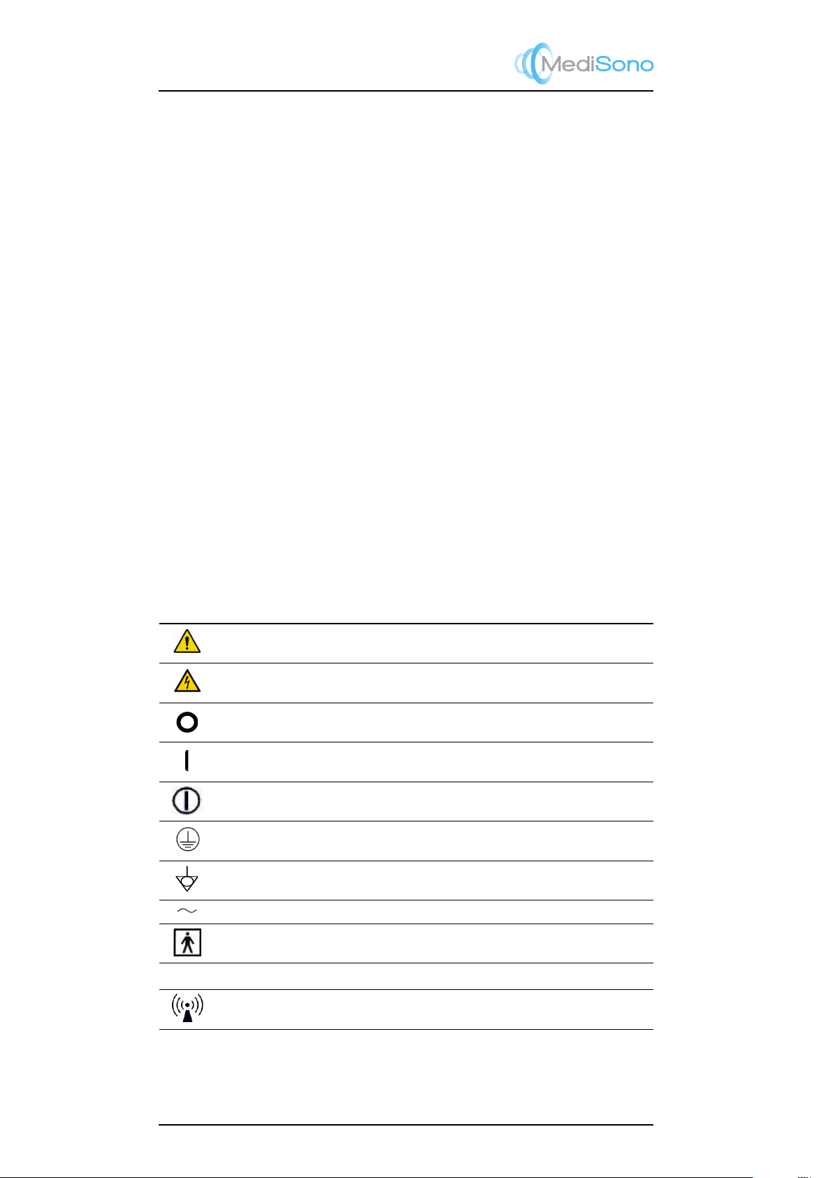
1.2 Description of Symbols and Signal Words Used
1.2.1 Symbols
The following symbols are utilized on the product or the label and package thereof.
Symbol Description
General warning sign
Warning: dangerous voltage
SSI-8000 Mobile Digital Color Doppler Ultrasound System
Service Manual
P/N: 4720-0018-01A
2-4
Off (Mains power switch OFF)
On (Mains power switch ON)
Protective earth/ground connection.
Potential equilibrium connection
AC
Off (Mains power switch OFF)
SSI-8000 Mobile Digital Color Doppler Ultrasound System
Service Manual
P/N: 4720-0018-01A
2-4
Off (Mains power switch OFF)
On (Mains power switch ON)
Protective earth/ground connection.
Potential equilibrium connection
AC
On (Mains power switch ON)
Icon for power switch button
SSI-8000 Mobile Digital Color Doppler Ultrasound System
Service Manual
P/N: 4720-0018-01A
2-4
Off (Mains power switch OFF)
On (Mains power switch ON)
Protective earth/ground connection.
Potential equilibrium connection
AC
Protective earth/ground connection.
SSI-8000 Mobile Digital Color Doppler Ultrasound System
Service Manual
P/N: 4720-0018-01A
2-4
Off (Mains power switch OFF)
On (Mains power switch ON)
Protective earth/ground connection.
Potential equilibrium connection
AC
Equipotentiality
SSI-8000 Mobile Digital Color Doppler Ultrasound System
Service Manual
P/N: 4720-0018-01A
2-4
Off (Mains power switch OFF)
On (Mains power switch ON)
Protective earth/ground connection.
Potential equilibrium connection
AC
AC
Type BF Applied Part
IPNNIP classification according to IEC 60529.
Non-ionization radiation: Ultrasound scanner transmits acoustic waves.
1-2
P11
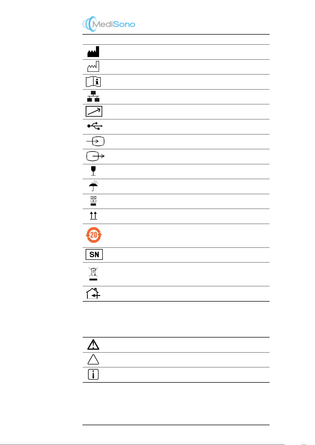
Portable Digital Color Doppler Ultrasound System
Manufacturer information according to EN 980.
Date of manufacture according to EN 980.
Consult operating instructions.
Network Port.
Control port of color video printer.
USB Port
Video input
Video Output
Fragile.
Keep dry.
Maximum stacking limit of packages. Maximum of two layers allowed!
Keep this way upward.
Indicates the presence of hazardous substance(s) above the maximum concentration value(s)
as set in SJ/T11364-2006. “20” indicates the number of years during which the hazardous
substance(s) will not leak or mutate so that the use of this product will not result in any severe
environmental pollution, bodily injury, or damage to any assets.
Unique number for the ultrasound system.
This symbol indicates that waste electrical and electronic equipment must not be disposed of
as unsorted municipal waste and must be collected separately. Please contact an authorized
representative of the manufacturer for information concerning the decommissioning of your
equipment.
Indoor use only.
1.2.2 Signal words
The following signal words are used throughout the user manual.
Symbol Description
Warning! Follow these instructions to avoid personal injury or system damage.
Caution! Follow these instructions to avoid system damage.
Note Follow these instructions to obtain additional helpful information.
1-3

P11
Portable Digital Color Doppler Ultrasound System
1.3 Messages
All the messages generated by this ultrasound system are self-explanatory. However, you
may encounter the following situations.
License renewal
When the validity of the license is less than 10 days, the message on the above right
will appear on the preparation mode (EXAM) screen. System function will not be
affected until the license is expired. When the license has been expired, the message
on the above left will appear when the user clicks an application mode icon. Please
contact our representative for license renewal.
Auto quit ultrasound scan
In order to protect the operator or the patient from accidentally receiving excessive
acoustic energy, the system automatically stops the real time scan (no on-screen
message will be provided) and returns the preparation mode if there has been no user
activity for 30 minutes. The user may resume the scan from the preparation mode.
No prerequisite action before another ultrasound scan is required.
1.4 Adverse Effects and Precautions
This ultrasound system, same as all other diagnostic ultrasound system in the market,
should be used only for clinically appropriate reasons, for the shortest period of time and
at power settings as low as reasonably achievable (ALARA). The American Institute of
Ultrasound in Medicine (AIUM) principle of As Low As Reasonably Achievable (ALARA)
is recommended during selection of the output of ultrasound power. Try not to aim probe
at the same spot in tissue for a long period of time unless it is necessary for diagnostic
purpose. This system, as a basic imaging system with the Doppler and Color Doppler
feature generates acoustic power that is below pre-enactment levels, which are generally
considered to be safe for the respective applications.
1.5 Biological Safety
This product, as with all diagnostic ultrasound equipment, should be used only for valid
reasons and should be used both for the shortest period of time and at the lowest power
settings necessary (
ALARA
- As Low As Reasonably Achievable) to produce diagnostically
acceptable images.
The AIUM offers the following guidelines:
Clinical Safety Quoted from AIUM
Approved March 26, 1997
Diagnostic ultrasound has been in use since the late 1950s. Given its
known benefits and recognized efficacy for medical diagnosis, including use
during human pregnancy, the American Institute of Ultrasound in Medicine
herein addresses the clinical safety of such use:
1-4

P11
Portable Digital Color Doppler Ultrasound System
There are no confirmed biological effects on patients or instrument oper-
ators caused by exposures from present diagnostic ultrasound instruments.
Although the possibility exists that such biological effects may be identified in
the future, current data indicate that the benefits to patients of the prudent use
of diagnostic ultrasound outweigh the risks, if any that may be present.
Heating:
Elevating tissue temperature during obstetrical examinations creates medical concerns. At
the embryo development stage, the rise in temperature and the length of time exposed to
heat combine to determine potential detrimental effects. Exercise CAUTION particularly
during Doppler/Color exams.
The Thermal Index (TI) provides a statistical estimate of the potential temperature elevation
(in centigrade) of tissue temperature. Three forms of TI are available: TIS, for soft tissue
exposures; TIB, for instances when bone lies near the beam focus; and TIC, for the heating
of bone situated close to the transducer.
Cavitation:
Cavitation may occur when sound passes through an area that contains a cavity, such as
a gas bubble or air pocket (in the lung or intestine, for example). During the process of
cavitation, the sound wave may cause the bubble to contract or resonate. This oscillation
may cause the bubbles to explode and damage the tissue. The Mechanical Index (MI) has
been created to help users accurately evaluate the likelihood of cavitation and the related
adverse effects.
1.6 Scanning Patients and Education
The Track-3 or IEC60601-2-37 output display standard allows users to share the respon-
sibility for the safe use of this ultrasound system. Follow these usage guidelines for safe
operation:
•
In order to maintain proper cleanliness of the transducers, always clean them between
patients.
•Always use a new disinfected sheath on all EV/ER probes during every exam.
•
Continuously move the probe, rather than staying in a single spot, to avoid elevated
temperatures in one part of the patient’s body.
•Move probe away from the patient when not actively scanning.
•
Understand the meaning of the TI, TIS, TIB, TIC, and MI output display, as well as
the relationship between these parameters and the thermal/cavitation bioeffect to the
tissue.
•
Expose the patient to only the very lowest practical transmit power levels for the
shortest possible time to achieve a satisfactory diagnosis (ALARA - As Low As
Reasonably Achievable).
1.6.1 Safe Scanning Guideline
1.
Ultrasound should only be used for medical diagnosis and only by trained medical
personnel.
2.
Diagnostic ultrasound procedures should be done only by personnel fully trained in
the use of the equipment, in the interpretation of the results and images, and in the
safe use of ultrasound (including education as to potential hazards).
1-5

P11
Portable Digital Color Doppler Ultrasound System
3.
Operators should understand the likely influence of the machine controls, the op-
erating mode (e.g. B-mode, color Doppler imaging or spectral Doppler) and probe
frequency on thermal and cavitation hazards.
4.
Select a low setting for each new patient. Output should only be increased during the
examination if penetration is still required to achieve a satisfactory result, and after
the Gain control has been moved to its maximum value.
5.
Maintain the shortest examination time necessary to produce a useful diagnostic
result.
6.
Do not hold the probe in a fixed position for any longer than is necessary. It should be
removed from the patient whenever there is no need for real-time imaging or spectral
Doppler acquisition. The freeze frame and Cine loop capabilities allow images to be
reviewed and discussed without exposing the patient to continuous scanning.
7.
Do not use endo-cavity probes if there is noticeable self heating of the probe when
operating in the air. Although applicable to any probe, take particular care during
trans-vaginal exams during the first eight weeks of gestation.
8.
Take particular care to reduce output and minimize exposure time of an embryo or
fetus when the temperature of the mother is already elevated.
9.
Take particular care to reduce the risk of thermal hazard during diagnostic ultrasound
when exposing: an embryo less than eight weeks after gestation; or the head, brain
or spine of any fetus or neonate.
10.
Operators should continually monitor the on-screen thermal index (TI) and mechanical
index (MI) values and use control settings that keep these settings as low as possible
while still achieving diagnostically useful results.
In obstetric examinations, TIS (soft tissue thermal index) should be monitored during
scans carried out in the first eight weeks after gestation, and TIB (bone thermal index)
thereafter. In applications where the probe is very close to bone (e.g. trans-cranial
applications), TIC (cranial thermal index) should be monitored.
MI>0.3 There is a possibility of minor damage to neonatal lung or
intestine. If such exposure is necessary, reduce the exposure time
as much as possible.
MI>0.7 There is a risk of cavitation if an ultrasound contrast agent
containing gas micro-spheres is being used. There is a theoretical
risk of cavitation without the presence of ultrasound contrast
agents. The risk increases with MI values above this threshold.
TI>0.7 The overall exposure time of an embryo or fetus should be
restricted in accordance with Table 1.1 below as a reference.
TI Maximum exposure time (minutes)
0.7 60
1.0 30
1.5 15
2.0 4
2.5 1
Table 1.1: Maximum recommended exposure times for an embryo or fetus
1-6

P11
Portable Digital Color Doppler Ultrasound System
11.
Non-diagnostic use of ultrasound equipment is not generally recommended. Ex-
amples of non-diagnostic uses of ultrasound equipment include repeated scans for
operator training, equipment demonstration using normal subjects, and the production
of souvenir pictures or videos of a fetus.
For equipment of which the safety indices are displayed over their full range of values,
the TI should always be less than 0.5 and the MI should always be less than 0.3.
Avoid frequent repeated exposure of any subject.
Scans in the first trimester of pregnancy should not be carried out for the sole purpose
of producing souvenir videos or photographs, nor should their production involve
increasing the exposure levels or extending the scan times beyond those needed for
clinical purposes.
12.
Diagnostic ultrasound has the potential for both false positive and false negative
results. Misdiagnosis is far more dangerous than any effect that might result from the
ultrasound exposure. Therefore, diagnostic ultrasound should be performed only by
those with sufficient training and education.
1.6.1.1 Temperature Display for Transducers Intended for Internal Use
For transducers intended for internal applications, for example the intracavitary or trans-
esophageal transducers, the transducer tip temperature is displayed on the screen. Refer
to
Figure 1.1
for the location of the temperature display. To protect the patient against the
harm of excessive temperature, the system automatically turns off the transducer when the
temperature of the transducer reaches a threshold temperature, which is adjustable and
has a maximum value of 43◦C.
Figure 1.1: Transducer tip temperature display
1.6.2 Understanding the MI/TI Display
Track-3 follows the Output Display Standard for systems which include fetal Doppler appli-
cations. The acoustic output will not be evaluated on an application-specific basis, but the
global maximum de-rated Ispta must be
≤
720 mW/cm2 and either the global maximum MI
must be
≤
1.9 or the global maximum de-rated Isppa must be
≤
190 W/cm2. An exception
1-7

P11
Portable Digital Color Doppler Ultrasound System
is for ophthalmic use, in which case the TI=max (TIS_as, TIC) is not to exceed 1.0; Ispta.3
≤
50mW/cm2, and MI
≤
0.23. Track-3 gives the user the freedom to increase the output
acoustic power for a specific exam, and still limit output acoustic power within the global
maximum de-rated Ispta ≤720 mW/cm2 under an Output Display Standard.
For any diagnostic ultrasonic systems, Track-3 provides an Output Indices Display Standard.
The diagnostic ultrasound systems and its operator’s manual contain the information
regarding an ALARA (As Low As Reasonably Achievable) education program for the clinical
end-user and the acoustic output indices, MI and TI.
The MI describes the likelihood of cavitation, and the TI offers the predicted maximum
temperature rise in tissue as a result of the diagnostic examination.
In general, a temperature increase of 2.5
◦C
must be present consistently at one spot for 2
hours to cause fetal abnormalities. Avoiding a local temperature rise above 1
◦C
should
ensure that no thermally induced biologic effect occurs.
When referring to the TI for potential thermal effect, a TI equal to 1 does not mean the
temperature will rise 1 degree C. It only means an increased potential for thermal effects can
be expected as the TI increases. A high index does not mean that bioeffects are occurring,
but only that the potential exists and there is no consideration in the TI for the scan duration,
so minimizing the overall scan time will reduce the potential for effects. These operator
control and display features shift the safety responsibility from the manufacturer to the user.
So it is very important to have the Ultrasound systems display the acoustic output indices
correctly and the education of the user to interpret the value appropriately.
RF: De-rating factor
In Situ intensity and pressure cannot currently be measured. Therefore, the acoustic power
measurement is normally done in the water tank, and when soft tissue replaces water along
the ultrasound path, a decrease in intensity is expected. The fractional reduction in intensity
caused by attenuation is DENOTED by the de-rating factor RF,
RF=(−.a·f·z)
Where a is the attenuation coefficient in dB cm-1 MHz-1, f is the transducer center
frequency, and z is the distance along the beam axis between the source and the
point of interest.
De-rating factor RF for the various distances and frequencies with attenuation coefficient
0.3dB cm-1 MHz-1 in homogeneous soft tissue is listed in the following table. An example
is if the user uses 7.5MHz frequency, the power will be attenuated by .0750 at 5cm, or
0.3x7.5x5=-11.25dB. The De-rated Intensity is also referred to as ’.3’ at the end (e.g.
Ispta.3).
Distance Frequency (MHz)
(cm) 1 3 5 7,5
1 0,9332 0,8128 0,7080 0,5957
2 0,8710 0,6607 0,5012 0,3548
3 0,8128 0,5370 0,3548 0,2113
4 0,7586 0,4365 0,2512 0,1259
5 0,7080 0,3548 0,1778 0,0750
6 0,6607 0,2884 0,1259 0,0447
7 0,6166 0,2344 0,0891 0,0266
8 0,5754 0,1903 0,0631 0,0158
I’=I*RF Where I’ is the intensity in soft tissue, I is the
time-averaged intensity measured in water.
Tissue Model
1-8

P11
Portable Digital Color Doppler Ultrasound System
Tissue temperature elevation depends on power, tissue type, beam width, and scanning
mode. Six models are developed to mimic possible clinical situations.
Thermal
Models
Composition Mode Specification Typ. app
1TIS Soft tissue Unscanned Large aperture
(>1cm)
Liver PW
2TIS Soft tissue Unscanned Small aperture
(<1cm)
Pencil probe
3TIS Soft tissue Scanned Evaluated at surface Breast color
4TIB Soft tissue and
bone
Scanned Soft tissue at surface Muscle color
5TIB Soft tissue and
bone
Unscanned Bone at focus Fetus head PW
6TIC Soft tissue and
bone
Unscanned / Scanned Bone at surface Trans cranial
Soft tissue
Describes low fat content tissue that does not contain calcifications or large gas-filled
spaces.
Scanned: (auto-scan)
Refers to the steering of successive burst through the field of view, e.g. B and color mode.
UnScanned
Emission of ultrasonic pulses occurs along a single line of sight and is unchanged until the
transducer is moved to a new position. For instance, the PW, CW and M mode.
TI
TI is defined as the ratio of the In Situ acoustic power (W.3) to the acoustic power required
to raise tissue temperature by 1oC (Wdeg),
T I =W./W deg
Three TIs corresponding to soft tissue (TIS) for abdominal; bone (TIB) for fetal and neonatal
cephalic; and cranial bone (TIC) for pediatric and adult cephalic, have been developed for
applications in different exams.
An estimate of the acoustic power in milliwatts necessary to produce a 1
◦C
temperature
elevation in soft tissue is:
W deg =/ f c
for model 1 to 4, where fc is the center frequency in MHz.
W deg = ·K·D
for model 5 and 6, where K (beam shape factor) is 1.0, D is the aperture diameter in
cm at the depth of interest
MI
Cavitation is more likely to occur at high pressures and low frequencies in pulse ultrasound
wave in the tissue, which contains the bubble or air pocket (for instance, the lung, intestine,
or scan with gas contrast agents). The threshold under optimum conditions of pulsed
ultrasound is predicted by the ratio of the peak pressure to the square root of the frequency.
MI =Pr0/pf c
Pr’ is the de-rated (0.3) peak rare-fractional pressure in Mpa at the point where PII is
the maximum, and fc is the center frequency in MHz. PII is the Pulse Intensity Integral
that the total energy per unit area carried by the wave during the time duration of the
pulse.
The peak rare-fractional pressure is measured in hydrophone maximum negative volt-
age normalized by the hydrophone calibration parameter.
1-9

P11
Portable Digital Color Doppler Ultrasound System
Display Guideline
For different operation modes, different indices must be displayed. However, only one index
needs to be shown at a time. Display is not required if maximum MI is less than 1.0 for
any setting of the operating mode, or if maximum TI is less than 1.0 for any setting of the
operating mode. For TI, if the TIS and TIC are both greater than 1.0, the scanners need not
be capable of displaying both indices simultaneously. If the index falls below 0.4, no display
is needed. The display increments are no greater than 0.2 for index value less than one
and no greater than 1.0 for index values greater than one (e.g. 0.4, 0.6, 0.8, 1, 2, 3).
Display and Report in Different Mode
For B-Scan Mode
Only display and report MI, and start from 0.4 if maximum MI > 1.0
For Color Mode
Only display and report TIS or TIB and start from 0.4 if maximum TI > 1.0
For Doppler Mode
Only display and report TIS or TIB and start from 0.4 if maximum TI > 1.0
Below is a simple guideline for the user when TI exceeds one limit exposure time to 4(6-TI)
minutes based on the National Council on Radiation Protection. Exposure Criteria for
Medical Diagnostic Ultrasound: I. Criteria Based on Thermal Mechanisms. Report No.113
1992:
Operator Control Features
The user should be aware that certain operator controls may affect the acoustic output. It is
recommended to use the default (or lowest) output power setting and compensate using
Gain control to acquire an image. Other than the output power setting in the soft-menu,
which has the most direct impact on the power; the PRF, image sector size, frame rate,
depth, and focal position also slightly affect the output power. The default setting is normally
around 70% of the allowable power depending on the exam icon.
1.7 Environmental Requirements
The environmental requirements for using the ultrasound system are listed below.
Operation
Temperature: 10◦C∼40◦C
Relative Humidity: 30%∼75%, no condensation
Atmospheric Pressure: 700∼1060hPa
Transport and Storage
Temperature: -20◦C∼55◦C
Relative Humidity: 20% ∼90 %, no condensation
Atmospheric Pressure: 700∼1060hPa
Strong radiation sources or powerful electromagnetic waves (e.g. electromagnetic waves
from radio broadcasting) may result in image ghosting or noise. The system should be
isolated from such radiation sources or electromagnetic waves.
1.8 Electrical Requirements
Power Supply Requirements: 110-240V∼, 2.7–1.2A, 50/60Hz
1-10

P11
Portable Digital Color Doppler Ultrasound System
Ultrasound system input / AC adapter output: 17.5V, 10A
Main unit voltage
Maintain a fluctuation range of less than ±10% or the system may be damaged.
Grounding
Before connecting the power cable, connect the attached ground protection cable to a
specialized grounding device.
Note
•
Please ensure that the power requirements are satisfied. Only use
power lines that meet the system guidelines—failure to follow these
procedures may result in system damage.
• Voltage level may vary in different geographic locations.
•
Use only the power button on the side panel to turn on or off the unit.
Mains power switch on the rear panel should be always ON unless
prior to transport or maintenance or service of the equipment.
Caution for using AC adapter:
• Use the AC adapter approved by MediSono only.
• AC adapter can get very hot if being used in poorly ventilated area. Main-
tain good ventilation for heat dissipation. Do not put any items on the AC
adapter or the power cable.
• Make sure that the power cable is not entangled and avoid being tripped
over by the cable.
• Do not use the adapter without removing its carrying case.
• To ensure proper grounding, connect the AC adapter to a receptacle/outlet
marked with “hospital grade”.
Caution for using battery:
• To assure the best performance of the system, we recommend to replace
the battery pack every three years.
• This battery is designed to be an integral part of the ultrasound system. At-
tempting do-it-yourself removal of the battery not only voids the warranty but
also violates the regulations, and is discouraged by IEC 60601-1.
• Do not short the conductive parts of the battery.
• The temperature of the battery can be high right after discharging com-
pletes. To protect it from overheat damage, it will not be charged imme-
diately after being connected to an AC supply.
• During long time storage of the battery, a discharge-charge cycle should be
performed in every 3 to 6 months.
• Do not discard the battery in fire.
• Do not remove the battery pack from the system.
• Do not put foreign metal or other conductive parts inside the system to avoid
electrical short.
• Protect the battery from rain and do not immerse the battery in water.
• Do not place the system at unstable position and use the system.
• Do not heat or burn the battery.
• Do not use the system near any source which produces significant amount
of heat, such as fire and heater.
• Do not charge or discharge the battery in direct sunlight.
• Do not destroy or disassemble the battery; Do not solder the battery.
• This battery pack should only be used with the ultrasound system which it has
been designed for.
• Do not use the battery in strong electric field.
For more information about the AC adapter and the battery, read Section 3.2.
1-11

P11
Portable Digital Color Doppler Ultrasound System
1.9 Electrical Safety
Caution!
Only trained health-care professionals should operate this system.
This equipment complies with the following standards:
•The equipment conforms with the following regulations for electrical safety,
–
EN 60601-1 (IEC 60601-1), Medical electrical equipment Part 1: General
requirements for basic safety and essential performance, Class I, BF, continuous
operation.
–
EN 60601-2-37:2008 (IEC 60601-2-37:2007), Medical Electrical Equipment Part
2-37: Particular Requirements for the Basic Safety and Essential Performance
of Ultrasonic Medical Diagnostic and Monitoring Equipment.
•The equipment conforms with the following EMC/EMI standards:
–
EN 60601-2-37:2008 (IEC 60601-2-37:2007) and EN 60601-1-2:2007 (IEC
60601-1-2: 2007), Class A
•Degrees of protection against harmful liquid:
For the main
system:
IPX0
For the transducer:
IPX7, from the acoustic window to the junction line (
Fig-
ure 13.1
); and IPX1 for other parts that may contact
with the patient, excluding the transducer connector.
For maximum safety, adhere to these guidelines:
• Proper grounding of the system is critical to avoid electrical shock. For protec-
tion, ground the system with a three-conductor cable, and plug the system
into a hospital-grade receptacle or outlet.
• Do not remove or entangle the grounding wire.
• Do not remove the protective covers of the system. These covers protect
users from hazardous voltages. Only authorized service technicians can make
replacements of the parts inside the system.
• Never use this system while inflammable gas is present!
• Devices must be powered from the receptacles marked “hospital grade” or
“hospital only” before being connected to the system directly. In case where
“hospital grade” receptacles are not available, use isolation transformers in-
stead.
• Operators and patient must not contact any exposed metal terminals of the
plugs.
• Duration of continuous physical contact with any applied parts of this ultra-
sound system must not exceed 4 hours.
1-12

P11
Portable Digital Color Doppler Ultrasound System
1.10 Cautions for Using Accessories
•
Any accessories, provided by other manufacturers other than MediSono, to be
connected either electrically or mechanically to this ultrasound system must comply
with the specified IEC standards (IEC 60950 Information Technology Equipment -
Safety and IEC 60601-1 Medical electrical equipment Part 1: General requirements
for basic safety and essential performance.)
•
For cleaning, disinfection and sterilization of accessories, please follow the instruc-
tions provided by the manufacturers.
•
Installation and service of accessories shall be performed according to the require-
ments of the manufacturers.
•
Disposal of the accessories at the end of the product life shall follow the guidance of
the manufacturers.
•
The accessories provided with the ultrasound system, e.g. the foot switch and the
printer, are safe to operate in patient environment. Other accessories or devices not
listed in the list of supported accessories must not be used. You may contact us for
the updated version of the list.
1.10.1 Foot Switch
The foot switch paddle must not be used in the operating room.
1.10.2 Optional Printers
Ensure that the outlets used by the printer have the protective grounding conductor before
connecting the printer to the ultrasound system.
Consult MediSono for guidance on installation and service of the printers.
1.10.3 Transducer Maintenance
The transducers/probes provided with the system are durable and have reliable performance.
These precision instruments should be inspected daily and handled with care. Please
observe the following PRECAUTIONS:
• Do not drop the transducer on the hard surface. This can damage the trans-
ducer elements and compromise the electrical safety of the transducer.
• Avoid kinking or pinching the transducer cable.
• Use only approved ultrasound coupling gels.
• Follow the instructions for cleaning and disinfecting the probes.
Disinfecting Surface Transducers
• Disconnect the transducer from the system.
• Wipe all surfaces with isopropyl alcohol solution and air dry.
• Clean all surfaces of the probe and cable with soft cloth.
• Allow the transducer to air dry prior to storage or further use.
The following statement from AIUM outlines instructions for cleaning the intracavitary
transducer:
1-13

P11
Portable Digital Color Doppler Ultrasound System
Guidelines for Cleaning and Preparing Endocavitary Ultrasound
Transducers between Patients from AIUM
Approved June 4, 2003
The purpose of this document is to provide guidance regarding the clean-
ing and disinfection of transvaginal and transrectal ultrasound probes.
All sterilization/disinfection represents a statistical reduction in the number
of microbes present on a surface. Meticulous cleaning of the instrument is the
essential key to an initial reduction of the microbial/organic load by at least
99%. This cleaning is followed by a disinfecting procedure to ensure a high
degree of protection from infectious disease transmission, even if a disposable
barrier covers the instrument during use.
Medical instruments fall into different categories with respect to potential
for infection transmission. The most critical level of instruments are those
that are intended to penetrate skin or mucous membranes. These require
sterilization. Less critical instruments (often called “semi-critical” instruments)
that simply come into contact with mucous membranes such as fiber optic
endoscopes require high-level disinfection rather than sterilization.
Although endocavitary ultrasound probes might be considered even less
critical instruments because they are routinely protected by single use dispos-
able probe covers, leakage rates of 0.9% - 2% for condoms and 8%-81% for
commercial probe covers have been observed in recent studies. For maxi-
mum safety, one should therefore perform high-level disinfection of the probe
between each use and use a probe cover or condom as an aid in keeping the
probe clean.
There are four generally recognized categories of disinfection and steril-
ization.
Sterilization is the complete elimination of all forms or microbial life
including spores and viruses.
Disinfection, the selective removal of microbial life, is divided into
three classes:
•High-Level Disinfection -Destruction/removal of all microorganisms ex-
cept bacterial spores.
•Mid-Level Disinfection - Inactivation of Mycobacterium Tuberculosis, bac-
teria, most viruses, fungi, and some bacterial spores.
•Low-Level Disinfection - Destruction of most bacteria, some viruses and
some fungi. Low-level disinfection will not necessarily inactivate My-
cobacterium Tuberculosis or bacterial spores.
The following specific recommendations are made for the use of intracavitary ultrasound
transducers.
Users should also review the Centers for Disease Control and Prevention document on
sterilization and disinfection of medical devices to be certain that their procedures conform
to the CDC principles for disinfection of patient care equipment.
1. CLEANING
•
After removing the probe cover, use flowing water to remove any residual from the
probe.
•
Use a damp gauze pad or other soft cloth and a small amount of mild non-abrasive
soap water to thoroughly clean the transducer.
•
Use a soft bristle brush for cleaning if the residue has dried onto the probe surface.
Rinse the transducer thoroughly with running water, and allow to air dry or dry with a
soft cloth.
1-14
Table of contents
Other MediSono Medical Equipment manuals


Popular Medical Equipment manuals by other brands


Getinge
Getinge Arjohuntleigh Nimbus 3 Professional Instructions for use

Mettler Electronics
Mettler Electronics Sonicator 730 Maintenance manual

Pressalit Care
Pressalit Care R1100 Mounting instruction

Denas MS
Denas MS DENAS-T operating manual

bort medical
bort medical ActiveColor quick guide

AccuVein
AccuVein AV400 user manual


