MediSono P12 EXP User manual

User Manual
P12 EXP
Ultrasound System
Version 1.4

About This Manual
P/N: 4710.01146X01
4710.00449A04
Product Model: P12EXP
Statement
The manufacturer owns the intellectual property rights to this manual, and also maintains the
contents of this manual as confidential information. This manual is a reference to operation,
maintenance or cleaning for the product and does not convey any license under the patent rights of
the manufacturer, nor the rights of others.
This manual contains the information protected by copyrights or patents. Reproduction, amendment
or translation of this manual in any manner whatsoever without the written permission of the
manufacturer is strictly forbidden.
All information contained in this manual is believed to be correct. The manufacturer shall not be
liable for errors contained herein or for incidental or consequential damages in connection with the
furnishing, performance or use of this manual. The manufacturer does not assume any liability
arising out of any infringements of patents or other rights of third parties.
This manual is subject to change without prior notice and legal obligation.
Manufacturer’s Responsibility
The manufacturer is responsible for the effects on safety, reliability and performance of this product,
only if:
●all installation operations, expansions, changes, modifications and repairs of this product are
conducted by the manufacturer authorized personnel;
●the use or application of the product or the use of parts or accessories is approved by the
manufacturer.
●the electrical installation of the relevant room complies with the applicable national and local
requirements; and
●the product is used in accordance with the instructions for use.
Documentation
The manufacturer provides the documentation consisted of various manuals:
●Basic User Manual (this manual) describes the basic functions and operating procedures of the
system.
●Advanced User Manual provides information about the measurements and calculations available
in each mode.
●Compact Disc (CD) provides the acoustic output data related to the system.
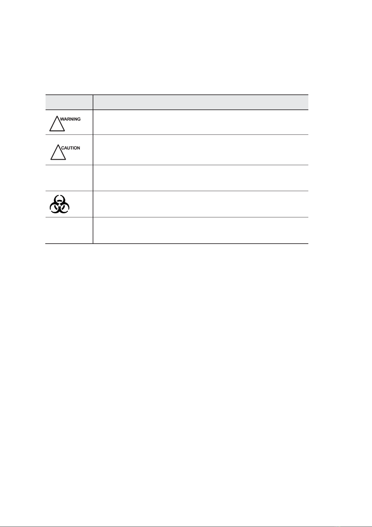
Signal words in this manual are defined as follows. Please understand their meanings clearly before
reading this manual.
Signal Word
Meaning
!
Indicates a potentially hazardous situation which, if not avoided, could result
in death or serious injury.
Indicates a potentially hazardous situation which, if not avoided, may result in
malfunction or damage of the system.
NOTE
Indicates precautions or recommendations that should be used in operating the
system.
Indicates a potentially biological hazardous situation which, if not avoided,
may result in disease transmission.
Boldfaced
Word
Indicates keys and controls located on the control panel, or on-screen objects
such as menu items or keys.
Contact Information
Manufacturer: MEDISONO
Address: 3511 Silverside RD. Wilmington, DE 19810, United States
INFO@MEDISONO.COM


I
Contents
Chapter 1 Safety
1.1 Intended Use ..........................................................................................................................2
1.2 Safety Precautions..................................................................................................................2
1.2.1 Electrical Safety...........................................................................................................2
1.2.2 Mechanical Safety.......................................................................................................4
1.2.3 Accessories Caring ......................................................................................................4
1.2.4 Biohazard Considerations............................................................................................5
1.3 Acoustic Power Principle.......................................................................................................5
1.3.1 Biological Safety.........................................................................................................5
1.3.2 ALARA .......................................................................................................................5
1.3.3 Mechanical and Thermal Indices.................................................................................6
1.3.4 Transducer Surface Temperature Limits .....................................................................7
1.3.5 Imaging Functions that Change Acoustic Output........................................................7
1.4 Safety Symbols ......................................................................................................................7
Chapter 2 System
Overview 11
2.1 System Configuration ..........................................................................................................12
2.2 Physical Specifications.........................................................................................................12
2.3 System Components.............................................................................................................13
2.3.1 Peripheral Device Panel.............................................................................................15
2.3.2 Control Panel.............................................................................................................16
2.3.3 Key Panel...................................................................................................................19
2.3.4 Basic Screen .............................................................................................................. 21
Chapter 3 Preparing the System
23
3.1 SystemAssembly.................................................................................................................24
3.2 System Moving/Positioning.................................................................................................25
3.3 Connecting and Powering on the System.............................................................................26
3.3.1 Using the Mains Supply ............................................................................................26
3.3.2 Using the Battery.......................................................................................................26
3.3.3 Indicators...................................................................................................................27
3.4 Powering On/Off the System...............................................................................................28
3.5 Adjusting the System ..........................................................................................................29

II
3.5.1 Adjusting the Monitor Arm ....................................................................................... 29
3.5.2 Adjusting the Display Monitor.................................................................................. 30
3.6 Connecting the Probe........................................................................................................... 31
3.7 Connecting the Peripheral Device ....................................................................................... 32
3.7.1 Connecting the Footswitch........................................................................................ 32
3.7.2 Connecting the Video Printer .................................................................................... 32
3.7.3 Connecting the Network Printer................................................................................ 33
3.7.4 Connecting the USB Printer...................................................................................... 34
Chapter 4 Customizing Your System
35
4.1 General System Settings...................................................................................................... 36
4.1.1 General Settings ........................................................................................................ 36
4.1.2 Display Settings......................................................................................................... 39
4.1.3 Storage Settings......................................................................................................... 40
4.1.4 Defined-Key Settings................................................................................................ 41
4.2 Peripheral Device Settings................................................................................................... 42
4.3 Measurement Settings.......................................................................................................... 44
4.3.1 General Measurement Settings.................................................................................. 44
4.3.2 Application Settings .................................................................................................. 46
4.3.3 List Settings............................................................................................................... 49
4.4 Report Settings..................................................................................................................... 50
4.5 Configuring DICOM............................................................................................................ 51
4.5.1 Storage Service Settings............................................................................................ 51
4.5.2 Commitment Settings................................................................................................ 53
4.5.3 DICOM Worklist Settings......................................................................................... 54
4.5.4 MPPS Settings........................................................................................................... 56
4.5.5 Print Service Settings ................................................................................................ 57
4.6 Defining System Defaults.................................................................................................... 59
4.7 Viewing System Information............................................................................................... 61
Chapter 5 Preparing for an Exam
63
5.1 Acquiring Patient Information ............................................................................................. 64
5.1.1 Beginning a New Patient........................................................................................... 64
5.1.2 Retrieving Archived Information .............................................................................. 66
5.1.3 Using DICOM Worklist.................................................................................................67
5.2 Pausing/Resuming an Exam ................................................................................................ 67
5.3 Completing/Discontinuing an Exam....................................................................................68

I
I
I
5.3.1 Completing an Exam.................................................................................................68
5.3.2 Discontinuing an Exam .............................................................................................68
Chapter 6 Acquiring Images
69
6.1 Selecting a Probe and an Exam Type............................................................................................70
6.2 Acquiring B-Mode Images...................................................................................................72
6.2.1 Entering B Mode .......................................................................................................72
6.2.2 Optimizing B-Mode Images......................................................................................73
6.2.2.1 Gain...............................................................................................................73
6.2.2.2 TGC ..............................................................................................................73
6.2.2.3 LGC ..............................................................................................................73
6.2.2.4 Focal Position/Number/Span ........................................................................ 74
6.2.2.5 Depth.............................................................................................................74
6.2.2.6 Frequency......................................................................................................74
6.2.2.7 Chroma .........................................................................................................74
6.2.2.8 Compound Imaging ......................................................................................75
6.2.2.9 Line Density..................................................................................................75
6.2.2.10 Persistence ..................................................................................................75
6.2.2.11 Dynamic Range...........................................................................................75
6.2.2.12 Grayscale Curve..........................................................................................76
6.2.2.13 Adaptive Image Fusion ...............................................................................76
6.2.2.14 Sector Position/Width/Angle ...................................................................... 76
6.2.2.15 Power..........................................................................................................76
6.2.2.16 TissueAcoustic Characteristics...................................................................77
6.2.2.17 Image Rotation............................................................................................77
6.2.2.18 μScan ..........................................................................................................77
6.2.2.19 Trapezoidal Imaging...................................................................................77
6.2.2.20 Steer............................................................................................................78
6.3 Acquiring Color Flow Images..............................................................................................78
6.3.1 CFM Mode ................................................................................................................ 78
6.3.2 PDI Mode ..................................................................................................................79
6.3.3 TDI Mode..................................................................................................................80
6.3.4 Optimizing CFM/PDI/TDI Mode Images..................................................................81
6.3.4.1 Gain...............................................................................................................81
6.3.4.2 Frequency..................................................................................................... 81
6.3.4.3 Wall Filter..................................................................................................... 81
6.3.4.4 Pulse Repetition Frequency.......................................................................... 81

IV
6.3.4.5 Line Density ................................................................................................. 81
6.3.4.6 Baseline ........................................................................................................ 82
6.3.4.7 Color Map..................................................................................................... 82
6.3.4.8 Persistence.................................................................................................... 82
6.3.4.9 Sector Position/Width/Angle........................................................................ 83
6.3.4.10 Power.......................................................................................................... 83
6.3.4.11 B Reject ...................................................................................................... 83
6.3.4.12 Steer............................................................................................................ 83
6.3.4.13 Flow Invert ................................................................................................. 84
6.4 Acquiring M-Mode Images................................................................................................. 84
6.4.1 M Mode..................................................................................................................... 84
6.4.2 Anatomical M-Mode ................................................................................................. 86
6.4.3 Optimizing M-Mode Images..................................................................................... 86
6.4.3.1 Gain .............................................................................................................. 87
6.4.3.2 M Process ..................................................................................................... 87
6.4.3.3 Sweep Speed................................................................................................. 87
6.4.3.4 Chroma ......................................................................................................... 87
6.4.3.5 Display Format ............................................................................................. 87
6.4.3.6 Power............................................................................................................ 88
6.4.3.7 Video Invert.................................................................................................. 88
6.5 Acquiring Spectral Doppler Images..................................................................................... 88
6.5.1 PW Mode................................................................................................................... 88
6.5.2 CW Mode.................................................................................................................. 91
6.5.3 Optimizing Spectral Doppler Images........................................................................ 93
6.5.3.1 Gain .............................................................................................................. 93
6.5.3.2 Pulse Repetition Frequency.......................................................................... 93
6.5.3.3 High Pulse Repetition Frequency................................................................. 94
6.5.3.4 Baseline ........................................................................................................ 94
6.5.3.5 Wall Filter..................................................................................................... 94
6.5.3.6 Frequency..................................................................................................... 95
6.5.3.7 Sweep Speed................................................................................................. 95
6.5.3.8 Power............................................................................................................95
6.5.3.9 Chroma .........................................................................................................95
6.5.3.10 Dynamic Range........................................................................................... 95
6.5.3.11 Display Format............................................................................................96
6.5.3.12 Flow Invert..................................................................................................96

V
6.5.3.13 Video Invert ................................................................................................96
6.5.3.14 Angle Correction.........................................................................................96
6.5.3.15 Simult..........................................................................................................97
6.6 Acquiring Triplex-Mode Images..........................................................................................97
6.6.1 B+CFM/TDI +M....................................................................................................... 97
6.6.2 B+CFM/DPI/TDI +PW............................................................................................. 98
6.6.3 B+CFM/DPI+CW.................................................................................................... 100
Chapter 7 Elastography Imaging
101
7.1 Acquiring Elastography Images......................................................................................... 102
7.2 Optimizing Elastography Images....................................................................................... 103
7.2.1 Strain Map............................................................................................................... 103
7.2.2 Strain Process ..........................................................................................................104
7.2.3 Transparency ...........................................................................................................104
7.2.4 Contrast ...................................................................................................................104
7.2.5 Persistence...............................................................................................................104
7.2.6 Frequency................................................................................................................104
7.3 Working with Elastography Images ................................................................................... 105
Chapter 8 3D Imaging
107
8.1 Acquiring 3D Images ......................................................................................................... 108
8.2 Working with 3D Images ................................................................................................... 110
8.2.1 Adjusting ROI.......................................................................................................... 110
8.2.2 Setting Display Format.............................................................................................111
8.2.3 Setting Render Mode................................................................................................111
8.2.4 Cropping Reviews by the Trace ...................................................................................111
8.2.5 Moving/Rotating/Magnifying Images..................................................................... 112
8.2.6 Optimizing 3D Image.............................................................................................. 113
8.2.7 Observing Reviews by the Slice.............................................................................. 114
8.2.8 Setting the Scan Mode............................................................................................. 115
8.2.9 Adjusting ZAngle/ZScale........................................................................................ 115
8.2.10 Restoring the Image ...............................................................................................115
8.2.11 User Mode..............................................................................................................115
8.2.12 Measurement..........................................................................................................116
Chapter 9 4D Imaging
117
9.1 Acquiring 4D Images..........................................................................................................118
9.1.1 Entering the Real-Time 4D Imaging........................................................................118

VI
9.1.2 Acquiring Dynamic 3D Image .................................................................................119
9.2 Working with 4D Images................................................................................................... 120
Chapter 10 Working with Images
121
10.1 Imaging Features ............................................................................................................. 122
10.1.1 Imaging Reverse.................................................................................................... 122
10.1.2 Split Display.......................................................................................................... 122
10.1.3 m-Tuning............................................................................................................... 123
10.1.4 Harmonic Imaging................................................................................................. 124
10.1.5 Panoramic Imaging ............................................................................................... 124
10.2 Magnifying an Image....................................................................................................... 127
10.3 Freezing an Image............................................................................................................ 127
10.4 Using Cine....................................................................................................................... 127
10.4.1 Reviewing Cine..................................................................................................... 127
10.4.2 Cutting Cine.......................................................................................................... 128
10.5 Annotations and Body Marks........................................................................................... 128
10.5.1 Annotating an Image with Typed Words.......................................................................128
10.5.2 Annotating an Image with Arrows......................................................................... 129
10.5.3 Body Mark ............................................................................................................ 129
10.5.4 Deleting Annotations and Body Marks ................................................................. 130
10.6 Using ECG....................................................................................................................... 130
10.6.1 Basic Procedures of ECG Operation..................................................................... 131
10.6.2 Optimizing Parameters.......................................................................................... 131
10.6.3 Reviewing ECG..................................................................................................... 132
Chapter 11 Managing Images/Data
133
11.1 Storing an Image.............................................................................................................. 134
11.1.1 Storing 2D Image .................................................................................................. 134
11.1.2 Storing 3D/4D Image ............................................................................................ 134
11.2 Viewing an Image.............................................................................................................134
11.2.1 Viewing the Current Image....................................................................................134
11.2.2 Retrieving an Image...............................................................................................135
11.3 Sharing Data.....................................................................................................................136
11.4 Backing up Data...............................................................................................................136
11.4.1 Backing up Data to the USB drive.........................................................................136
11.4.2 Backing up Data to DVD.......................................................................................136
11.5 Importing Data to the System...........................................................................................137

V
I
I
Chapter 12 Working with
DICOM
139
12.1 Verifying Connectivity .....................................................................................................140
12.2 DICOM Storage ...............................................................................................................140
12.3 DICOM Print....................................................................................................................140
12.4 DICOM Worklist...................................................................................................................141
12.5 MPPS................................................................................................................................142
12.6 Storage Commitment........................................................................................................144
12.7 DICOM Queue.................................................................................................................144
Chapter 13 Probes and
Biopsy
145
13.1 Probe ................................................................................................................................146
13.1.1 Available Probes....................................................................................................146
13.1.2 Probe Usage...........................................................................................................147
13.1.3 Cleaning the Probe.................................................................................................148
13.1.4 Disinfecting and Sterilizing the Probe...................................................................149
13.1.5 Disinfecting and Sterilizing the Probe Cable.........................................................152
13.1.6 Storage and Transportation....................................................................................153
13.2 Biopsy ..............................................................................................................................153
13.2.1 Available Biopsy Brackets.....................................................................................154
13.2.2 Assembling the Biopsy Bracket.............................................................................154
13.2.3 Preparing for a Biopsy...........................................................................................157
13.2.4 Verifying the Biopsy Bracket.................................................................................157
13.2.5 Performing a Biopsy..............................................................................................157
13.2.6 Cleaning the Biopsy Bracket .................................................................................159
13.2.7 Sterilizing the Biopsy Bracket ...............................................................................159
13.2.8 Storage...................................................................................................................160
Chapter 14 System Maintenance
161
14.1 Cleaning the System ........................................................................................................ 162
14.2 Maintenance Checks........................................................................................................ 163
14.3 Troubleshooting............................................................................................................... 164
14.4 Replacing the Fuse........................................................................................................... 164
14.5 Equipment Disposal......................................................................................................... 165
14.6 Customer Service............................................................................................................. 165

VI
II
Appendix A
Specifications167
Appendix B EMC Guidance and Manufacturer’s Declaration
169
B.1 Electromagnetic Emissions............................................................................................... 169
B.2 Electromagnetic Immunity................................................................................................ 170
B.3 Recommended Separation Distances between Portable and Mobile RF Communications
Equipment and the Equipment.................................................................................................. 172
Appendix C In Situ, Derated, and Water Value Intensities 173
Appendix D Acoustic Output Data
175

I
X
Chapter 1 Safety
This chapter describes the important information for operating this ultrasound system. To ensure the
safety of both operator and patient, please read the relevant details in this chapter carefully before
using this system.
Youshould be thoroughly familiar with the precautions provided in this manual. Otherwise, the man-
ufacturer is not responsible for the effects on safety, reliability and performance of the ultrasound
system.

1 Safety
Basic User Manual
2
1
�
1 Intended Use
The ultrasound system is a general-purpose ultrasonic imaging instrument intended for use by a
qualified physician for evaluation of Fetal, Abdominal, Pediatric, Small Organ (breast, testes,
thyroid), Cephalic (neonatal and adult), Trans-rectal, Trans-vaginal, Peripheral Vascular, Musculo-
skeletal (Conventional and Superficial), Cardiac (pediatric and adult), OB/Gyn andUrology.
The ultrasound system also provides the measurement and calculation packages used for clinical
diagnosis purposes. For details, please refer to Advanced User Manual.
Contraindication: The ultrasound system is not intended for ophthalmic use or any use causing the
acoustic beam to pass through the eye.
!
Precautions must be considered in the use of any application. Otherwise, it may result
in system damage or serious injury.
1
�
2 Safety Precautions
Read and understand all precautions in this manual before attempting to use the ultrasound system.
Keep this manual with the ultrasound system at all times. Periodically review the procedures for
operation and safety precautions.
1
�
2
�
1 Electrical Safety
!
●Only qualified physicians or sonographers can perform ultrasound scanning on
human subjects for medical diagnostic reasons.
●Any unauthorized personnel should not tamper with the main unit of thissystem.
●Do not operate this system in an atmosphere containing flammable gases or
liquids such as anesthetic gases, hydrogen, and ethanol, because there is danger of
explosion.
●If this system is transported to the operating environment with a great temperature
change, leave it for about 4 hours before powering on it. Ensure temperature and
humidity inside and around this system are equivalent before the operation.
●Do not use this system around the strong electric field, the strong electromagnetic
field and the devices which generate radio waves, such as the radio, cellular
telephones, transceivers. Using the system in the improper environment may result
in malfunction or damage.
●Do not use this system at the same time with other equipment such as electric knife,
high-frequency therapy equipment and defibrillator. Otherwise, there is a danger of
electric shock.
●Connect the earth conductor only before powering on the system. Disconnect the
grounding cable only after powering off the system. Otherwise, there is a danger of
electric shock.
●Ensure the potential-equalization lead wire is connected before inserting the
equipment power plug.

1 Safety
Basic User Manual
3
●The AC power connector plug for the ultrasound system is a three-prong grounded
plug and should never be adapted to any two-prong outlet or by using an adapter.
The AC power connector plug should be plugged into a hospital-grade poweroutlet.
●Select the qualified multi-socket outlet with protective grounding, and ensure its
maximum output power exceed the required one of this system.
●The multi-socket outlet can only be used to provide power to the recommended
peripheral devices of this system.
●Do not place the multi-socket outlet on the floor.
●Do not connect other devices to the multi-socket outlet; otherwise, the rated output
power may be exceeded and failure may be resulted.
●The video printer should be connected to the specific interface using the cable
provided by the manufacturer; Otherwise, there is a danger of electric shock.
●Accessory equipment connected to the analog and digital interfaces must be certified
according to the respective EN/IEC standards (for example, EN/IEC 60950 for data
processing equipment and EN/IEC 60601-1 for medical equipment). Furthermore,
all configurations shall comply with the system standards EN/IEC 60601-1.
●In the environment that patient is 1.8 meters (6 feet) around, connect peripherals
to the auxiliary power outlet which is capable of isolation protection, or power the
peripherals by auxiliary output cable or isolation transformer complied with EN/IEC
60601-1 or the power input of the same safety level.
●Parts of non-medical electrical equipment in the patient environment that, after
removal of covers, connectors, etc., without the use of a tool, may be contacted
during the routine maintenance, calibration, etc. You should not touch the referred
parts and the patient simultaneously.
●Do not use the transducers other than those provided by the manufacturer.
Otherwise, the ultrasound system cannot be performed, and an accident such as a
fire may result in the worst case.
●Only the peripherals and accessories provided or recommended by the manufacturer
can be used. Using other devices or accessories may degrade the system
performance and even cause an electrical shock.
●Do not pour any fluid onto the ultrasound system surfaces, as fluid seepage into
the electrical circuitry may cause excessive leakage current or system failure. If
carelessly pour any water onto the system, immediately stop using the ultrasound
system and contact Service Representative immediately.

1 Safety
Basic User Manual
4
1
�
2
�
2 Mechanical Safety
!
●Do not place other objects on top of the control panel. Do not sit on the control
panel or other part of the ultrasound system.
●Do not knock or shake the ultrasound system.
●Ensure that the casters are intact and can rotate well before moving thesystem.
●Always use the handle to move the ultrasound system. Ensure the foot brakes are
released and all cables are away from the casters when moving the system.
●Ensure the footswitch is disconnected and the system is powered off before moving
the system.
●Casters of the system could cause injury if they rolls over feet or into shins. Take
cautions when moving the ultrasound system going up or down ramps.
●To avoid possible personnel injury and system damage, move the system slowly and
carefully, and lock foot brakes after arrival.
1
�
2
�
3 Accessories Caring
!
●Do not use the footswitch in the operating room.
●Disconnect the probe from the system after freezing an image or powering off the
system. Otherwise, the system or the probe could be damaged.
●Freeze the image at any time if you do not operate the ultrasound system for a long
period.
●Use the transducer carefully. If any part of the transducer surface is scratched,
immediately stop using the transducer. Otherwise, there is a danger of electric
shock.
●After disinfecting the accessories, chemicals must be washed out or gases must be
discharged thoroughly from the accessories. Remaining residual chemicals or gases
could not only result in damage to the accessories but also can be harmful to human
bodies.
●Only the trained physicians or sonographers under ultrasound guidance can
handle the biopsy needle guides. During the operation, the operator must observe
proper needle insertion sequencing with the needle guide in order to avoid undue
discomforts, unnecessary risks or injuries to the patient.
●Contact with natural rubber latex may cause a severe anaphylactic reaction in
persons sensitive to the natural latex protein. The operator and patients must avoid
contact with these items. Refer to package labeling to determine latex content and
FDA’s March 29, 1991 Medical Alert on latex products.
●Use the legally marketed coupling gel in accordance with the relevant local
regulations. Read and understand all precautions in the relevant manual of the
coupling gel before using it.
●Prepare, use, store and dispose the cleaner, disinfectant and sterilant according to
the instructions provided by manufacturers.

1 Safety
Basic User Manual
5
1
�
2
�
4 Biohazard Considerations
●To minimize the risk of cross-contamination or infectious diseases when performing
the biopsy, the operator should wear disposable gloves, protective clothing or
protective goggle if it is needed. Follow the working regulations strictly in case the
skin contacts the samples.
●Some disinfectants are acid or alkaline, the operator should take cautions in
preventing hands or clothing from being directly contact with them. Wash hands or
eyes immediately if they are contaminated by the disinfectants.
●Dispose of the cleaners, disinfectants or discard solutions in accordance with the
local standards or regulations.
1
�
3 Acoustic Power Principle
!
●Perform ultrasound procedures prudently under the guidance of the ALARA (aslow
as reasonably achievable) principle. Expose the patient to only the lowest practical
transmit power levels in the shortest possible period to achieve a satisfactory
diagnosis.
●Do not continuously scan the same part of a patient or expose the patient to
prolonged scanning. Doing so may harm the patient.
●Do not expose the fetus to prolonged scanning in the Doppler mode.
●Although the output power is automatically controlled for the selected applications,
high TI values should be kept to a minimum or avoided in obstetric applications.
●You should be familiar with the performances and operations of the system, observe
the ultrasound output parameters on the screen all the time.
1
�
3
�
1 Biological Safety
Diagnostic ultrasound is recognized as being safe, but the possibility of biological effects exists
when using it in high exposure levels and long exposure times. Thus ultrasound should be used in a
prudent manner to provide medical benefit to the patient.
1
�
3
�
2 ALARA
It is required to practice ALARA when using ultrasound energy. Practicing ALARA ensures that the
total energy level is controlled below a low enough level at which bioeffects are not generated while
diagnostic information is being accumulated. The total energy is controlled by output intensity and
total radiation time. The output intensity necessary for examinations differs depending on the patient
and the clinical case.
Not all examinations can be performed with an extremely low level of acoustic energy. Controlling
the acoustic level at an extremely low level leads to low-quality images or insufficient Doppler
signals, adversely affecting the reliability of the diagnosis. However, increasing the acoustic power
more than necessary does not always contribute to an increase in quality of information required for
diagnosis, rather increasing the risk of generating bioeffects.

1 Safety
Basic User Manual
6
The operator must take responsibility for the safety of patients and utilize ultrasound deliberately.
Deliberate use of ultrasound means that output power of ultrasound must be selected based on
ALARA. Additional information regarding the concept of ALARA and the possible bioeffects of
Ultrasound is available in a document from the AIUM (American Institute of Ultrasound Medicine)
title “Medical Ultrasound Safety”.
1
�
3
�
3 Mechanical and Thermal Indices
The display of the ultrasound system consists of two parts: Thermal Index (TI) and Mechanical Index
(MI).
MI/TI Explanation
In October 1987, the American Institute of Ultrasound in Medicine (AIUM) ratified a report
prepared by its Bioeffects Committee (Bioeffects Considerations for the Safety of Diagnostic
Ultrasound, J Ultrasound Med.,Sept. 1988: Vol. 7, No. 9 Supplement), sometimes referred to
as the StoweReport, which reviewed available data on possible effects of ultrasound exposure.
Another report “Bioeffects and Safety of Diagnostic Ultrasound” dated January28, 1993, provides
more current information.
Mechanical Index (MI)
Mechanical bioeffects are threshold phenomena that occur when a certain level of output is
exceeded. The threshold level varies, however, with the type of tissue. The potential mechanical
bioeffects varies with peak pressure and ultrasound frequency. The MI accounts for these two
factors. The higher the MI value, the greater the likelihood of mechanical bioeffects occurring.
There is no specific MI value that means that a mechanical effect is actually occurring. The MI
should be used as a guide for implementing the ALARA principle.
Thermal Index (TI)
The TI value informs the operator about the conditions that might lead to an increase in
temperature at the surface of the body, within the body tissue, or at the point of focus of the
ultrasound beam on bone. That is, the TI value informs the operator about the potential
temperature rise in body tissue. It is an estimate of temperature increase in body tissue with
specific properties. The actual amount of any temperature rise is influenced by factors such as
tissue type, vascularity, mode of operation and others. The TI value should be used as a guide for
implementing the ALARAprinciple.
Depending on the examination and type of tissue involved, TI could be one of three types:
●Soft Tissue Thermal Index (TIS) is used when imaging soft tissue only, it provides an estimate
of potential temperature rise in soft tissue.
●Bone Thermal Index (TIB) is used when bone is near the focus of the image as in the third
trimester, it provides an estimate of potential temperature rise in the bone or adjacent soft
tissue.
●Cranial Bone Thermal Index (TIC) is used when bone is near the skin surface as in
transcranial examination, it provides an estimate of potential temperature rise in the bone or
adjacent soft tissue.
1 Safety
Basic User Manual
7
MI/TI Display
TI and MI values are displayed in real time on the screen. The operator should observe these
index values during examinations and ensure that exposure time and output values are maintained
at the minimum amounts needed for effective diagnosis.
The MI and TI precision is 0.1.
1
�
3
�
4 Transducer Surface Temperature Limits
For transducers intended for internal applications, e.g. the intracavitary or transesophageal
transducers, the surface temperature of the transducer may be changed by adjusting the system
parameters.
The maximum surface temperature of the intracavitary transducers is 43°C. To protect the patient
against the harm of excessive temperature, the transducer stops working automatically when its
temperature reaches the limit. The surface temperature of the transducer displays on the right side of
the screen.
1
�
3
�
5 Imaging Functions that ChangeAcoustic Output
The qualified operator may use the system controls to limit the ultrasound output and to adjust the
quality of the images. The operator should observe the acoustic output display for possible effects.
There are three categories of system controls relative to output. They are controls that have direct
effect on the output, controls that indirectly control output and controls that are receiver controls.
1
�
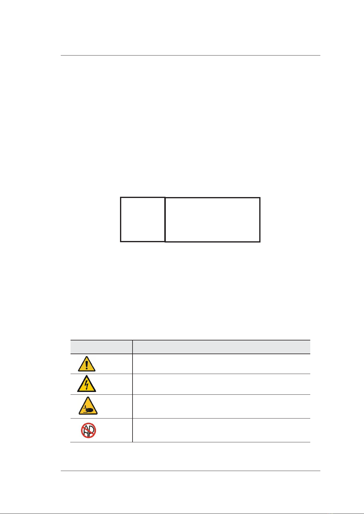
4 Safety Symbols
The following table is provided for your identification of important symbols located in labels on the
ultrasound system.
Symbol
Meaning
Caution
Dangerous voltage
Pinch hazard
Risk of explosion if used in the presence of flammable anesthetics
PAT:
Patient Threshold Temperature
TIP:
Transducer Tip Temperature
PAT: 37℃
TIP: <28℃
1 Safety
Basic User Manual
8
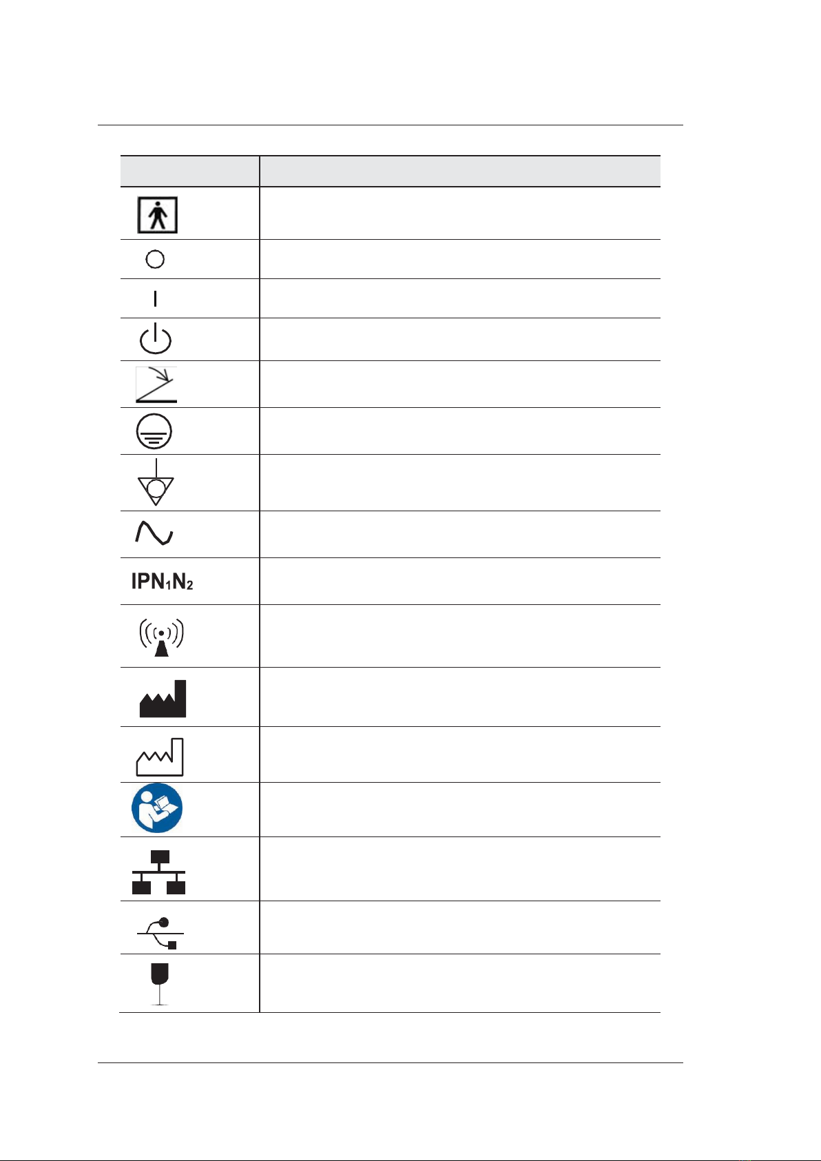
Symbol
Meaning
Type BF Applied Part
Main switch OFF
Main switch ON
On/Standby switch
Footswitch Connector
Protective earth (ground)
Equipotentiality
Alternating current
Degree of IP protection
Non-ionizing electromagnetic radiation.
Manufacturer
Date of manufacture
Follow instructions for use
Network Port
USB Port
Fragile
Table of contents
Other MediSono Medical Equipment manuals


Popular Medical Equipment manuals by other brands


Getinge
Getinge Arjohuntleigh Nimbus 3 Professional Instructions for use

Mettler Electronics
Mettler Electronics Sonicator 730 Maintenance manual

Pressalit Care
Pressalit Care R1100 Mounting instruction

Denas MS
Denas MS DENAS-T operating manual

bort medical
bort medical ActiveColor quick guide

AccuVein
AccuVein AV400 user manual


