Meditub 2646 User manual

Page 1
WALK-IN TUB MANUAL
OPERATING INSTRUCTIONS
INSTALLATION & OPERATING INSTRUCTIONS
INSTALLATION & OPERATING INSTRUCTIONS
Model 30x53
Installation Instructions
P: 1-866-633-4882 www.meditub.com
100 East Mineola Avenue, Valley Strem NY 11580
MediTub
Where Safety Meets Luxury
2646
2653
2952
2952WCA
3053
3054
3060
3060BL
3060SI
3060WCA
3260
3660
MODELS


Page 1
WALK-IN TUB MANUAL
OPERATING INSTRUCTIONS
TABLE OF CONTENTS
THANK YOU FOR CHOOSING US! ................................................................................ 2
CONTACT INFORMATION........................................................................................... 2
PRODUCT REGISTRATION* ....................................................................................... 3
SAVE THIS MANUAL! ............................................................................................... 4
UNPACKING THE UNIT.............................................................................................. 5
PRE-INSTALLATION*................................................................................................ 6
INSTALLATION PREPARATION .................................................................................... 7
ELECTRICAL PREPARATION ....................................................................................... 8
INSTALLATION PROCEDURES .................................................................................... 9
DRAIN CONNECTION................................................................................................ 10
CONNECTING THE AUTODRAIN................................................................................... 11
INSTALLATION AND EXTENSION PANELS ...................................................................... 12
FAUCET INSTALLATION............................................................................................. 13
OPERATING SAFETY INSTRUCTIONS............................................................................ 14
OPERATING INSTRUCTIONS ...................................................................................... 16
TUB CONTROLS...................................................................................................... 18
CLEANING AND MAINTENANCE .................................................................................. 19
WARRANTY........................................................................................................... 20
RETURN POLICY ..................................................................................................... 22
PRODUCT REGISTRATION CARD................................................................................. 23
TABLE OF CONTENTS
TABLE OF CONTENTS

Page 2
WALK-IN TUB MANUAL
OPERATING INSTRUCTIONS

Page 3
WALK-IN TUB MANUAL
THANK YOU & CONTACT INFORMATION
THANK YOU FOR CHOOSING US!
Our mission is to help you maintain independence over essential bathing needs and improve the quality of life! This is designed to
be the most accessible, most comfortable walk-in bathtub on the market today! Until recently, if you have difficulty getting in and out
of a bathtub, it was almost impossible for you to take a bath. Wespecialize in accessibility and security. Safe transfers in and out of
the bathtub are the most critical part of bathing safely. We are committed to providing a complete bathing experience for the elderly
and mobility-impaired.
THANK YOU FOR YOUR PURCHASE!
5701 NW 35 Avenue
Miami, FL 33142
Phone 866-633-4882
Fax 866-560-1060
THANK YOU / CONTACT

Page 4
WALK-IN TUB MANUAL
OPERATING INSTRUCTIONS
PRODUCT REGISTRATION
PRODUCT REGISTRATION
PRODUCT REGISTRATION*
*To ensure that your warranty is registered with us, complete,sign and return this registration card within 30 days of the purchase.NOTE:Your warranty will not be recognized
by us unless this card is fully completed and returned to: 5701 NW 35 Avenue Miami,FL 33142.
IMPORTANT
To ensure that your warranty is registered and confirmed with the manufacturer, please take a few moments to complete, sign and
return the Product Registration Card (below) within 30 day.
WARRANTY CONFIRMATION
By returning this Product Registration Card we confirm the date of purchase for your new product. This confirmation will allow us
to process any warranty claims.
PURCHASE REGISTRATION
The information provided on Product Registration Card (found on page 23)will be kept on file with us as an official Purchase
Registration. The completed card should be mailed to :
5701 NW 35 Avenue
Miami, FL 33142

Page 5
WALK-IN TUB MANUAL
SAVE THIS MANUAL
SAVE THIS MANUAL!
READ THESE INSTRUCTIONS COMPLETELY BEFORE INSTALLING THE PRODUCTS. FAILURE TO DO SO COULD RESULT IN AN
IMPROPER INSTALLATION AND COULD VOID THE WARRANTY.
RESPONSIBILITY OF THE INSTALLER
THE INSTALLER MUST INSPECT AND WATER-TEST THE PRODUCT PRIOR TO INSTALLATION TO ENSURE THE UNIT IS FREE
OF DEFECT OR DAMAGE. IN THE EVENT OF A PROBLEM, THE UNIT MUST NOT BE INSTALLED. IF THE CRATE OR THE PRODUCT
HAS BEEN DAMAGED DURING SHIPPING, PLEASE CALL US IMMEDIATELY.
THIS PRODUCT MUST BE INSTALLED BY A LICENSED/CERTIFIED CONTRACTOR
LICENSED PLUMBERS AND ELECTRICIANS SHOULD BE EMPLOYED TO INSURE PROPER INSTALLATION. INSTALLERS
ASSUME ALL LIABILITY FOR THE CORRECT INSTALLATION PROCEDURES. ONLY ACCESSORIES AUTHORIZED BY THE
MANUFACTURER SHOULD BE USED WITH THIS PRODUCT.
WARNING! WHEN USING THIS PRODUCT, BASIC PRECAUTIONS SHOULD ALWAYS BE FOLLOWED.
READ AND FOLLOW ALL INSTRUCTIONS PERTAINING TO RISK OF FIRE, ELECTRICAL SHOCK, AND/
OR OTHER INJURIES.
IMPORTANT SAFETY INSTRUCTIONS. INSTRUCTIONS IMPORTANTES RELATIVES A LA SECURITE.
READ AND FOLLOW ALL INSTRUCTIONS. LIRE ET SUIVRE TOUTES LES INSTRUCTIONS.
SAVE THESE INSTRUCTIONS. CONSERVER CES INSTRUCTIONS.
WARNING: RISK OF ACCIDENTAL INJURY OR DROWNING; CHILDREN SHOULD NOT USE HYDROMASSAGE BATHTUB
WITHOUT ADULT SUPERVISION. AVERTISSEMENT. RISQUE DE BLESSURE ET DE NOYADE. NE PAS LAISSER UN ENFANT
UTILISER LA CUVE A REMOUS EN L’ABSENCE D’UN ADULTE
WARNING: TO AVOID INJURY, EXERCISE CARE WHEN ENTERING OR EXITING THE HYDROMASSAGE BATHTUB.
AVERTISSEMENT. POUR EVITER LES BLESSURES, USER DE PRUDENCE EN ENTRANT DANS LA CUVE A REMOUS ET EN LA
QUITTANT.
WARNING:RISKOFELECTRICSHOCK;DONOTPERMITELECTRICAPPLIANCES(SUCHASAHAIRDRYER,LAMP,TELEPHONE,
RADIO,ORTELEVISION)WITHIN1.5MOFTHISHYDROMASSAGEBATHTUB.AVERTISSEMENT.RISQUEDECHOCELECTRIQUE.
NE PAS PLACER D’APPAREILS ELECTRIQUES (LUMINAIRE, TÉLÉPHONE, RADIO, TELEVISEUR, ETC.) A MOINS DE 1.5 M DE
CETTE CUVE A REMOUS.
CAUTION:TESTTHEGROUNDFAULTCIRCUITINTERRUPTERPROTECTINGTHISAPPLIANCEPERIODICALLYINACCORDANCE
WITH THE MANUFACTURER’S INSTRUCTIONS. ATTENTION. VERIFIER REGULIEREMENT LE FONCTIONNEMENT DU
DISJONCTEUR DE FUITE A LA TERRE CONFORMEMENT AUX INSTRUCTIONS DU FABRICANT.
SAVE THIS MANUAL

Page 6
WALK-IN TUB MANUAL
OPERATING INSTRUCTIONS
IMPORTANT SAFETY INSTRUCTIONS!
INSTRUCTIONS PERTAINING TO A RISK OF FIRE, ELECTRIC SHOCK, OR INJURY TO
PERSONS
WARNING – WHEN USING THIS UNIT, BASIC PRECAUTIONS SHOULD ALWAYS BE FOLLOWED,
INCLUDING THE FOLLOWING:
READ AND FOLLOW ALL INSTRUCTIONS.
DANGER: TO REDUCE THE RISK OF INJURY, DO NOT PERMIT CHILDREN TO USE THIS UNIT UNLESS THEY ARE CLOSELY
SUPERVISED AT ALL TIMES.
USE THIS UNIT ONLY FOR ITS INTENDED USE AS DESCRIBED IN THIS MANUAL. DO NOT USE ATTACHMENTS NOT
RECOMMENDED BY THE MANUFACTURER.
NEVER DROP OR INSERT ANY OBJECT INTO ANY OPENING.
DO NOT OPERATE THIS UNIT WITHOUT THE GUARD OVER THE SUCTION FITTING.
THE UNIT MUST BE CONNECTED ONLY TO A SUPPLY CIRCUIT THAT IS PROTECTED BY A GROUND-FAULT CIRCUIT-
INTERRUPTER (GFCI). SUCH A GFCI SHOULD BE PROVIDED BY THE INSTALLER AND SHOULD BE TESTED ON A ROUTINE
BASIS. TO TEST THE GFCI, PUSH THE TEST BUTTON. THE GFCI SHOULD INTERRUPT POWER. PUSH THE RESET BUTTON.
POWER SHOULD BE RESTORED. IF THE GFCI FAILS TO OPERATE IN THIS MANNER, THE GFCI IS DEFECTIVE. IF THE GFCI
INTERRUPTS POWER TO THE BATHTUB WITHOUT THE TEST BUTTON BEING PUSHED, A GROUND CURRENT IS FLOWING,
INDICATING THE POSSIBILITY OF AN ELECTRIC SHOCK. DO NOT USE THIS HYDROMASSAGE BATHTUB. DISCONNECT THE
HYDROMASSAGE BATHTUB AND HAVE THE PROBLEM CORRECTED BY A QUALIFIED SERVICE REPRESENTATIVE BEFORE
USING.
(FOR PERMANENTLY CONNECTED UNITS) A GREEN-COLORED TERMINAL (OR A WIRE CONNECTOR MARKED G, GR, GROUND,
OR GROUNDING) IS PROVIDED WITHIN THE TERMINAL COMPARTMENT. TO REDUCE THE RISK OF ELECTRIC SHOCK,
CONNECT THIS TERMINAL OR CONNECTOR TO THE GROUNDING TERMINAL OF YOUR ELECTRIC SERVICE OR SUPPLY PANEL
WITH A CONDUCTOR EQUIVALENT IN SIZE TO THE CIRCUIT CONDUCTORS SUPPLYING THIS EQUIPMENT.
SAVE THESE INSTRUCTIONS!

Page 7
WALK-IN TUB MANUAL
OPERATING INSTRUCTIONS
CLEANING AND MAINTENANCE
Pump and pipe circulation systems should be flushed before first use and on a monthly basis when product is under normal use.
WARNING! NEVER OPERATE THE WHIRLPOOL JETS WHEN TUB IS EMPTY.
Below are the recommended procedures for cleaning:
• Do not run whirlpool dry. Fill the tub with hot water 2-3 inches above the jets and add 2-3 teaspoons of low foaming
detergent such as dishwashing machine detergent - Do NOT use harsh chemicals
• Turn on whirlpool system and run for 10 minutes
• Drain tub completely
• Fill tub with cold water above jets
• Turn on whirlpool system and run for 15 minutes
• Drain tub completely
• Cleaning the suction cover: Clean and remove any hair or lint from the suction cover (see image below). On a monthly basis,
unscrew the suction cover and clean away any hair, lint or debris from the cover and housing, then remount the cover in place. Some
suctions are not designed to be removed; only suctions that have screws on the cover, visible from the inside of the tub, can be
removed.
WARNING! NEVER OPERATE THE UNIT WITH THE SAFETY SUCTION COVER OFF.
SUCTION COVER

Page 8
WALK-IN TUB MANUAL
OPERATING INSTRUCTIONS
UNPACKING
UNPACKING
UNPACKING THE UNIT
INSPECTING THE PACKAGING
Inspect the carton. If any damages are noted, photograph the damaged area(s) and notify the deliverer/carrier.
LIFTING / TRANSPORTING
Never lift the walk-in bathtub by the plumbing. Doing so may result in damaging the plumbing and causing a leak.
INSPECTING THE UNIT
Immediately inspect the unit for damage even if there is no carton damage. Once the unit is installed surface damages will be
assumed to be installation related if not reported at this point.
PLACING THE UNIT
Please note that an installer(s) assumes full liability for damages to the walk-in bathtub after the unit is installed in the “cradle”/niche.

Page 9
WALK-IN TUB MANUAL
SAFETY
SAFETY
PRE-INSTALLATION*
* All Walk-In Bath Tubs are 100% water tested at the factory certified to be free of leaks.Transportation and mishandling may cause leaks. It is necessary to test the bathtub
while there is access to all sides of the bathtub.
READ AND FOLLOW ALL INSTRUCTIONS
• Place the tub on a completely flat surface in an area where it may be drained after testing.
• Close the drain and fill the tub until it is above the highest jet. If it’s a soaker fill up to normal water height level.
• Allow the water to stand in tub for 30 minutes and then inspect all plumbing and seals for leaks.
• If tub is jetted, supply electric to unit and run for 10 minutes and inspect for leaks. Inspect the unions around the pump; if leaks
persist from the unions after tightening; loosen the unions and insure the O-ring is seated properly.
NOTE: IF THE PUMPS DO NOT OPERATE, CHECK THE BREAKER TO ENSURE POWER IS ON AND THE CABLE CONNECTING THE
CONTROLS TO THE PUMP IS ATTACHED.
WARNING! DO NOT RUN ANY PUMPS UNLESS THE TUB IS FILLED WITH WATER TO PROPER
LEVEL. DAMAGE DUE TO DRY RUNNING PUMPS IS NOT COVERED UNDER WARRANTY. FAILURE TO
PERFORM THESE TESTS BEFORE INSTALLATION WILL MAKE THE INSTALLER LIABLE FOR FUTURE
REPAIR COSTS.

Page 10
WALK-IN TUB MANUAL
INSTALLATION PREPARATION
INSTALLATION PREPARATION
INSTALLATION PREPARATION
1. Check the floor area where the tub is to be installed.
• a. Clean area of any debris or trash.
• b. Use a 5 or 6-foot level and determine if the floor is level. If the floor is not level, adjust all 6 leveling feet to perfectly level the tub.
• NOTE: IT IS IMPORTANT THAT ALL LEVELING FEET ARE COMPLETELY TOUCHING THE FLOOR AND LEVEL FOR THE DOOR
SYSTEM TO WORK PROPERLY.
2. Check to ensure that the drain piping has been “roughed-in” at the proper location.
3. Ensure that the proper electrical service has been installed at the pump location. See electrical requirements in the manual (on
following page).
Model 30x53
Installation Instructions
P: 1-866-633-4882 www.meditub.com
100 East Mineola Avenue, Valley Strem NY 11580
MediTub
Where Safety Meets Luxury
Model 30x53
Installation Instructions
P: 1-866-633-4882 www.meditub.com
100 East Mineola Avenue, Valley Strem NY 11580
MediTub
Where Safety Meets Luxury

Page 11
WALK-IN TUB MANUAL
ELECTRICAL PREPARATION
ELECTRICAL PREPARATION
All electrical wiring must be installed in accordance with the National Electrical Code and with all local codes. All wiring shall be done
by a qualified electrician. Run one, two or three branch circuits (as required) from the main electrical service panel to the pump area
of the framing structure to provide power to the unit.
Electrical components have specific wiring requirements. Refer to the matrix below for the electrical supply requirements for the jet
massage bathtub and factory installed components.
Branch circuits must be rated for 110 – 120 volts. Use 12 Gauge, 3 conductor cable for the circuits. If the length run exceeds 100
feet check with local codes for requirements. Install moisture proof junction box(s) 6” above the floor at the pump end of the framing
for each circuit.
NOTE: DO NOT INSTALL THE JUNCTION BOX(S) WHERE IT CAN BE REACHED WHILE SITTING OR STANDING IN THE TUB OR
TOUCHING THE FAUCETS.
AUTO DRAIN™, LIGHTS, WHIRLPOOL, AIR SPA, COMBO & HEATER ELECTRIAL
REQUIREMENTS
This section lists the factory installed components of the Jet Massage and/or Air Massage Systems.
Systems Electrical Rang
Circuit 1
Dedicated
Circuit
Soaker w / Auto Drain™ 15 Amp GFCI
Soaker w / Light
15 Amp GFCI
Soaker w / Auto Drain™ w / Light 15 Amp GFCI
Jet Massage Or Air Massage
15 Amp GFCI
Jet Massage Or Air Massage w / Light 15 Amp GFCI
Jet Massage Or Air Massage w/ Auto Drain™
15 Amp GFCI
Jet Massage Or Air Massage w/ Light & Auto Drain™ 15 Amp GFCI
Jet Massage & Air Massage (Dual)
20 Amp GFCI
Jet Massage & Air Massage (Dual) w/ Light 20 Amp GFCI
Jet Massage & Air Massage (Dual) w/ Auto Drain™
20 Amp GFCI
Jet Massage & Air Massage (Dual) w/ Light & Auto Drain™ 20 Amp GFCI
Whirlpool Inline Heater - Dedicated 15 Amp Circuit
15 Amp GFCI
All electrical connections must be carried out b y a certified electrician in accordance with local electrical requirements and codes.
ELECTRICAL PREPARATION

Page 12
WALK-IN TUB MANUAL
OPERATING INSTRUCTIONS
INSTALLATION PROCEDURES
INSTALLATION PROCEDURES
INSTALLATION PROCEDURES
WARNING! WHEN USING ELECTRICAL PRODUCTS, BASIC PRECAUTIONS SHOULD ALWAYS BE
FOLLOWED, INCLUDING THE FOLLOWING:
DANGER! RISK OF ELECTRIC SHOCK. CONNECT ONLY TO CIRCUIT PROTECTED BY A GROUND
FAULT CIRCUIT INTERRUPTER (GFCI).
GROUNDING IS REQUIRED! THE UNIT SHOULD BE INSTALLED BY A QUALIFIED SERVICE
REPRESENTATIVE AND GROUNDED.
INSTALL THIS UNIT IN ACCORDANCE WITH THE CANADIAN ELECTRICAL CODE, PART I.
INSTALLER CONFORMEMENT AU CODE CANADIEN DE L’ELECTRICITE, PREMIERE PARTIE (CSA
C22.2 NO. 218.2 COMPLIANCE)
NOTE: INSTALLATION MUST PROVIDE ACCESS FOR SERVICING PUMP/MOTOR (ALL TUBS COME WITH AN ACCESS PANEL
FOR THE PUMP/MOTOR).
GENERAL GUIDE-THROUGH
• Install tub waste/overflow according to instructions (see page 10).
• Standard installation - After framing is a complete (see attached diagrams), set product in place to make certain that the tub can
be properly leveled. (Caution: If a walk-in bathtub is not resting on all leveling feet, water will not drain properly and may cause
the door to leak) (see page 7).
• Verify the product’s level by checking tub’s deck surface and ensure all leveling feet are touching the ground (see page 7).
• Electrical connection is made pre-instruction on specified models.
• After plumbing and electrical connections have been made, the tub should be cleaned of dirt and debris.
• Installation is not complete until the tub has been tested in place.
Page 13
WALK-IN TUB MANUAL
INSTALLATION INSTRUCTIONS
INSTALLATION INSTRUCTIONS
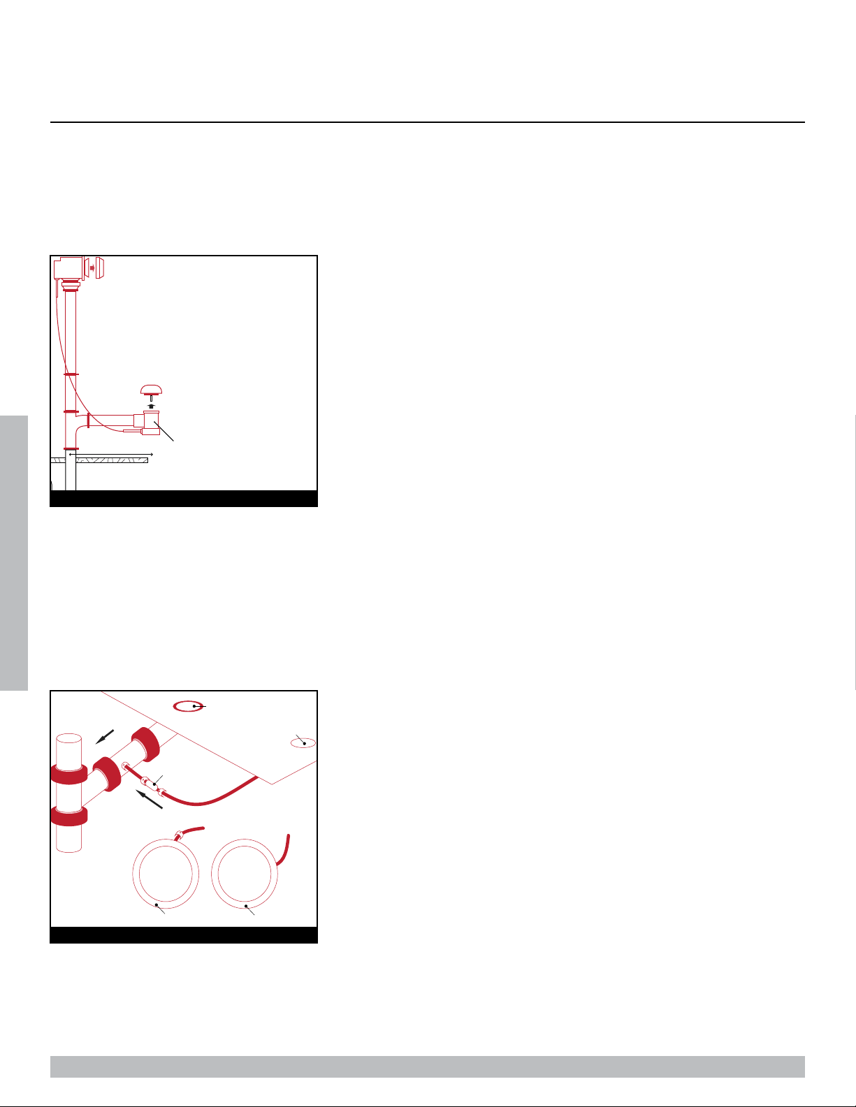
DRAIN CONNECTION
To ensure safe transit for your walk-in tub, the overflow drain components are
not connected to the unit during the process of production. The following in-
structions are provided for installation purposes: Your walk-in tub is supplied
with a 1 ½” drain pipe overflow. The open and close valve with the turn knob
should be attached to the unit at the 1 ½” pre-drilled opening in the wall of the
unit from the outside. The opposite end of the overflow should be attached to
the 1 ½” pre-drilled opening in the foot well of the unit from the underside. The
chrome turn knob and the drain cover should be attached to the appropriate ends
of the overflow drain from the inside of the unit. Place the chrome cap with stem into
thefloordraintocloseofftheopening.Thecableattachedtotheturnknoboftheoverflowisalsoconnectedtoaleverinsidethefloordrain
whichallowsthedraintobeopenedorclosed.Oncethecomponentsoftheoverflowaresecuredintoplace,turntheoverflowknobtothe
openandclosedposition toensureproperfunction.The cap andstemwillmoveupand down, openingand closingthedrain (Figure 1).
Your walk-in tub also has a door drain to remove excess water from the door after
each use. From the underside of the unit, a hose is connected to the door drain with
a check valve. This hose and valve is to provide a one-way flow from the door drain
to the main drain pipe. The check valve will constrict the water flow away from the
door. Insert the opposite end of the hose into the port on the main drain. Be sure the
port is open before attaching the hose. Secure the hose with clamps or ties. Once
the hose is in place, close the door on the unit, place the handle in the locked posi-
tion, and fill tub with at least 12” of water to test the connection. Once the completion
of the drain components are installed and have been tested for proper function, the unit can be leveled and give a final water test
before installation of unit (Figure 2).
1 1/2” Door Drain Pipe supplied7 1/2”
FIGURE 1
Floor Drain
Incorrect
Flow
Door Drain
Correct
Check Valve
Flow
FIGURE 2
Page 14
WALK-IN TUB MANUAL
INSTALLATION INSTRUCTIONS
INSTALLATION INSTRUCTIONS
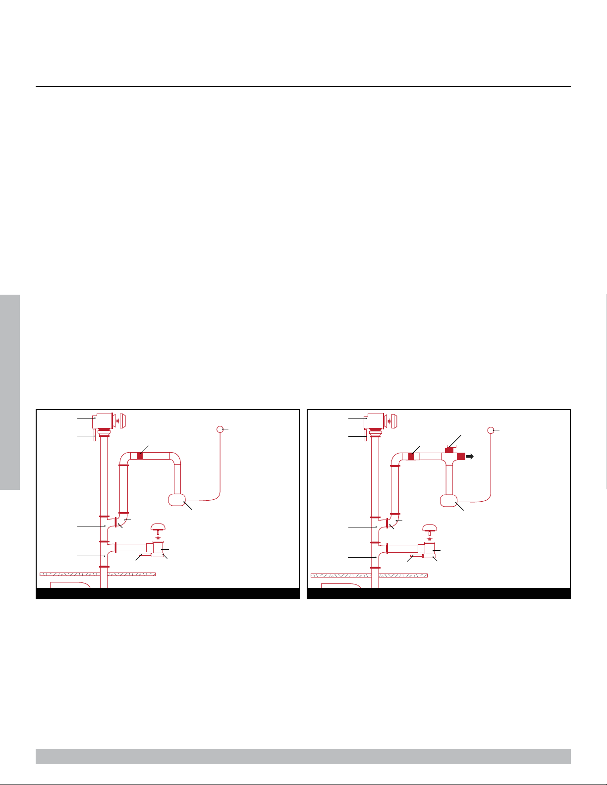
CONNECTING THE AUTODRAIN
HIGH-SPEED AUTODRAIN FOR SOAKING TUB AND/OR AIR SYSTEM
• Drain System requires the connection to a minimum 1 ½ sanitary drain line.
• Use UPC Approved PVC Glue, primer, and Schedule 40 1 ½ ’ pipe.
• Do not change or modify the location and or piping of the Back Flow Preventer.
• The sanitary tee is installed directly above the drain tee with clearance not greater than 1’’.
• Dry fit the drain overflow assembly to the sanitary drainage pipe and check for proper fit.
• Glue the High-Speed Autodrain Fittings, pipe and drain overflow assembly to the sanitary drainage pipe.
• NOTE: WATER TIGHT INSTALLATION OF THE WASTE/ OVERFLOW IS THE INSTALLER’S RESPONSIBILITY. DRAIN LEAKAGE
IS EXCLUDED FROM MEDITUB WARRANTY OF THIS PRODUCT.
NOTE: WE HAVE TAKEN RESPONSIBLE PRECAUTIONS TO ENSURE THE HIGH-SPEED AUTODRAIN IS SUITABLE FOR
RESIDENTIAL PLUMBING. IT IS RESPONSIBILITY OF THE INSTALLER TO INSURE THE SANITARY SYSTEM IS ACCEPTABLE
FOR THE USE OF THE HIGH-SPEED AUTODRAIN. WE DO NOT ACCEPT RESPONSIBILITY FOR DAMAGE ARISING FROM THE
USE OF THE HIGH- SPEED AUTODRAIN.*
*-Ensure compliance with local plumbing codes.
110Vt-60hz pump (15 Amp Circuit)
overflow
drain cable
drain cable drain
drain shoe
sanitary tee
drain tee
90° Elbow
reducer 1 1/2-1”
air button (on/off)
back flow preventer
air button (on/off)
diverter valve
jets
overflow
drain cable
drain cable drain
drain shoe
sanitary tee
drain tee
90° Elbow
reducer 1 1/2-1”
back flow preventer
110Vt-60hz pump (15 Amp Circuit)
SOAKER & AIR AUTODRAIN CONNECTION HYDRO & DUAL AUTODRAIN CONNECTION
Page 15
WALK-IN TUB MANUAL
INSTALLATION INSTRUCTIONS
INSTALLATION INSTRUCTIONS
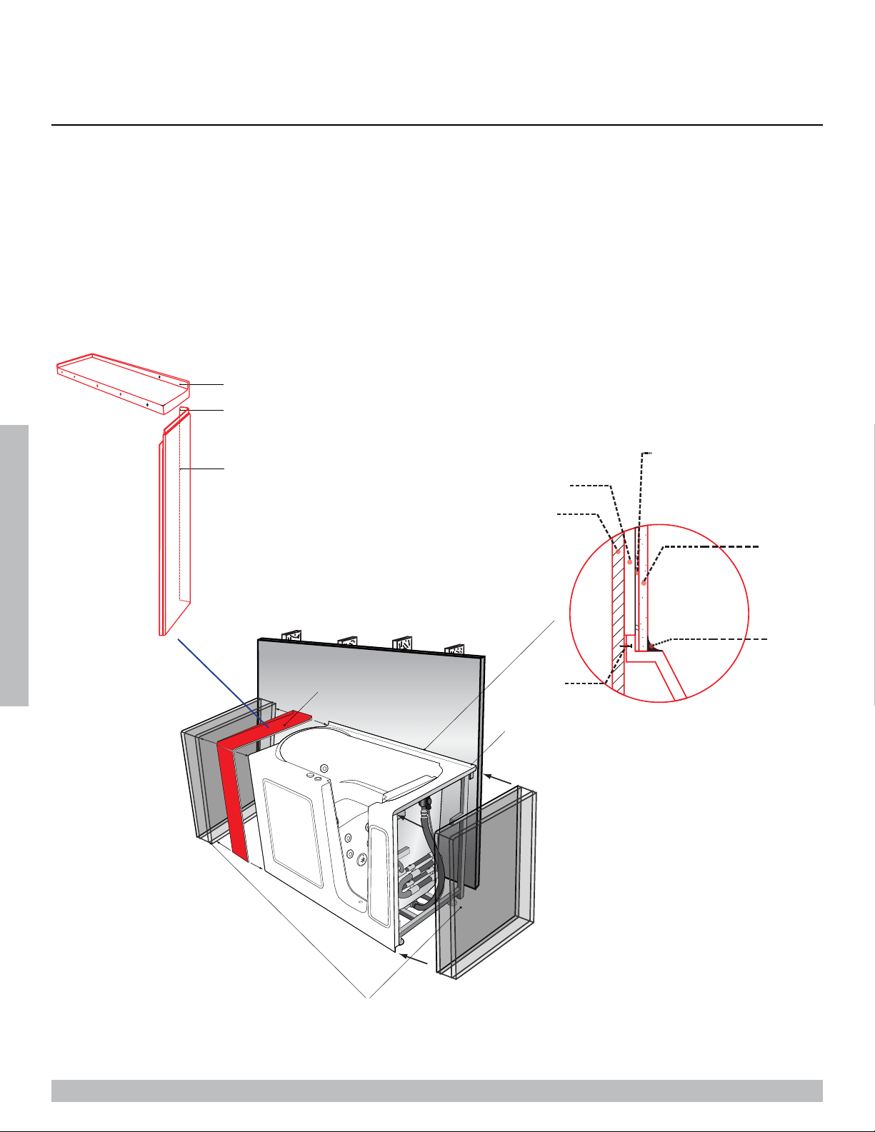
INSTALLATION AND EXTENSION PANELS
ASSEMBLY & PLACEMENT
Connect the two panels using pre-drilled holes:
Inner flange
Top pannel
Side pannel
Wall
Bathroom (Waterproof) Sheetrock
Mortar
Tile
Silicone
Screw
2-piece extension panels
Molded flange to bolt unit to wall
Custom-built wall section(s) for open ends or install against corners of
full wall

Page 16
WALK-IN TUB MANUAL
INSTALLATION INSTRUCTIONS
INSTALLATION INSTRUCTIONS
FAUCET INSTALLATION
fixing nut fixing nut
fixing nut
hot control handle cold control handle
spout shower head
diverter
rubber washer
fiber washer
valve body
gasket
steel braded 19” hose
steel braded 19” hose
72” shower hose
local water line
cold water
hot water

Page 17
WALK-IN TUB MANUAL
OPERATING INSTRUCTIONS
OPERATING SAFETY INSTRUCTIONS
INSTRUCTIONS PERTAINING TO RISK OF FIRE, ELECTRICAL SHOCK OR INJURY
TO PERSONS
WARNING! RISK OF PERSONAL INJURY:
• Use this unit for its intended use as described in this manual. DO NOT use attachments not recommended by the manufacturer.
• To avoid injury, exercise caution when entering or exiting your walk-in tub.
• To reduce the risk of injury, do not permit children or persons with infirmities to use this product unless they are closely
supervised at all times.
• The maximum recommended temperature is 102 F° (38.8 C °). Fifteen minutes per soak is the recommended maximum time at
102 F°, which may induce Hyperthermia which is an increase in body dtemperature. This can be a serious medical condition and
all bath users are cautioned against lengthy immersion at high water temperatures. Should you become light-headed, dizzy, or
nauseous, immediately get out of the bath and cool off.
• Risk of electric shock; do not permit electric appliances (such as a hair dryer, lamp, telephone, radio or television) within four
feet of this bathtub.
• Never drop or insert any objects into any openings.
• Do not operate this unit without the guard over the suction fittings.
WARNING! RISK OF HYPERTHERMIA AND POSSIBLE DROWNING. People using medications, herbal remedies, sleep aids,
and /or having adverse medical history should consult a physician before using this product.
WARNING! NO FOOD OR ALCOHOLIC BEVERAGES. Use of your bathtub immediately after meals is not recommended. Avoid
alcohol consumption before or during the bathing. Alcoholic beverages can cause drowsiness or hyperthermia resulting in loss of
consciousness or even drowning.

Page 18
WALK-IN TUB MANUAL
OPERATING INSTRUCTIONS
The unit must be connected only to a supply circuit that is protected by a ground-fault circuit-interrupter (GFCI). Such a GFCI should
be provided by the installer and should be tested on a routine basis. To test the GFCI, push the test button. The GFCI should interrupt
power. Push the reset button. Power should be restored. If the GFCI fails to operate in this manner, there may be a ground current
flowing, indicating the possibility of an electric shock. Do not use this massage bathtub. Disconnect the jet massage bathtub and
have the problem corrected by a qualified service representative before using.
To reduce the risk of electrical shock, the dedicated electrical supply circuit(s) must be grounded. To do this, connect the third leg of
the 3-conductor wiring cable to the grounding terminal of the electrical service panel and run continuously to the green grounding
screw on the GFCI or electrical receptacle in the wiring compartment.
This manual suits for next models
11
Table of contents
Other Meditub Bathtub manuals


Popular Bathtub manuals by other brands


Kohler
Kohler Stargaze K-24019-GHW quick start guide

American Standard
American Standard Green Tea Whirlpool and Bathing Pool... Specifications

MAAX
MAAX URBAN 6636 installation instructions

Salvatori
Salvatori ONSEN manual

Porcelanosa
Porcelanosa Noken CITY USA 160234 N710001174 manual

TEIKO
TEIKO BASIC user manual

Kingkraft
Kingkraft 1700 installation instructions

Ella
Ella Deluxe 93058 R owner's manual

American Standard
American Standard Reminiscence 2908.018W Specifications

Kingkraft
Kingkraft Lifestyle Preinstallation manual

Kohler
Kohler K-1418-GCR Guide

Ella's Bubbles
Ella's Bubbles WALK IN BATHTUB S Series owner's manual