7
1. Two self-tapping screws and wall plugs have been provided for fast and
simple installation. Simply cut out Template provided for the location of
drill entry points. Use a 8mm masonry drill when fitting control unit to a
brick or concrete wall. When mounting to a post drill pilot holes and fit
screws provided. Once screws are in position simply hang the chlorinator
via the bracket on back of Control Box.
2. Glue the salt cell horizontally on the pool return pipe, allow 24 hour curing
of the pipe glue.
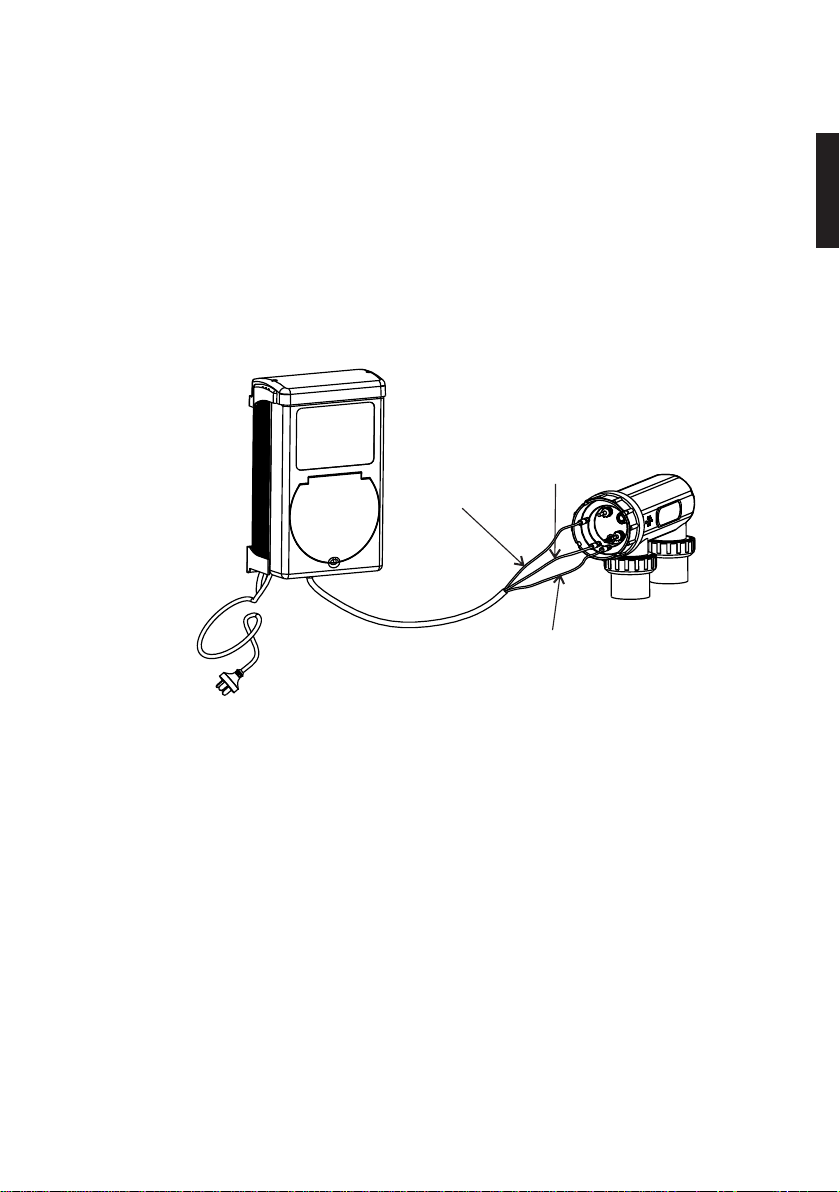
3. Used the provided cable to connect the control unit and the salt cell
together,
IThe single black plug should be connected to the control unit.
IThe yellow wire shall be connected to the gas senor of the Cell
IThe black wires shall be connected to the electrodes; the connectors may
be fitted either way.
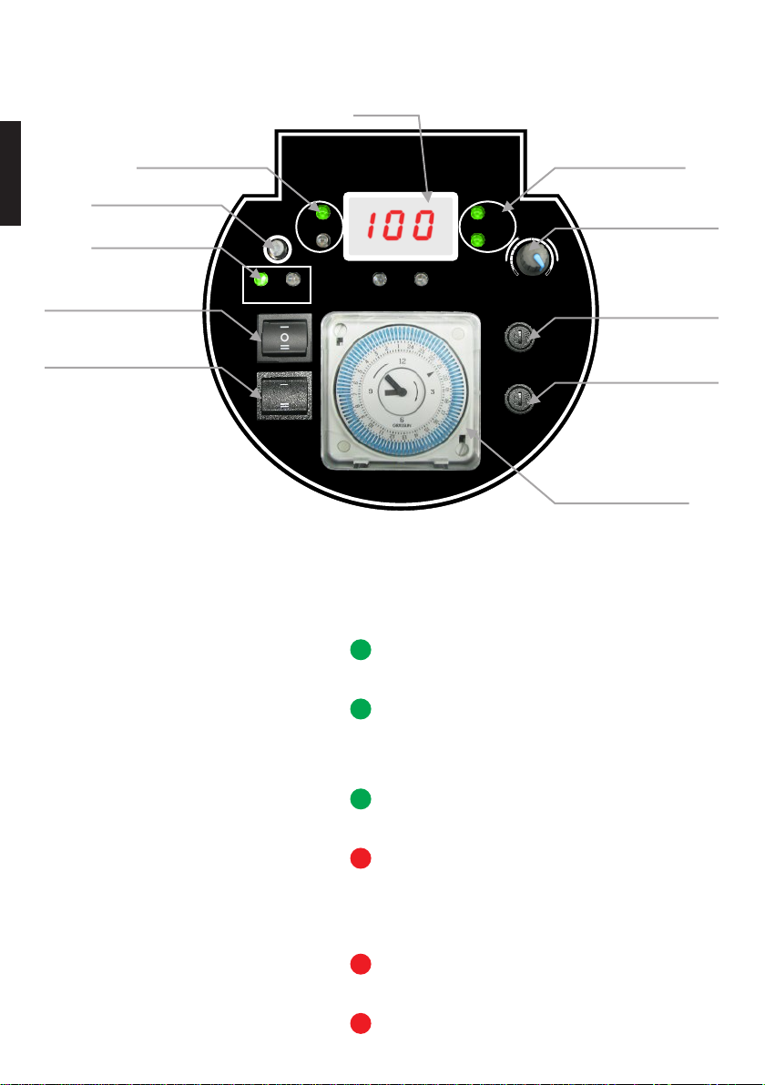
Operation Overview
1. Power input: 220-240VAC, 50/60Hz
2. Recommended pool salt lever: 4000PPM or above (no less than 40kg of
pure salt dissolved in 10,000 liter of pool water)
=Run chlorinator at the Salt Levels stated within this document and on the
product to ensure optimum sanitizer output and cell life.
=Operating this device at low salt levels will damage the cell and reduce its
life.
=The control unit displays a RED indicator when the salt level is low.
=If no action is taken to rectify the salt level, damage to the cell may result
which will not be covered under warranty.
3. During extreme hot weather conditions or high bather load, the pool water
need to be super-chlorinated using granulated or liquid chlorine or
increase the running time of the chlorinator.
4. Always turn down the system control to zero before adding salt, once the
salt is completely dissolved, return to the set position.
5. The aluminum casing at the back of the Control Unit acts as a heat sink, do
not touch it with bare hands.
Black
Yellow
Black
English