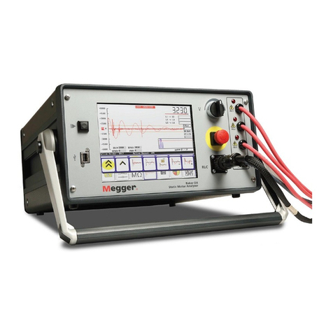
Megger Baker DX User manual


megger.com i
Baker DX
Static Motor Analyzer
User Guide
For use with 4 kV, 6 kV, 6 kV high output (HO),
12 kV, 12 kV HO and 15 kV (Baker DX-15) models
User guide part number: 71-030 EN
Revision: V10
Publication date: April 2020
Copyright 2020, Megger Limited
All rights reserved.
Megger Baker Instruments
4812 McMurry Ave., Suite 100, Fort Collins, CO 80525 USA
Telephone: (970) 282-1200, Fax: (970) 282-1010
Customer Service: 1-800-752-8272
Service department: (970) 282-1200 or toll free at (800) 752-8272.
Web: https://us.megger.com/
Information furnished in this manual by Megger Limited, is believed to be accurate and reliable.
However, Megger Limited assumes no responsibility for the use of such information, for
damages consequent to the use of this product, or for any patent infringements or other rights
of third parties that may result from its use. No license is granted by implication or otherwise
under any patent rights of Megger Limited
NOTICE: No part of this document may be reproduced in part or in full by any means, such as photocopying,
photographs, electronic recording, videotaping, facsimile, and so on without written permission from Megger
Limited
CAUTION:PLEASE READ AND THOROUGHLY UNDERSTAND THE CONTENTS OF THIS ENTIRE
MANUAL BEFORE PERFORMING ANY TESTS WITH THIS PRODUCT.FAILURE TO FOLLOW THE
INSTRUCTIONS AND SAFETY PRECAUTIONS IN THIS MANUAL CAN RESULT IN SERIOUS INJURY,
DAMAGE TO THE PRODUCT,DAMAGE TO OTHER EQUIPMENT,OR A MALFUNCTIONING SYSTEM.
KEEP THIS MANUAL IN A SAFE AND READY LOCATION FOR FUTURE REFERENCE.
This equipment has been tested and found to comply with the limits for a Class A digital device,
pursuant to Part 15 of the FCC rules. These limits are designed to provide reasonable protection
against harmful interference with the equipment if it is operated in its installation. This equipment
generates, uses, and can radiate radio-frequency energy and, if not installed and used in accordance
with the product manual, may cause harmful interference to radio communications. If this
equipment does cause harmful interference, the user is required to correct the interference.

Notices
ii Baker DX 71-030 User Guide EN V10 www.megger.com
Due to the phenomena being observed and the material properties being measured, this equipment
radiates radio frequency energy while in active test mode. Care should be taken to make sure this
radio frequency energy causes no harm to individuals or other nearby equipment.
Megger Acquisition of Baker Instruments
Megger Group Limited, a manufacturer of electronic test equipment and measuring instruments for
power applications, acquired the Baker Instruments business from SKF Group in August of 2018.
For over 50 years, the Baker Instruments business has led the electrical motor testing industry and
has a recognized leading brand and position in this area. As such, legacy products will carry the
Baker Instruments or SKF brands, which will be supported by Megger moving forward.
Megger Baker Instruments Patents
#US04768380 #US05679900 #US05845230 #US05854553
#US05992237 #US06006164 #US06199422 #US06202491
#US06275781 #US06489884 #US06513386 #US06633822
#US6,789,025 #US6,792,360 #US 5,633,811 #US 5,870,699
#WO_03_048714A1

Notices
megger.com iii
Declaration of Conformity
Manufacturer’s Name and Address:
Megger Baker Instruments
4812 McMurry Ave. Suite 100
Fort Collins, CO 80525
USA
Equipment Description: Testers for Surge, DC Hi-Pot, and Winding Impedance of motors.
Equipment Model Designations: DX
Application of Council Directive 72/23/EEC on the harmonization of the laws related to Member
States relating to electrical equipment designed for use within certain voltage limits, as amended by:
Council Directive 93/68/EEC and Council Directive 89/336/EEC on the approximation of the laws
related to Member States relating to the electromagnetic compatibility, as amended by: Council
Directive 93/68/EEC. NOTE due to the phenomena being observed and the material properties being
measured, this equipment does radiate radio frequency energy while in the active test mode.
Referenced EMC Standards Referenced Safety Standards
EMC Directive 2004/108/EC EN 61010-1:2001 Second Edition
IEC 61000-6-2, Second Edition: 2005
IEC 61000-6-4, Second Edition: 2006
CISPR 11:2004
EN 61000-3-2:2006
EN 61000-3-3:2005
I, the undersigned, hereby declare that the equipment specified above conforms to the above
Directives and Standards.
Printed Name: Craig Powers
Title: Quality and continuous improvement leader

Notices
iv Baker DX 71-030 User Guide EN V10 www.megger.com
Instrument Repair and Spare Parts
If the protection of an instrument has been impaired it should not be used, but sent for repair by
suitably trained and qualified personnel. The protection is likely to be impaired if, for example, the
instrument shows visible damage, fails to perform the intended measurements, has been subjected
to prolonged storage under unfavorable conditions, or has been exposed to severe transport stresses.
These products, if defective, should be returned to your supplier in original packaging so that it is
protected from damage during transit. Damage in transit is not covered by this warranty and
replacement/repair is chargeable.
Warranty
New instruments are covered by a one-year warranty from the date of purchase by the user. You will
need to log in, or first register and then login to register your product. Any unauthorized prior repair
or adjustment will automatically invalidate the warranty.
Megger warrants this instrument to be free from defects in materials and workmanship, where the
equipment is used for its proper purpose. The warranty is limited to making good this instrument
(which shall be returned intact, shipping paid, and on examination shall disclose to their satisfaction
to have been defective as claimed). Any unauthorized prior repair or adjustment will invalidate the
warranty. Misuse of the instrument, from connection to excessive voltages, fitting incorrect fuses, or
by other misuse is excluded from the warranty. The instrument calibration is warranted for one year.
This Warranty does not affect your statutory rights under any applicable law in force, or your
contractual rights arising from a sale and purchase contract for the product. You may assert your
rights at your sole discretion
Calibration, Service, and Spare Parts
For service requirements for Baker Instruments products, contact Megger or your local distributor or
authorized repair center. See the back of this guide for Megger contact and Authorized Service
Center details.
Megger operates fully traceable calibration and repair facilities, ensuring your instrument continues
to provide the high standard of performance and workmanship you expect. These facilities are
complemented by a worldwide network of approved repair and calibration companies to offer
excellent in-service care for your products.
Trademarks
Licensee agrees that Surveyor, Surveyor DX, Surveyor EXP, Surveyor NetEP, Baker AWA-IV, Baker DX,
EXP4000, NetEP, MTA or any other software within the Megger Limited—Baker Instruments product
line and the trade dress, logos and other designations of source used by Licensor to identify the
Software are trademarks or registered trademarks of Licensor. Licensee shall not use Licensor’s
trademarks or service marks without the prior written consent of Licensor. If the Software contains
any active links to web sites, you agree to maintain such active links and not redirect or modify them.
Microsoft®, Microsoft Windows®, Microsoft Windows 7 Extended® are registered trademarks of
Microsoft Corporation.
All other trademarks are the property of their respective owners.
megger.com v
Contents
1 — General Operating Information 1
Symbols on Equipment 1
Labels on Equipment 1
Safety Precautions 2
General Operation, Maintenance, and Service Information 6
2 —Baker DX Instrument Overview 7
Front Panel Controls 8
Rear Panel Connections 10
Configuration Options 10
Power Packs 12
Baker ZTX 13
Accessories 14
Surveyor DX 17
3 —Baker DX User Interface Overview 19
Main Elements 19
Test and Function Modes 20
Mode Submenus 20
Popup Menus 23
Other Interface Display Features 24
4 —Using Baker DX Non-Test Functions 29
Data Management Operations 29
Managing Report Printing Operations 35
Using System Settings 41
5 —Setting up the Baker DX Tester 47
Positioning the Baker DX 47
Safety Precautions for Baker DX Setup 47
Baker DX Setup Procedures 47
6 —Setting up the Baker ZTX 49
7 —Setting up Fixtures, Test Accessories, and Lead Connections 51
Overview of Leads, Fixtures, and Accessories Used in Testing 51
Armature Bar-to-bar Test Fixture 52

Table of Contents
vi Baker DX 71-030 User Guide EN V10 www.megger.com
Armature Span Test Fixture 52
Armature Surge Test Accessory Setup 53
ATP02-C Test Clips 55
ATP02-P Test Probes 56
Low-voltage Test Probes 57
Low-voltage Coil Connection 57
Connecting High-voltage Leads to a Motor 58
Connecting Low-voltage Leads to a Motor 59
RIC Test Setup 60
8 —Procedures for Testing with the DX Host 61
Recommended Testing Sequence 61
Coil Resistance, Inductance, and Capacitance Tests Using the DX Host 61
DC Tests Using the DX Host 70
Surge Tests Using the DX Host 77
Partial Discharge Testing Overview and Preparation 81
Partial Discharge Testing–Three-phase Coil Mode 85
Determining a Known-good Coil to Use as a Reference 93
Surge Testing Procedure for Single-Coil Mode 98
Partial Discharge Testing–Single-coil Mode 104
Armature Span Tests Using the DX Host 111
Low-voltage Armature or Coil Tests Using the DX Host 115
Rotor Influence Check (RIC) Tests Using the DX Host 118
9 —Procedures for Testing with the Baker ZTX 123
Low-impedance Armature and Coil Testing Using the Baker ZTX 123
Troubleshooting 127
Self-help and Diagnostics 127
Applications: What to do First 128
Service: What to do First 130
Warranty Return 131
Technical Specifications, Calibration, and Applicable
Standards 133
Calibration Information 135
Applicable Standards 135

Table of Contents
viii Baker DX 71-030 User Guide EN V10 www.megger.com

megger.com 1
1 — General Operating Information
Symbols on Equipment
Table 1. Systems and labels used on equipment.
Symbol/Label Description
Protective conductor terminal. Located beside black ground test lead on
front panel of instrument.
Frame or chassis terminal. Located on rear panel of instrument by
ground terminal. Connects to PPX power pack ground terminal when
used with PPX. Also used to connect to known good ground source
when Open Ground Detect feature is disabled.
Warning about hazardous voltage and risk of injury or death from severe
electrical shock. Located beside each red test lead on front panel of
instrument and on back of unit.
Labels on Equipment
The following Danger notice label appears on the top of the DX unit itself.
Figure 1. High voltage warning label.

General Operating Information
2Baker DX 71-030 User Guide EN V10 www.megger.com
Safety Precautions
Read and follow all safety precautions and safe operating practices in your manual. Do not
exceed maximum operating capabilities of the Baker DX tester, power packs, or the Baker ZTX
accessory.
The general safety information presented here is for both operating and service personnel. You
will find specific warnings and cautions throughout this manual where they apply.
If using the equipment in any manner not specified by Megger Limited, the protection provided
by the equipment may be impaired.
WARNING:Failure to heed the following safety precautions can result in injury
or death from severe electrical shock.
Test Related
Two-party operation is recommended only when using proper equipment (such as the
remote E-Stop) and when taking appropriate precautions so both operators are aware of
all conditions at all times.
Always know what test is being performed and when. For example, do not adjust test
leads when operating a footswitch. Leads will have live voltage and severe electrical
shock may result.
For capacitor-started motors or systems with surge arrestors/power factor capacitors, be
sure to disconnect all capacitors from the test circuit before testing.
Upon completion of any DC-HiPot, MegOhm, polarization index (PI), step voltage, or
dielectric absorption (DA) tests, be sure to short the winding to ground and allow time
for discharge before disconnecting the test leads. If you do not do this, voltage may
build up on the winding. Some industry standards suggest allowing a winding to
discharge four times the total amount of time that DC voltage is applied to the winding.
If the tester is removed from the windings before complete discharge, short winding
leads together and ground them using appropriate jumper cables.
Make sure to disconnect the tester leads before energizing or powering up the motor.
Never attempt to test a winding with both host and power pack leads attached to the
winding at the same time. Damage to the tester will occur.

General Operating Information
megger.com 3
General
Do not remove the product covers or panels or operate the tester without the covers
and panels properly installed. Components on the inside of the tester carry voltage for
operation and can render a shock if touched.
Use appropriate safety equipment required by your organization, including high-voltage
gloves and eye protection.
The devices covered in this manual are not waterproof or sealed against water entry.
The devices covered in this manual are intended for indoor use. If using outdoors, you
must protect the device(s) from rain, snow, and other contaminants.
Repair parts warning: You must replace defective, damaged or broken test leads with
factory-authorized parts to ensure safe operation and maintain performance
specifications.
Ground the product: The devices covered in this manual are grounded through the
power cord’s grounding conductor. To avoid electrical shock, plug the power cord into
a properly wired/grounded receptacle before connecting the product test leads.
WARNING:DANGER FROM LOSS OF GROUND. Upon loss of the protective
ground connection, all accessible conductive parts, including knobs and controls
that may appear to be insulated, can cause an electric shock!
NOTICE: The ground-fault system on the Baker DX will render it inoperative without a proper ground. When
the host Baker DX tester is connected to a power pack, an inoperable condition will also affect the power
pack.

General Operating Information
4Baker DX 71-030 User Guide EN V10 www.megger.com
Equipment Stop Button
The Baker DX tester is equipped with a red Equipment Stop (E-Stop) button on the front panel
of the unit. Use it to quickly discontinue a test and to shut off power to the power pack’s high-
voltage circuitry.
The button will remain locked in position until manually retracted by rotating the Equipment
Stop button clockwise.
Figure 2. Baker DX showing Equipment Stop button.

General Operating Information
megger.com 5
Baker ZTX E-stop and Remote E-Stop
The Baker ZTX unit and the remote E-Stop unit are both equipped with a red Equipment Stop
button. The Equipment Stop button is on top of the Baker ZTX unit and it is in the line with
the status lights on the remote E-Stop accessory.
Figure 3. Baker ZTX unit and Remote E-Stop Equipment Stop buttons.
After being pressed, the button will remain locked in position until manually retracted by rotating
the Equipment Stop button clockwise. A warning message will appear on the DX screen.

General Operating Information
6Baker DX 71-030 User Guide EN V10 www.megger.com
General Operation, Maintenance, and Service Information
Cleaning and Decontamination
Keep the unit clean and in a dry environment. To clean the unit, power down and unplug the
instrument. Wipe with a clean, water dampened cloth. Do not submerge in water or other
cleaners or solvents. To clean the screen, take a soft, water dampened cloth and gently wipe the
surface.
Unpacking the Unit
Carefully remove the following items from the shipping box:
Baker DX
Power cord
Operation manual (digital media only)
Pollution Degree II
(From IEC 61010-1 3.6.6.2) Only non-conductive pollution occurs. However, temporary
conductivity caused by condensation is expected.
Power Requirements
Using the provided AC power cord, connect the unit to a grounded AC power source. The unit’s
power requirements are 100–240 V AC, 50–60 Hz,
2 amps AC maximum current draw. An auto-reset circuit breaker protects the unit.
Environmental Conditions
The unit has been tested for use up to 2,000 m (6,500 ft.).
Only operate the tester in temperatures ranging from 5 to 40° C (41 to 104° F).
This unit is for use at a maximum relative humidity of 80% for temperatures up to
31 °C (88 °F), decreasing linearly to 50% relative humidity at 40° C (104° F). This unit is
intended for Installation Category II in a Pollution Degree II environment.

megger.com 7
2 — Baker DX Instrument Overview
Baker DX Series testers provide a comprehensive, yet modular set of high-voltage motor testing
tools in a compact, lightweight, easy-to-use system. These testers perform Surge, Insulation
Resistance (IR), Inductance, Capacitance, Megohm, Dielectric Absorption (DA), Polarization Index
(PI), and High Potential (HiPot) tests. These units also perform coil and DC motor tests, and have
low-voltage circuit resistance, impedance, capacitance, phase angle, and dissipation
factor/quality factor testing capabilities.
Baker DX testers are compatible with the Baker PP30, Baker PP40, and Baker PP85 power pack
systems for very high-voltage testing, and with the Baker ZTX for armature testing. The DX
family is also compatible with external safety lights and Equipment stop boxes.
Figure 4. Baker DX connected to large motor with low-voltage test connectors for RLC testing;
high-voltage connectors stored safely below cart.

Baker DX Instrument Overview
8Baker DX 71-030 User Guide EN V10 www.megger.com
Front Panel Controls
All Baker DX Series testers feature a large, 8-inch touch screen with a graphical user interface.
The interface features a logical layout of large touch icons that improve ease of use, even with
electrical gloves. The units come with a push-to-test (PTT) lock button that conveniently holds
voltage during DC tests, a variable Voltage Output Control knob to quickly apply voltage
during coil and DC motor tests, and an easily accessible push-button Equipment power shut-off
switch.
Figure 5. Front panel controls.
1. USB printer port
The industry standard USB port is accessible from the front panel for connections to a printing
device, and data storage and retrieval devices.
2. Start or Push-to-Test (PTT) button
The start or Push-to-Test (PTT)button works whether the unit is in standalone mode, attached to
a power pack, or operated with an auxiliary Baker ZTX unit. The PTT operates with a single
touch. A second touch of the button ends a HiPot test when the PTT lock is active. When high-
voltage testing is under way, the PTT conveniently enables voltage discharge of the high-voltage
leads. For tests that require repetitive starts or long duration, an optional foot-operated switch is
available.
3. Touch screen
A high-resolution VGA color touch screen is the main user interface. Large, intuitive icons allow
you to select and configure test types, and display and store test results. The screen also
presents instrument configuration and report printing menus.
4. Equipment power shut-off
This large, highly visible red button is easily pressed on the front panel for Equipment shut-
downs. It cuts all power to the unit swiftly and safely.

Baker DX Instrument Overview
megger.com 9
5. Voltage Output Control knob
Turn the knob clockwise to increase the applied voltage or counterclockwise to decrease the
voltage. The rate of voltage increase or decrease is set via the touch screen interface. Do not
force the knob; turning the knob harder does not cause voltage to ramp any quicker and may
damage the instrument.
6. System unit kV capacity
Each system is clearly marked on the front panel with its voltage capacity.
7. Resistance/inductance/capacitance lead port
Full Kelvin connection leads are used for resistance, inductance, and capacitance testing. Both
sides of the connection clips must be in contact with the terminal of the motor being measured.
8. Low-voltage RLC test leads
Depending on the tester model and options ordered, the tester can have three low-voltage test
leads are provided for motor test connections.
9. High-voltage test leads
Three high-voltage test leads (red) and a ground lead (black) are provided for motor test
connections The Baker DX uses high-voltage test leads for surge, Baker ZTX, and DC testing.
Keep the leads clean and dry for best measurement performance.

Baker DX Instrument Overview
10 Baker DX 71-030 User Guide EN V10 www.megger.com
Rear Panel Connections
The graphic below identifies the connections found on the rear of the DX.
Figure 6. Rear panel connections.
1. DX on/off switch.
2. Remote E-stop and Safety Lights receptacle
3. Footswitch receptacle.
4. DX AC power receptacle.
5. Power Pack interconnect receptacle
Configuration Options
The Baker DX series includes seven models: DX4 (4 kV), DX6 (6 kV), DX6HO (6 kV), DX12 (12
kV), DX12HO (12 kV), the DX15 (15 kV), and the DX15A (15 kV with built-in ZTX). They have
common base functions, but vary by capacity.
The capacity and capability for these models can be augmented with easily-attached auxiliary
units such as power packs that extend the output capacity up to 40 kV (Baker PP30/PPX30, Baker
PP40/PPX40).
You can add low-impedance coil testing to the host with the Baker ZTX 101, or through a Baker
power pack with built-in ZTX capability (such as the Baker PP85/PPX30A).
More information is provided in the following sections.
Table of contents
Other Megger Measuring Instrument manuals

Megger
Megger TTRU3 User manual

Megger
Megger TDR2000/3 User manual

Megger
Megger DET14C User manual

Megger
Megger KF-LAB Mk II User manual

Megger
Megger Baker AWA-IV User manual

Megger
Megger VCLAMP User manual

Megger
Megger DCM2000P User manual

Megger
Megger DCM305E User manual

Megger
Megger PQ2000 User manual

Megger
Megger DLRO-10 User manual

Megger
Megger Surgeflex 8-1000 User manual

Megger
Megger Three-Phase TTR User manual

Megger
Megger DLRO User manual

Megger
Megger DLRO10HDX User manual

Megger
Megger DCM1500S User manual

Megger
Megger MPQ1000 User manual

Megger
Megger DLRO 200 User manual

Megger
Megger BN-19000 User manual

Megger
Megger IDAX Series User manual

Megger
Megger Ducter DLRO2 User manual