Megger TTRU3 User manual

TTRU3
True 3Ø Transformer Turns Ratiometer
USER MANUAL

2 TTRU3 User Manual us.megger.com

Information subject to change without notice 3
TTRU3
True 3Ø Transformer Turns Ratiometer
User Manual
NOTICE OF COPYRIGHT & PROPRIETARY RIGHTS
© 2016-2018, Megger Valley Forge. All rights reserved.
The contents of this manual are the property of Megger Valley Forge. No part of this work may be repro-
duced or transmitted in any form or by any means, except as permitted in written license agreement with
Megger Valley Forge. Megger Valley Forge has made every reasonable attempt to ensure the completeness
and accuracy of this document. However, the information contained in this manual is subject to change
without notice, and does not represent a commitment on the part of Megger Valley Forge. Any attached
hardware schematics and technical descriptions, or software listings that disclose source code, are for infor-
mational purposes only. Reproduction in whole or in part to create working hardware or software for other
than Megger Valley Forgeproducts is strictly prohibited, except as permitted by written license agreement
with Megger Valley Forge.
TRADEMARK NOTICES
Megger®is trademark registered in the U.S. and other countries. All other brand and product names men-
tioned in this document are trademarks or registered trademarks of their respective companies.
Megger Valley Forge is certified according to ISO 9001
Address:
Megger Valley Forge
2621 Van Buren Ave
Norristown, PA 19403 USA
T +1 610 676 8500 sales@megger.com
F +1 610 676 8610 www.megger.com
Document Version: TTRU3_UG_EN_v01

Contents
4 TTRU3 User Manual us.megger.com
Contents
1 Introduction....................................................6
1.1 Receipt of product .........................................6
1.2 Product overview ...........................................6
1.3 Step Up vs Step Down ...................................6
1.4 Model Variation & Accessories .......................7
1.5 Top Panel.......................................................8
1.6 Side Panel......................................................9
1.7 Quick Start & Feet..........................................10
2 Safety..............................................................12
2.1 Responsible User............................................12
2.2 Symbols.........................................................12
2.3 General Precautions.......................................12
2.4 Input Power Precautions ................................13
3 Specifications .................................................14
4 Preparing for test...........................................14
4.1 Site preparations............................................16
4.2 Making Circuit Connections...........................17
4.3 PC Software Installation.................................18
4.4 PC Software Update ......................................19
4.5 PowerDB Installation......................................19
5 Operation .......................................................20
5.1 Initialization & Interface .................................20
5.2 Options..........................................................20
5.3 Confirm/Cancel..............................................20
5.4 Menu Bar.......................................................20
5.5 Home Screen .................................................21
5.6 Help Screen ...................................................21
5.7 Settings Screen ..............................................23
5.8 Measurement & Limits ...................................24
5.9 Transformer Nameplate..................................24
5.10 Regional ......................................................27
5.11 Display.........................................................28
5.12 OLTC ...........................................................29
5.13 Administrative Settings ................................30
5.14 Quick Test Setup ..........................................30
5.15 Test in Progress ............................................31
5.16 Test Failed ....................................................31
5.17 Test Success .................................................32
5.18 OLTC Tap Change Home Screen...................34
5.19 New Test Plan ..............................................36
5.20 Auto OLTC Test in Progress...........................40
5.21 Test failed ....................................................41
5.22 Test plan results ...........................................42

Information subject to change without notice 5
Contents
5.23 Magnetic Balance Test Setup........................44
5.24 Results.........................................................48
5.25 Simulation Mode .........................................51
5.26 PowerDB 3Ø Form ......................................52
6 Service.............................................................54
6.1 Troubleshooting.............................................54
6.2 Maintenance..................................................55
6.3 Calibration.....................................................55
6.4 Repairs...........................................................55

X
1INTRODUCTION
6 TTRU3 User Manual www.megger.com
1.1 Receipt of product
Prior to operation, check for loosened hardware or
damage incurred during transit. If these conditions
are found, a safety hazard is likely, DO NOT attempt
to operate equipment. Please contact Megger as
soon as possible.
1.2 Product overview
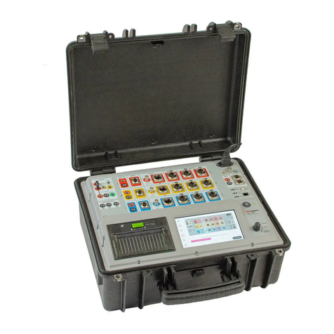
The TTRU3 ratio meter test set is a fully automatic,
self-checking, menu-driven turns ratiometer. The
test set measures the turns ratio, vector relationship,
excitation current as well as transformer diagnostic
health indicators of power, distribution, and instru-
ment transformers. The design of this instrument is
such that it operates properly, independent of line
voltage quality and frequency. This allows use of any
generator driven power source of 500W or higher.
The test set is a lightweight portable instrument
housed in a sturdy plastic case and comes complete
with a canvas carrying bag to hold all accessories.
The test set can be used to test single-phase and
three-phase transformers, both with and without
taps in accordance with the requirements of the IEEE
C57.12.90 – 2013 and IEC 60076-1 standards. For
three-phase measurements, the test set is connected
to all three phases of the transformer to be tested.
The TTRU3 applies all three phases simultaneously
which permits automatic measurement of all phases
without changing connections. The TTRU3 is also
designed to operate single phase on three phase
transformers to help isolate transformer phase re-
lated issues. The TTRU3 measures turns ratio, phase
deviation and excitation current readings which
are displayed on the built in 7 inch color display or
customer PC.
1.3 Step Up vs Step Down
Unlike other transformer ratiometers, the TTRU3
operates in both step up and step down ratio mode.
Step down ratio excites the primary and measures
the induced voltage on the secondary, while step
up excites the secondary and measures the induced
voltage on the primary.
The advantage to step up ratio testing is the ability
to overcome voltage dependence exhibited by large
transformers. As transformers grow in size, more
voltage is required to generate flux. The TTRU3
manages this electrical phenomenon by using the
transformers construction to achieve sufficient flux.

1.4 Model Variation & Accessories
The TTRU3 is available with different hardware
and software configurations. Verify the model you
received is the model that was ordered by observing
the labels on the outside of the instrument and the
version information displayed on the Help screen.
Use the ordering information table below to confirm
that all included accessories, optional accessories,
and required accessories were delivered with your
TTRU3.
ORDERING INFORMATION
Item (Qty) Cat. No. Item (Qty) Cat. No.
3Ø Transformer Turns Ratio Test Set
TTRU3-EXP
TTRU3-PRO
TTRU3-ADV
ADV/PRO Software Options
TTRU3-EXP includes all software options and will receive
automatic activation of new features upon their release
Included Accessories All Automation SW SW-AUTOKIT
AC Adapters & Power Cord - 2.5m (8ft) 2009-874 PowerDB Control SW-POWERDB
USB 2.0 Cable CA-USB Auto OLTC SW-AUTOOLTC
OLTC Tap Changer cable - 9m (30ft) 1011-622 Custom App Control SW-CUSTOMAPP
Cable bag - backpack 2012-180 All Versatile SW SW-VERSATILEKIT
Ground Cable - 5m (16ft) 1011-352 Phase Shifting SW-PHASESHIFT
Thumb Drive 1011-585 Magnetic Balance SW-MAGNETICBAL
Triple Function Pen 2011-538 Optional Hardware Accessories
Required Lead Accessories 1:1 Test Jig 2005-249
Lead P/Ns 2008-XXX-XX (8 total) can be used with the TTRU3 and qual-
ify as required accessories Safety Beacon – 18m (60ft) 1004-639
3Ø universal shielded test lead sets compatible with MTO3XX,
MWA3XX, TTRU3 instruments (up to 10A max), complete with
color-coded Kelvin Clamps: Choose Kit or mix & match H & X
Transit Case (for instrument) 2012-236
TRS1+ Calibration Standard TRS1PLUS
5m (15ft) H & X 2008-15KIT2 TRS1D Calibration Standard TRS1D
9m (30ft) H & X 2008-30KIT2 Calibration Certificate CERT-NIST
18m (60ft) H & X 2008-60KIT2 USB Printer 90029-573
30m (100ft) H & 18m (60ft) X 2008-100KIT2 USB Printer Paper (x48 rolls) 90029-573-P
5m (15ft) H 2008-300-15 OLTC Tap Changer cable
adapters 1011-622-A
5m (15ft) X 2008-301-15 Optional Lead Accessories
9m (30ft) H 2008-300-30 9m (30ft) H extensions 2008-300-30X
9m (30ft) X 2008-301-30 9m (30ft) X extensions 2008-301-30X
18m (60ft) H 2008-300-60 9m (30ft) H &
9m (30ft) X extensions 2008-30XKIT2
18m (60ft) X 2008-301-60
30m (100ft) H 2008-300-100
Introduction
Information subject to change without notice 7

6. Fan
Automatically enabled when internal tempera-
ture exceeds factory limit.
7. Warning Indicator
Indicates when voltage is applied to test leads.
8. Manual OLTC Control Switch
Controls connected OLTC tap changer up/down.
Requires OLTC cable connected to transformer.
9. Touchscreen
Primary GUI control interface. Designed for out-
door (1100 NITS) and industrial environments.
10. Rotary and Directional Control Knob
Supplemental GUI control interface.
1.5 Top Panel
1. Speaker
Used for sounding countdown for test.
2. AUX Port
Used for connecting auxiliary equipment.
3. USB On the Go
TTRU3 appears as a thumb drive containing PC
SW, user manual, and data sheet.
Enables PC Control after PC SW Installed.
4. USB A
Print, export
5. Emergency Stop
Used to immediately interrupt voltage output.
Prevents tests from starting if engaged.
Rotate clockwise to disengage.
Introduction
8 TTRU3 User Manual us.megger.com

Information subject to change without notice 9
15. Beacon Connection
Optional accessory
Functions similar to Warning Indicator
16. Side panel reference
Quick reference for the various connections
1.6 Side Panel
11. Power Input
IEC 320 interface to mains power.
Integrated fuse holder and filter.
O = Off
I = On
12. OLTC Connection
Used in conjunction with Manual OLTC Control
13. Ground
14. Lead Connections
Latching connectors (press tab to release)
Color coded windings
silver/black for primary/secondary
Color coded phases
red, gold, blue, white
Introduction

18. Feet
Rotate out to provide a better viewing angle.
17. Quick Start Guide
Safety and connection reference in lid.
1.7 Quick Start Guide
17
18
Introduction
10 TTRU3 User Manual us.megger.com

Information subject to change without notice 11
Introduction

X
2SAFETY
12 TTRU3 User Manual www.megger.com
2.1 Responsible User
Only qualified and trained operators should operate
the TTRU3. Operator must read and understand
this entire Instruction Manual prior to operating the
equipment. Operator must follow the instructions
of this Instruction Manual and attend the equip-
ment while the equipment is in use. In the event of
equipment malfunction, the unit should immediately
be de-energized and returned to Megger for repair.
The Safety precautions herein are not intended to
replace your Company’s Safety Procedures. Refer to
IEEE 510 - 1983, IEEE Recommended Practices for
Safety in High-Voltage and High-Power Testing, for
additional information.
2.2 Symbols
Caution, possibility of electric shock
Warning, refer to User Manual
Emergency Stop
2.3 General Precautions
The TTRU3 and the Unit Under Test
(UUT) should both be considered
sources of instantaneously lethal levels
of electrical energy.
Observe the following safety
precautions:
• Observe all safety warnings on the equipment.
They identify areas of immediate hazard that
could result in injury or death.
• Use this equipment only for the purposes
described in this manual. Observe strictly the
Warning and Caution information provided in
this manual.
• Treat all terminals of the TTRU3 and high-volt-
age power equipment systems as potential
electric shock hazards. Use all practical safety
precautions to prevent contact with energized
parts of the equipment and related circuits.
• Use suitable barriers, barricades, or warnings to
keep persons not directly involved with the work
away from test activities.
• Never connect the test equipment to energized
equipment.
• Do not use in an explosive atmosphere.
• Use the grounding and connection procedures
recommended in this manual.
• The ground connection must be the first
made and the last removed. Any inter-
ruption of the grounding connection can
create an electrical shock hazard.
• Always disconnect leads from UUT
before disconnecting them from the
TTRU3

Safety
Information subject to change without notice 13
• Personnel using heart pacemakers should
obtain expert advice on the possible risks before
operating this equipment or being close to the
equipment during operation.
2.4 Input Power Precautions
This instrument operates from a single-phase, sine
wave, power source. It has a three-wire power cord
and requires a two-pole, three-terminal (live, neu-
tral, and ground) type input source. The voltage to
ground from the live pole of the power source must
be within the following rated operating voltage:
85V to 250V, 47 - 63 Hz, 250VA
The neutral pole must be at ground potential. Before
making connection to the power source, determine
that the instrument rating matches the voltage of
the power source. The power input plug must be
inserted only into a mating receptacle with a ground
contact. Do not bypass the grounding connection.
The ground terminal of the input supply cord (green
or yellow/green lead) must be connected to the
protective ground (earth) terminal of the line power
source. The black or brown cord lead is the live (hot)
lead.
The control circuits of the instrument are fuse pro-
tected. Fuse is located in the ON/OFF switch module
on side panel and is replaceable by the operator. To
avoid electric shock and fire hazard, use only the
fuse specified below switch module on side panel.
Before replacing the fuses, disconnect
the power input plug from the live power
source.

X
3SPECIFICATIONS
Input Power
90-264VAC, 47-63Hz, 250VA Max
Output
Voltage: 3Ø, 1 - 48VAC, up to 250V on Primary
Frequency: 50-480Hz
Current: 0.1mA - 1A, Max 1A @ 48V
Turns Ratio Measurement Methods
3Ø Step Up
3Ø Step Down
1Ø Step Up
1Ø Step Down
Turns Ratio Range and Accuracy - Guaranteed
from -20°C to +50°C
Step Down Excitation
25-48V
±0.05% 0.8 - 1000
±0.10% 1001 - 2000
±0.30% 2001 - 15000
±1% 15001 – 50000
1-24V
±0.10% 0.8 - 1000
±0.20% 1001 - 2000
±0.60% 2001 - 15000
Step Up Measurement
25-125V | ADV model
25-250V | EXP / PRO models
±0.05% 0.8 – 200 (most Power Tx)
1-24V
±0.10% 0.8 – 200
5 digit resolution
Excitation Current Measurement
Resolution: 0.1mA 0.1mA - 100mA
1mA 101-1000mA
Accuracy: ± 1% ±0.1 mA
Frequency Measurement
Resolution: 0.1 Hz
Accuracy: ±0.1% ±0.1 Hz
Transformer Phase Measurement
Range: 0 - 360 Degrees
Accuracy: ± 0.05 Degrees
Weight
6.5kg 14lbs
Dimensions
406 x 304 x 254mm 16 x 12 x 8in
Environmental
Operating -20°C to +50°C (-4°F to +122°F)
Storage -30°C to +70°C (-22°F to +158°F)
Relative Humidity 0-90%, non-condensing
Regulatory
Safety
IEC 61010-1:2010 + AMD1:2016
EMI/EMC
IEC 61326-1:2012
RoHS2
EN50581
Vibration/Drop/Shock
MIL-STD-810G
14 TTRU3 User Manual www.megger.com

Touchscreen
180mm (7 in.)
800 x 480 Resolution
1100 NITS
Transformer Testing Standards
IEEE C57.152-2013
IEC 60076-1:2011
AS/NZS 6076 1:2014
CIGRE 445 2011
Case
Ruggedized case with fold out feet
Canvas carrying bag for leads and accessories
Internal/External Data Storage
Up to 2000 sets of 3 phase results internal storage
Transferable via USB 2.0/3.0 thumb drive
Communication/Control Software
180mm (7in) built it display running custom GUI
USB Interface for PC Control running custom GUI
Printer Output
51mm (2in) thermal printer
Prints all measurement data displayed on GUI
Specifications
Information subject to change without notice 15

X
4PREPARING
FOR TEST
4.1 Site Preparation
Choose a location that meets the following condi-
tions:
• The location is as dry as possible.
• There is no flammable material stored in the
vicinity.
• The test area is adequately ventilated.
• The test area is flat surface.
• Be sure all equipment is de-energized and all
terminals of the UUT are accessible.
• Erect suitable safety barriers to protect the oper-
ator from traffic hazards and to prevent intru-
sion by unauthorized personnel. User provided
Warning lights are recommended.
• Verify that the Local station ground is intact and
has impedance continuity to earth.
Ensure UUT is completely de-energized.
Check every winding. Ensure all terminals
are disconnected from line or load at the
UUT. Grounds may be left in place.
For all testing described herein, care shall
be taken to ensure any and all unused
clamps are isolated from each other, from
ground, and from personnel.
16 TTRU3 User Manual www.megger.com

1. Ground
Use the Megger supplied Safety Ground Cable
to connect the TTRU3 ground terminal directly
to local station earth ground. Ensure that the
transformer chassis also has a low impedance
connection to local station earth ground poten-
tial.
2. Input Power
Ensure the Input Power Source meets the re-
quirements as listed in Section 2 Safety and Sec-
tion 3 Specifications. Make sure ON/OFF switch
is in the OFF position. Connect power cable to
the TTRU3 first, then to the source. At this time,
leave the ON/OFF switch in the OFF position.
3. Primary & Secondary/Tertiary leads to
TTRU3
With the clamps disconnected from the UUT,
connect the primary and secondary/tertiary leads
to the TTRU3. Be sure that all plugs are fastened
securely to the TTR so they will not become
loose even in the event of the operator inadvert-
ently tripping over the leads.
4. Primary & Secondary/Tertiary leads to UUT
When testing high-voltage transformers, caution
must be used at all times and all safety precau-
tions followed. Read, understand, and employ
all safety precautions and circuit connections
described above and in Sections 2 Safety.
Environmental conditions can lead to corrosion
of the UUT terminals. Ensure that the leads are
making direct contact with metal.
4.2 Making Circuit
Connections
Connections should be made in the order
listed below.
Use leads of appropriate length for the UUT. Ensure
leads are not tightly coiled, as this may influence the
ratio measurement.
5. OLTC Leads to OLTC
Refer to the OLTC wiring diagram for proper
lead connection.
Preparing for test
Information subject to change without notice 17

4.3 PC Software Installation
Before installing PC software, contact your
IT department. Your IT department can
assist with install and provide administrator
approval if required.
The TTRU3 can be controlled from the Touchscreen
or from a connected PC with the PC SW installed. To
install the PC SW:
1. Insert the included thumb drive
-OR-
Connect the TTRU3 to your PC with the included
USB Cable and turn the TTRU3 on. After initiali-
zation, a CD drive will appear on your PC which
contains the software
-OR-
Download the latest PC SW from www.megger.
com/TTRU3
2. Locate the file named TTRU3_installer_X.xx.exe.
X.xx is the version.
3. Double click to launch the installer.
4. Select a Language for the install and click OK.
5. Click Next.
6. Review License Agreement and Click I Agree.
7. Choose components and Select Next.
Defaults recommended.
8. Select Destination folder and click Install.
Defaults recommended.
9. Click Finish to complete the installation.
Preparing for test
18 TTRU3 User Manual us.megger.com

Information subject to change without notice 19
4.4 PC Software Update
If a previous version of PC Software is installed, you
will be required to uninstall before installing the new
version.
1. Locate the installer for the TTRU3 TTRU3_install-
er_X.xx.exe.
X.xx is the version.
2. Double click to launch the installer.
3. Click OK to remove the previous version.
4. Click Next
5. Click Next
6. Click Uninstall.
7. Click Finish.
8. Proceed with the installation instructions in
section 4.3.
4.5 PowerDB Installation
TTRU3 data can be imported into PowerDB. In ad-
dition, the TTRU3 can be controlled from PowerDB.
To install PowerDB, download the latest version
from www.powerdb.com. Follow the instructions on
screen to install PowerDB.
When prompted, choose to install the optional soft-
ware for the TTRU3 and proceed with the installation
instructions from section 4.3.
Preparing for test

X
5OPERATION
5.3 Confirm/Cancel
Settings can either be saved or discarded using the
buttons below:
5.4 Menu Bar
The Menu bar has three sections
5.4.1 Menu Bar Buttons
Button Description
Confirm
Accept changes
Cancel
Discard changes
Button Description
Available when not on the
Home screen
1 Home
2 Navigation
3 Notification Date & time,
notifications
Information about the
current screen
1 2 3
Button Description
Home
Return to the Home
Screen
Emergency Stop
Engaged
Alert
Displays error message
PC Connected
See Connected PC info
5.1 Initialization & Interface
Turn on the TTRU3 using the Input AC Module. A
boot screen with the Megger Logo will appear,
followed by a Loading bar, then the Home Screen.
The TTRU3 graphical user interface (GUI) utilizes a
resistive touchscreen. Gloves or moisture will not
interfere with operation of the touchscreen.
The rotary control knob can also be used to control
the TTRU3. To enable the control knob, use the di-
rectional functions. A yellow highlight will show the
cursors current position.
5.2 Options
Options are displayed a few different ways within
the TTRU3. A brief explanation can be found below:
Option Type Description
Pills
Multiple Selection
Rotary Knob
When less than seven
options are available, pills
are displayed. The largest
pill indicates which option
is selected.
When seven or more
options are available, a
multiple selection screen
is displayed. Use page left/
right and first/last buttons
to navigate.
When displayed, indicates
that values can be changed
using the rotary knob.
20 TTRU3 User Manual www.megger.com
This manual suits for next models
3
Table of contents
Other Megger Measuring Instrument manuals

Megger
Megger DCM1500S User manual

Megger
Megger DCM1500 User manual

Megger
Megger DLRO User manual

Megger
Megger DCM2000P User manual

Megger
Megger MPQ1000 User manual

Megger
Megger PSI410 User manual

Megger
Megger DLRO100E User manual

Megger
Megger MPQ1000 User manual

Megger
Megger VF3 User manual

Megger
Megger DLRO-10 User manual

Megger
Megger TDR2050 User manual

Megger
Megger TDR900 User manual

Megger
Megger DLRO10HD User manual

Megger
Megger MPQ1000 User manual

Megger
Megger MOM2 Win User manual

Megger
Megger TDR2000/3 User manual

Megger
Megger DCM330 User manual

Megger
Megger NIM 1000 User manual

Megger
Megger ATEC 210415 Series User manual

Megger
Megger BT51 User manual