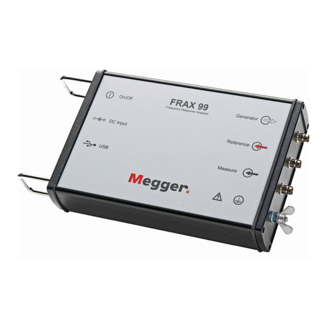
Megger FRAX Series User manual

User guide
FRAX-series
Sweep frequency analyser

FRAX-series • User guide
NOTICE OF COPYRIGHT & PROPRIETARY RIGHTS
2008-2023, Megger Sweden AB. All rights reserved.
The contents of this manual are the property of Megger Sweden AB. no part of this work may be reproduced or transmitted in any
form or by any means, except as permitted in written license agreement with Megger Sweden AB. Megger Sweden AB has made
every reasonable attempt to ensure the completeness and accuracy of this document. However, the information contained in this
manual is subject to change without notice, and does not represent a commitment on the part of Megger Sweden AB. Any attached
hardware schematics and technical descriptions, or software listings that disclose source code, are for informational purposes only.
Reproduction in whole or in part to create working hardware or software for other than Megger Sweden AB products is strictly
prohibited, except as permitted by written license agreement with Megger Sweden AB.
TRADEMARK NOTICES
Megger® and Programma® are trademarks registered in the U.S. and other countries. All other brand and product names mentioned
in this document are trademarks or registered trademarks of their respective companies.
Megger Sweden AB is certied according to ISO 9001 and 14001.
Postal address Visiting address
Megger Sweden AB
Box 724
SE-182 17 Danderyd
Sweden
Megger Sweden AB
Rinkebyvägen 19
SE-182 36 Danderyd
Sweden
T: +46 8 510 195 00
W: www.megger.com

Table of Contents
1. Introduction ............................................................................................................................... 5
1.1. Product description, FRAX ........................................................................................................ 5
1.2. Company website .................................................................................................................... 5
1.3. Receiving Instructions .............................................................................................................. 5
1.4. Support, service & repair ......................................................................................................... 5
1.5. Calibration .............................................................................................................................. 6
1.6. Warranty ................................................................................................................................. 6
1.7. Contact information ................................................................................................................ 7
1.8. Shipping with battery ............................................................................................................... 7
2. General safety ............................................................................................................................ 8
2.1. Symbols on the instrument ...................................................................................................... 8
2.2. Warning and caution notices .................................................................................................... 8
2.3. Accessories ............................................................................................................................. 8
2.4. Cables .................................................................................................................................... 8
2.5. Placement ............................................................................................................................... 9
2.6. Cleaning .................................................................................................................................. 9
2.7. Damaged product ................................................................................................................... 9
2.8. Inputs and outputs .................................................................................................................. 9
2.9. Lightning ............................................................................................................................... 10
2.10. Servicing ............................................................................................................................. 10
2.11. Safety instructions ............................................................................................................... 11
2.12. Battery inside ...................................................................................................................... 12
3. Instrument description ............................................................................................................ 13
3.1. Front panel FRAX 99/101 ....................................................................................................... 13
3.2. Front panel FRAX 150 ............................................................................................................ 14
3.3. Bluetooth Communication (only FRAX 101) ............................................................................. 14
3.4. Built-in battery pack and charger ............................................................................................ 16
3.5. Ground loop detector ............................................................................................................ 17
3.6. Sweep frequency response .................................................................................................... 17
4. Quick start tutorial ................................................................................................................... 19
4.1. Preparatory procedures ......................................................................................................... 19
4.2. Ground loop control .............................................................................................................. 19
4.3. Start FRAX and establish communication ................................................................................ 19
4.4. Create a new test .................................................................................................................. 20
4.5. Test lead connection .............................................................................................................. 21
4.6. Start Measurement ............................................................................................................... 24
5. FRAX Software ........................................................................................................................... 26
5.1. Installing FRAX Software ......................................................................................................... 26
5.2. Overview ............................................................................................................................... 26
5.3. File Menu .............................................................................................................................. 28
5.4. Edit menu ............................................................................................................................. 36
5.5. Conguration menu ............................................................................................................... 36
5.6. Windows menu ..................................................................................................................... 46
5.7. Action buttons ...................................................................................................................... 47
5.8. Legend ................................................................................................................................. 48
5.9. Usage overview ..................................................................................................................... 49
5.10. File description .................................................................................................................... 49
5.11. Test description ................................................................................................................... 49
5.12. Measurement settings ......................................................................................................... 50
5.13. Views .................................................................................................................................. 50
5.14. Legend action button description ......................................................................................... 51
5.15. Correlation analysis ............................................................................................................. 51
5.16. Exit (Alt+F4) ......................................................................................................................... 52
5.17. Connect .............................................................................................................................. 52
www.megger.com FRAX-series 3
6. Specications ............................................................................................................................ 53
7. Appendix ................................................................................................................................... 55
7.1. Appendix A. Calibration instruction ......................................................................................... 55
7.2. Appendix B Adjusting output voltage ...................................................................................... 58
7.3. Appendix C. Test name settings .............................................................................................. 59
7.4. Appendix D. Cables and clamps ............................................................................................. 62
8. Index .......................................................................................................................................... 65
4 FRAX-series www.megger.com

1. Introduction
Thank you for your trust in Megger.
We have the goal to always oer you a pleasant purchasing experience. The FRAX-series is developed and
manufactured in Sweden by knowledgeable and committed employees. Every day, our team does its best to
oer best in class products and services.
This document contains information regarding the correct use and handling of FRAX-series. Keep this
document at hand when using the product. Please ensure to consult the chapter ‘Safety’. This chapter
contains important information for your personal safety. Read the safety regulations attentively before
using this device.
1.1. Product description, FRAX
Most dielectric and mechanical failures in large power transformers are preceded by mechanical changes
in the winding structure. These displacements in the winding structure may be the result of transportation
damage, short circuit forces, or natural aging eects on the insulating structures used to support the wind-
ings. Detection of these displacements before dielectric failure reduces maintenance costs and improves
system reliability.
FRAX Sweep Frequency Response Analyser (SFRA) is designed to detect winding displacements in power
transformers or faults in the magnetic core. The system provides attenuation signature curves that can
easily be compared for deviations which indicate:
▪Core movements
▪Winding deformations and displacements
▪Faulty core grounds
▪Partial winding collapse
▪Hoop buckling
▪Broken or loosened clamping structures
▪Shorted turns and open windings
1.2. Company website
Occasionally an information bulletin may be issued via the Megger website. This may concern new accesso-
ries, new usage instructions or a software update. Please occasionally check on the Megger web site for
anything applicable to your Megger instruments.
www.megger.com
1.3. Receiving Instructions
This instrument has been thoroughly tested and inspected to meet rigid specications before being ship-
ped. It is ready for use when set up as indicated in this user manual.
▪Check the equipment received against the packing list to ensure that all materials are present. Notify
Megger of any shortage.
▪Examine the instrument for damage received in transit. If damage is discovered, le a claim with the
carrier at once and notify Megger, giving a detailed description of the damage.
1.4. Support, service & repair
Technical support
For technical assistance please contact your local representative or direct your request to Megger in
Sweden.
Introduction
www.megger.com FRAX-series 5

E-mail: [email protected]
Service, repair & calibration
Megger has a wide network of authorized service centers. Please consult your local representative or the
webpage for an up-to date listing.
Service, repair and calibration is also available at the service center at the manufacturing site in Sweden.
E-mail: [email protected]
When sending the instrument, please use either the original packaging or one of equivalent strength. Add
the return authorization number to the address label of the shipping container for proper identication and
quicker handling.
For the service center in Sweden we recommend lling out and packing a service information sheet with the
product. This document can be requested via email ([email protected]) or downloaded via this
link: https://se.megger.com/getattachment/Support/Service-information-form-2022-PDF.pdf?lang=sv-SE
1.5. Calibration
Megger operates fully traceable calibration and repair facilities to make sure your instrument continues
to provide the high standard of performance and workmanship that is expected. These facilities are com-
plemented by a worldwide network of approved repair and calibration companies, which oer excellent
in-service care for your Megger products.
Calibration of FRAX
The instrument is calibrated before leaving the factory. Calibration should be performed minimum every
third year, but yearly calibration is a general recommendation for test instruments.
It is also recommended to perform regular tests to verify the integrity of the complete test system, including
cables and connectors.
The following tests can be performed:
Open test cables attached to FRAX but not con-
nected to any device
Short test cables connected to FRAX and con-
nected to each other in the clamp end
FTB test one measurement with the Field Test
Box (FTB101), which will give a smooth
“hockey stick” shaped curve from -100
dB to 0 dB.
The instrument can be calibrated by Megger or any calibration institute that follows the calibration instruc-
tion given in Appendix A, Calibration Instructions.
1.6. Warranty
Products supplied by Megger are warranted against defects in material and workmanship for a period of
18 monts following shipment. Our liability is specically limited to replacing or repairing, at our option,
defective equipment.
This warranty does not include batteries, lamps, or other expendable items, where the original manufactur-
er’s warranty shall apply. We make no other warranty.
The warranty is void in the event of negligence abuse (failure to follow recommended operating procedures)
or failure by the customer to perform specic maintenance as indicated in this manual.
Introduction
6 FRAX-series www.megger.com

Equipment returned to the factory for repair must be shipped prepaid and insured. Contact nearest
Megger representative for instructions and a return authorization (RA) number. Please indicate all pertinent
information, including problem symptoms. Also specify the serial number and the part number of the unit.
Checklist before calling/emailing for support:
▪Check for power supply/battery of the unit
▪Restart the unit and the computer
▪Try to repeat the operation
▪If any error messages, make a print screen (or a note) and attach to your email
▪When reporting an error please include also the serial number of the unit and software version. If related
to a computer, also include the version of Windows used.
1.7. Contact information
Web page: www.megger.com
Email: [email protected]
Telephone: +46 8 510 195 00
1.8. Shipping with battery
IMPORTANT
The FRAX-series contains batteries, so make sure that current Dangerous Goods Regulations are
complied with. If the battery is suspected to be faulty - do not ship it, either separately or inside
an instrument. Contact Megger in need of support. Consult your shipment supplier or Megger
for advice concerning your specic shipment.
Introduction
www.megger.com FRAX-series 7

2. General safety
▪All safety and operating instructions must be read before using the FRAX-series.
▪All safety and operating instructions for the FRAX-series must be followed.
▪All safety and operating instructions must be retained for future reference.
2.1. Symbols on the instrument
Symbol Description
Caution, refer to accompanying documents.
Protective conductor terminal.
WEEE, Waste Electronic Equipment. Please utilize your local WEEE collection facilities in the dispo-
sition of this product and otherwise observe all applicable requirements.The unit can also be
returned to Megger at any time at no charge for the disposal.
2.2. Warning and caution notices
Warning and caution notices are used throughout this user guide where applicable and should be strictly
observed and followed. These notices appear in the format shown below and are dened as follows:
WARNING
Warning, as used in this manual, is dened as a condition or practice which could result in
personal injury or loss of life.
CAUTION
Caution, as used in this manual, is dened as a condition or practice which could result in
damage to or destruction of the equipment or apparatus under test.
2.3. Accessories
Only use accessories that are recommended by Megger.
2.4. Cables
Only use the approved main detachable cable set with the FRAX-series. Main supply cable shall be rated for
the maximum current for the equipment and the cable shall meet the requirements of IEC 60227 or IEC
60245. Main supply cables certied or approved by a recognised testing authority are regarded as meeting
this requirement.
Connecting cables must be routed so that they are not likely to be walked on nor pinched by items placed
upon or against them. Do not pull on or tie them together. Pay particular attention to the connectors.
To disconnect a cable:
1. Unlock the retainer, in case of an XLR connector.
2. Grasp the connector rmly and pull.
General safety
8 FRAX-series www.megger.com

If an input or output cable becomes damaged, stop using it. Use of a damaged cable may result in re or
electric shock.
2.5. Placement
The FRAX-series must be situated away from any heat sources such as radiators, heat registers, stoves, or
other products that produce heat. Do not place the FRAX-series in areas with excessive dust, mechanical
vibration or shock.
Do not use the FRAX-series near water.
Do not expose the FRAX-series to rain or moisture with open lid.
Do not touch the plug with wet hands. Doing so may result in electric shock.
2.6. Cleaning
Unplug the FRAX-seriesbefore cleaning
Do not use liquid cleaners or aerosol cleaners.
Only use a damp cloth for cleaning.
Stubborn stains may be removed with a cloth lightly dampened with a mild detergent solution.
2.7. Damaged product
Do not use the FRAX-series if the test leads appear damaged.
Do not continue using a damaged FRAX-series. Using a damaged FRAX-series may result in re or electric
shock.
Do not touch a damaged LCD panel directly with bare hands. The liquid crystal, which leaks from the panel,
is poisonous if it enters the eyes or mouth. If any part of the skin or body comes in direct contact with the
panel, please wash thoroughly. If some physical symptoms result, please consult your doctor.
Damage requiring service
Unplug the FRAX-series from all connections and entrust servicing to qualied service personnel under the
following conditions:
▪If any connector is damaged, including main plug.
▪If liquid has been spilled into the FRAX-series.
▪If the FRAX-series has been exposed to rain or moisture.
▪If the FRAX-series does not operate normally (following the operating instructions).
▪If the FRAX-series has been dropped or damaged in any way.
▪If the FRAX-series exhibits a distinct change in performance.
▪If the FRAX-series begins to emit smoke, smell, or make strange noises, disconnect all power connections
immediately and contact your dealer for advice.
2.8. Inputs and outputs
▪Do not exceed the specied input voltage limit on any of the FRAX-series inputs.
▪Do not apply voltage to the outputs.
▪Polarity must be red to + and black to −, Timing AUX channels excluded.
General safety
www.megger.com FRAX-series 9

2.9. Lightning
For added protection of the FRAX-series during a lightning storm, unplug it from the AC outlet and from
all cables connected to the inputs. This will prevent damage to the FRAX-series due to lightning and power
supply surges.
Never touch the plug and power cord if it begins to thunder. Touching them may result in electric shock.
2.10. Servicing
Do not attempt to service the FRAX-series yourself. Opening or removing covers can expose you to danger-
ous voltage and other hazards.
Please entrust all servicing to qualied service personnel.
If you attempt to service the FRAX-series yourself, the warranty will no longer be valid.
In case of return for service, please use either the original transport box or one of equivalent strength.
General safety
10 FRAX-series www.megger.com

2.11. Safety instructions
WARNING
1. It is not possible to eliminate all potential hazards from, and in using, electrical test equip-
ment. For this reason, every eort has been made to point out in this instruction manual the
proper procedures and precautions to be followed by the user in operating this equipment
and to mark the equipment itself with precautionary warnings where appropriate. It is
not possible to foresee every hazard which may occur in the various applications of this
equipment. It is therefore essential that the user, in addition to following the safety rules in
this manual, also carefully consider all safety aspects of the test before proceeding.
2. The test set and the specimen to which it is connected are a possible source of high-voltage
electrical energy and all persons making or assisting in tests must use all safety practice
precautions to prevent contact with energized parts of the test equipment and related
circuits.
3. Persons engaged in the test must stand clear of all parts of the complete high-voltage
circuit, including all connections, unless the test set is de-energized, and all parts of the test
circuit are grounded. Persons not directly involved with the work must be kept away from
test activities by suitable barriers, barricades, or warnings.
4. Treat all terminals of high-voltage power equipment as a potential electric shock hazard.
There is always the potential of voltages being induced at these terminals because of prox-
imity to energized high-voltage lines or equipment.
5. Always ground connection points of the test specimen before connecting any leads from
the test set. Whenever possible, always keep one side of the test specimen grounded at all
times. Always use a safety ground stick to ground any high-voltage conductor.
6. The ground connection on the test set must be the rst made and the last removed. Any
interruption of the grounding connection can create an electric shock hazard.
7. Make sure that the instrument is properly grounded, both through its AC power cord and
through the ground connector. The AC power cord is the disconnecting device.
8. Always disconnect test leads from test specimen before attempting to disconnect them at
the test set.
9. High-voltage discharges and other sources of strong electric or magnetic elds may interfere
with the proper functioning of heart pacemakers. Persons with heart pacemakers should
obtain expert advice on the possible risks before operating this equipment or being close to
the equipment during operation.
10. All persons making or assisting in tests must use all practical safety precautions to prevent
contact with energized parts of the test equipment and related circuits. Also follow all local
and company safety requirements.
11. Safety is the responsibility of the user.
12. Misuse of this high-voltage equipment can be extremely dangerous.
13. The purpose of this equipment is limited to use as described in this manual. Do not use the
equipment or its accessories with any device other than specically described.
14. Before making any connections, make sure that the instrument is de-energized and that all
parts of the test circuit are properly grounded.
15. Never connect more than one output at the time. All outputs are energized by the same
amplier and therefore all outputs are energized simultaneously.
16. Operation is prohibited in rain or snow.
17. Do not use the test set in an explosive atmosphere.
18. Refer all servicing to qualied personnel.
19. A qualied operator should attend all times while the test equipment is in operation.
20. Observe all safety warnings marked on the equipment.
21. Corrective maintenance must only be performed by qualied personnel who are familiar
with the design and operation of the test set and the hazards involved.
Maintenance
General safety
www.megger.com FRAX-series 11

IMPORTANT
1. DISCONNECT the power adapter before any cleaning or maintenance.
2. Maintenance should be performed only by qualied personnel familiar with the hazards
involved with high-voltage test equipment.
3. Refer all servicing to qualied personnel.
4. Routine maintenance is all that is required for these test sets. The cables and connector
panel should be inspected frequently to be sure all connections are tight and all ground
connections intact.
5. The appearance of the test set can be maintained by occasional cleaning of the case, panel,
and cable assemblies. The outside of the carrying case can be cleaned with detergent and
water. Dry with a clean, dry cloth. The control panel can be cleaned with a cloth dampened
with detergent and water. Do not allow water to penetrate panel holes, because damage
to components on the underside may occur. A household all-purpose spray cleaner can be
used to clean the panel. Polish with a soft, dry cloth, taking care not to scratch the display
screen cover. The cables and mating panel receptacles can be cleaned with isopropyl or
denatured alcohol applied with a clean cloth.
2.12. Battery inside
▪This product is not intrinsically safe. Do not use in an explosive atmosphere
▪This instrument contains a lithium battery.
▪Do not pierce, damage, disassemble or modify the battery.
▪The battery contains safety and protection devices, which if tampered with may cause the battery to
generate heat, rupture or ignite.
▪If the battery is suspected to be faulty – do not ship it, either separately or inside an instrument.
▪The instrument must be powered o and securely packaged before shipping.
▪Do not heat or dispose of the battery in a re.
▪Do not subject the battery to strong impact, mechanical shock or excessive heat.
▪Do not short-circuit or reverse the polarity of the battery.
General safety
12 FRAX-series www.megger.com

3. Instrument description
3.1. Front panel FRAX 99/101
1. On / O To turn the instrument on/o
2. DC-input To connect the AC/DC adapter
3. USB USB-connector type B, to connect a USB cable to PC
4. Antenna (only FRAX101) Bluetooth module, enables Bluetooth communication
5. GLD Test Ground loop continuity check
6. Generator (Yellow) Generator output connected to Reference at Red Clip
7. Refereence (Red) Reference input connected to Generator at Red Clip
8. Measure (Black) Measure input Connected to Black Clip
9. Protective Earth/Ground connector Always connect the instrument to station earth/ ground using the sepa-
rate earth/ground cable.The separate earth/ground wire should be the rst connection made and the last removed.
WARNING
All test objects must be grounded at one end at all times to minimize risks for high voltage
interference entering the instrument.
Instrument description
www.megger.com FRAX-series 13

3.2. Front panel FRAX 150
1. Ground (Protective earth) connector Always connect the instrument to station earth/ ground
using the separate earth/ground cable. The separate earth/ground wire should be the rst connection
made and the last removed.
2. Screen backlight control
3. Mains input With fuse 2 A
4. On/O button
5. Network For connecting the FRAX-150 to LAN
6. USB port Four USB ports for accessories such as keyboard, mouse and USB ash drive
7. INT / EXT Switch for internal or external PC
8. USB port For connection of external computer
9. Generator (Yellow) Generator output connected to Reference at Red Clip
10. Reference (Red) Reference input connected to Generator at Red Clip
11. Measure (Black) Measure input Connected to Black Clip
12. GLD Test indicator
13. GLD Test button
14. Touchscreen With built-in software keyboard
3.3. Bluetooth Communication (only FRAX 101)
Bluetooth is a standard for wireless serial communication. Simply speaking, Bluetooth replaces a serial
cable between laptop and FRAX instrument.
The output power of Bluetooth module is divided into three classes:
Power class Max output
power
Expected range
Class 1 100 mW 100 m / 330 ft
Class2 2.5 mW 10 m/33 ft
Class 3 1 mW 1 m /3.3 ft
The Bluetooth module used in FRAX 101 is class 1. Also, the Bluetooth USB Adapter that comes as a stand-
ard accessory with FRAX is class 1. Using this adapter communicating with FRAX, class 1 communication will
be established.
Instrument description
14 FRAX-series www.megger.com

Many laptops of today have in-built Bluetooth capability, most common is class 2. Since the Bluetooth
module used in FRAX 101 has excellent receiving properties, a built-in Bluetooth device may be suitable in
many situations. However, in eld/substation environments Bluetooth class 1 is recommended.
To congure a built-in Bluetooth device, please follow the manufacturers instruction. To congure the Blue-
tooth USB Adapter that comes with the FRAX, install the included Bluetooth software before the adapter is
inserted into the USB-port.
NOTE
It is reported that in some cases an activated built-in Bluetooth and using an external USB
Bluetooth Adapter can create some conicts in Windows. If this happens, uninstallation both
adapters and reinstallation only the one which is intended to be used can solve this issue.
Bluetooth communication must be established rst before attempting to connect the FRAX Software to the
FRAX instrument.
The following steps show how to add a connection between the FRAX instrument and the computer using
built-in Bluetooth functionality. Please note that the procedure is managed by operating system directly.
Thus, the procedure necessary on a particular computer may dier from the following steps, and it should
be regarded as an example.
1. Form Windows start menu open “Devices and Printers” and click on “Add a device”. Computer will list all
available devices.
2. Find device named “Megger FRAX 101” select it and click “Next”. Computer will connect to device.
3. Click on option “Enter the device’s pairing code”.
4. Enter pairing code “0000” and click “Next”
Instrument description
www.megger.com FRAX-series 15

5. Now connection to FRAX unit from the FRAX software can be established.
NOTE
The procedure described above only needs to be done once. Next time the computer is started
simply insert the USB adapter using same USB port or use built-in Bluetooth.
NOTE
If external USB dongle is installed in a dierent USB port of the computer, then the serial COM
port assigned to that USB port may be dierent.
Either connect to other USB port or change the COM port in the FRAX communication setting.
Then start FRAX software and press connect.
TIP
It may be a good idea to remove unused Bluetooth connections from settings as each connec-
tion is checked when FRAX unit is connected. This can be done in the Bluetooth settings in the
Windows Control Panel.
6. It is possible to also set the port to use as a default in the settings le. It is located in C:\Users\...\AppDa-
ta\Roaming\FRAX and named UserAppData.xml.
Open it in Notepad and look for the tag:
Set the port to be used there.
3.4. Built-in battery pack and charger
As an option, FRAX-101 is delivered with a built-in battery pack and charger.
The battery is of Li-Ion type, 4.8 Ah, 11.1 V.
The charger is powered from the standard AC/DC adapter that is delivered with the instrument.
FRAX-101 automatically enters low power consumption mode when waiting for a measurement and be-
cause a typical sweep takes approximately 1 minute, the battery lasts for at least 3 hours of measuring or
more than 12 hours idle.
Instrument description
16 FRAX-series www.megger.com

Charging is performed automatically when the AC/DC adapter is connected. The FRAX-101 does not have to
be turned on. To ensure long battery life, batteries will not be charged if the battery charge is higher than
90 % or if the temperature is above 40 °C. A complete charge takes approximately 8 hours.
The blue LED gives indication of charging status:
LED not lit FRAX turned o, or FRAX is switch-
ed on, battery empty.
LED blinking Charging
LED lit FRAX connected to AC/DC adapter,
Battery is fully charged (or charging
disabled of other reason see above)
LED lit FRAX runs on batteries (AC/DC
adapter not connected)
3.5. Ground loop detector
Embedded ‘Ground Loop Detector’ in FRAX checks the test setup and assures that all connections including
the grounding braids are properly connected. After pressing GLD button on FRAX the green/ red (“Pass/
Fail”) LED shows user status of the ground loop. In case of ‘’Fail’’ signal (red LED), the connections must be
checked. “Pass” signal (green LED) guarantees that the measurement results can be reproducible.
NOTE
Ground loop detector is not available in FRAX 99.
3.6. Sweep frequency response
FRAX “Generator” (Gen.) output generates sinusoidal voltage at a selected frequency. Two separate input
channels, “Reference” (Ref.) and “Measure” (Meas.) measure both the generated voltage and the response
voltage with respect to amplitude and phase.
The instrument stores “Amplitude” and “Phase” data for both “Reference” channel and “Measure” channel as
well as the ratio “Measure” divided by “Reference”. The values can be plotted and exported as Magnitude,
Phase, Impedance, Impedance-Phase, Admittance and more.
The Custom models function make it possible to calculate almost any parameter based on the measured/
stored data.
FRAX uses the sine correlation technique. This means that the input voltages are multiplied by a sine and a
cosine, and then averaged over an integer multiple of the interval of time. The sine, cosine and the voltage
applied have exactly the same frequency. The sine correlation technique is well known and is suitable for
Sweep Frequency Response Analysis (SFRA) measurements. Since the signals on the two input channels are
treated the same way, the phase resolution between these two channels is extremely high. The rejection
of DC oset and harmonics - referred to as the applied voltage - are in theory innite. By increasing the
integration cycles, the rejection gradually improves.
Instrument description
www.megger.com FRAX-series 17

The IF bandwidth is commonly used as a parameter dening the bandwidth around the applied signal
analyzed. An IF bandwidth of 10 % of active frequency is equivalent to 12 cycles of integration.
Instrument description
18 FRAX-series www.megger.com

4. Quick start tutorial
4.1. Preparatory procedures
This tutorial provides an introduction on how to use FRAX and FRAX software. They are intentionally kept
brief so that user can start using the instrument and software as quickly as possible. The objective is not to
teach user every single detail but to familiarize with the basic principles.
IMPORTANT
Always follow the safety instructions in this manual. Always comply with local safety regulations.
1. The transformer must be disconnected from the net, which means that any connection to the trans-
former bushings including neutral(s) must be disconnected.
2. The transformer tank must be properly grounded.
A. If the transformer is equipped with a Load Tap Changer (LTC), the position of the LTC will inuence
the SFRA measurement. The recommendation is to put the LTC in the position to include all tap
windings in circuit (“Extreme Raise” position) and note that this LTC position is used. When making
measurements at several tap positions, make sure to note each tap position.
B. If the transformer is equipped with a De-Energized Tap Changer (DETC), the position of the DETC
will inuence the SFRA measurement. The recommendation is to leave it at the nominal tap position
unless otherwise specied. Make sure to note the DETC position in the Nameplate section of the
software.
3. Connect the FRAX instrument to station earth/ground near the power transformer to be measured
using the separate earth/ ground wire (at bottom of transformer if instrument is operated beside the
transformer, at another good connection to transformer at top of transformer if instrument is used on
top of transformer). The separate earth/ ground wire should be the rst connection made and the last
removed.
4. Connect the test lead BNC connectors to the FRAX instrument, Generator (yellow), Reference (red) and
Measure (black).
5. Connect the AC/DC Adapter to the FRAX and a power source that meets local safety regulations and the
AC/DC Adapter specications or use optional in-built battery supply.
6. If not using Bluetooth communication, connect the USB cable to the FRAX and computer.
7. Turn on the FRAX.
4.2. Ground loop control
1. Press GLD button to verify ground loop continuity.
If LED is red, check ground connections at transformer and bushings.
2. Start FRAX-software on PC and establish communication, see Establish Communication
4.3. Start FRAX and establish communication
▪If using Bluetooth communication: Establish Bluetooth communication, see also detailed description
Bluetooth Wireless Communication. Usually, a serial port number will be assigned, e.g., 8, that should be
used when FRAX establish connection. Note that FRAX Software remembers the last used port.
▪If using US communication: Connect the USB cable to the computer and to the FRAX. The computer
should display a message that it found new hardware
1. Start FRAX software
2. Connect to FRAX by selecting "Connect" from menu File, by clicking "Connect" button on the right hand
side of software window or by using F7 key.
Quick start tutorial
www.megger.com FRAX-series 19

▪If connections are set-up properly the window name will change from “FRAX (Disconnected)” to FRAX
(Connected).
▪If the connection does not work, an error message will appear suggesting what to do, normally selecting
the suggested port number with a green symbol next to it.
4.4. Create a new test
A test starts by creating a sequence of sweeps and decide where to save data by use of “New File”.
1. Use the command “New File” from the File menu or use of Ctrl+N or use of the button “New File”.
2. The “Measurement type” window will appear. In “Measurement type” window, select the tab of choice:
Single Test Makes a test with single sweep and
the test label of choice
Multiple
Test
Makes it possible to select apre-
dened test template design from
“Test groups”
Use Meas-
urement as
Template
Makes it possible to use an earli-
er measurement as template for a
new measurement
A. If “Multiple tests” tab is selected there will be given a choice of dierent pre-dened templates for
dierent transformer designs. Select desired tests to make and press OK. Note that it is always possible
to add new sets of tests with dierent names.
B. If “Quick Test” or “Multiple Tests” in the “Measurement type” dialog is selected, an almost empty
nameplate will appear. The “Test date:” is automatically added from PC system date. Please ll in the
Nameplate data (no eld is required) and press “OK”. The selected measurement sweeps are visible in
the in the Test Browser.
C. If the “Measurement type” “Use Measurement as Template” is used the Nameplate contains the Tem-
plate Nameplate as default, except the “Test Date” that is automatically added from PC system.
3. Enter Nameplate information and press “OK”. A “Save As...” dialog appears where the le structure and a
name of choice can be selected. The default directory will be My Documents\FRAX on rst start and then
the directory used last time. The le name will be formatted as selected in default lename settings. Click
“Save” to save the le.
NOTE
Information can always be added to the “Nameplate” at any time. This feature makes it possible
to add notes during the measurement.
Quick start tutorial
20 FRAX-series www.megger.com
Table of contents
Other Megger Measuring Instrument manuals

Megger
Megger MOM200A User manual

Megger
Megger DCM320 User manual

Megger
Megger KF-LAB Mk II User manual

Megger
Megger MOM690 User manual

Megger
Megger VCLAMP User manual

Megger
Megger DLRO10HD User manual

Megger
Megger HT1000/2 User manual

Megger
Megger DLRO10HD User manual

Megger
Megger MIT400/2 Series User manual

Megger
Megger DET14C User manual

Megger
Megger Ducter DLRO2 User manual

Megger
Megger BT51 User manual

Megger
Megger DLRO-10 User manual

Megger
Megger DET14C User manual

Megger
Megger DCM300E User manual

Megger
Megger BERT-20E1 User manual

Megger
Megger Surgeflex 8-1000 User manual

Megger
Megger DLRO User manual

Megger
Megger Ducter DLRO2 User manual

Megger
Megger CP-600DC-ID User manual