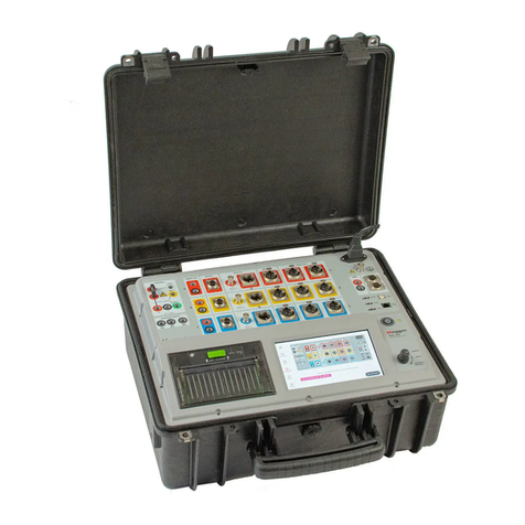
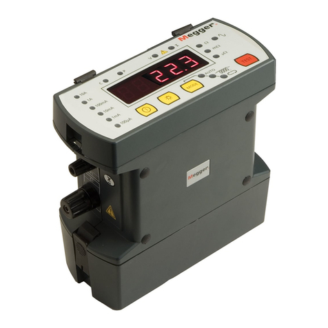
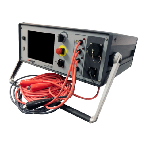
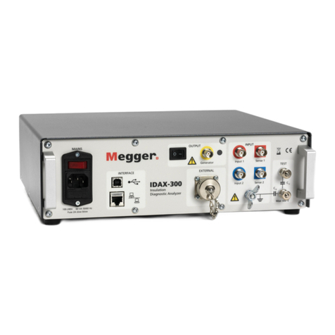
Megger IDAX 300 User manual

User guide
Art No. ZP-AG03E Doc. AG033586EE V06a 2020
IDAX 300/322/350
IDAX 5 Software
Insulation diagnostic analyzers


IDAX 300/322/350
IDAX 5 Software
Insulation diagnostic analyzers
NOTICE OF COPYRIGHT & PROPRIETARY RIGHTS
© 2013-2020, Megger Sweden AB. All rights reserved.
The contents of this manual are the property of Megger Sweden AB. No part of this work may be reproduced or transmitted in any form or
by any means, except as permitted in written license agreement with Megger Sweden AB. Megger Sweden AB has made every reasonable
attempt to ensure the completeness and accuracy of this document. However, the information contained in this manual is subject to change
without notice, and does not represent a commitment on the part of Megger Sweden AB. Any attached hardware schematics and technical
descriptions, or software listings that disclose source code, are for informational purposes only. Reproduction in whole or in part to create
working hardware or software for other than Megger Sweden AB products is strictly prohibited, except as permitted by written license
agreement with Megger Sweden AB.
TRADEMARK NOTICES
Megger® and Programma® are trademarks registered in the U.S. and other countries. All other brand and product names mentioned in this
document are trademarks or registered trademarks of their respective companies.
Megger Sweden AB is certified according to ISO 9001 and 14001.
User guide
Postal address:
Megger Sweden AB
Box 724
SE-182 17 DANDERYD
SWEDEN
T+46 8 510 195 00
Eseinfo@megger.com www.megger.com
Visiting address:
Megger Sweden AB
Rinkebyvägen 19
SE-182 36 DANDERYD
SWEDEN
AG033586EE ZP-AG03E IDAX 300/322/350 3

4IDAX 300/322/350 ZP-AG03E AG033586EE
Contents
1 Introduction
............................................................... 6
1.1 Product description......................................6
1.2 Features and benefits...................................6
1.3 Warranty .....................................................7
Receiving instructions.................................................. 7
Warranty repair ........................................................... 7
1.4 Service and support .....................................7
Contact information.................................................... 7
2 Safety
............................................................... 8
2.1 General........................................................8
Symbols ..................................................................... 8
Information duty regarding substances on REACH
article 33, SVHC-list ................................................... 8
Warning and caution notices....................................... 8
Instrument safety ........................................................ 8
2.2 Safety instructions........................................9
Maintenance............................................................... 9
3 Instrument description
............................................................. 12
3.1 Front panel IDAX 300 ................................12
3.2 Front panel IDAX 322 ................................13
3.3 Front panel IDAX 350 ................................14
3.4 Standard accessories..................................15
3.5 Installation.................................................15
Installation of IDAX 5 software.................................. 15
3.6 Preparing instrument .................................16
3.7 Preparing test object..................................16
3.8 IDAX 322 Interlock positions......................17
3.9 Configurations and connections.................17
Measurement terminals............................................. 17
Test modes................................................................ 17
Connection examples – Power transformers .............. 17
4 IDAX 5 Software
............................................................. 20
4.1 Moisture test .............................................20
Start the IDAX 5 software ......................................... 20
Measurement............................................................ 21
Disconnect/re-connect............................................... 22
4.2. Measurement using Individual Tempera-
ture Correction for single material (ITC1) .23
Start the IDAX 5 software ......................................... 23
Left-section of the main window............................... 24
Middle section of the main window .......................... 25
Right-section of the main window............................. 29
Analysis window ....................................................... 31
New File.................................................................... 32
Moisture ................................................................... 32
DFR........................................................................... 32
ITC1 ......................................................................... 32
%DF/%PF ................................................................. 32
DC............................................................................ 32
5 Calibration
............................................................. 34
6 Appendix A
Error messages.................................... 36
6.1 Error messages...........................................36
(347) Output voltage is not within specified limits ..... 36
(361) Overvoltage ..................................................... 36
(364) Measured capacitances don’t match................. 36
(365) Specimen capacitance below limit .................... 36
(366) Specimen capacitance above limit .................... 37
(367) Measured DC current > MaxDCCurrent............ 37
(368) Measured hum current > MaxHumCurrent....... 37
7 Appendix B
Measurement technique .................... 38
7.1 How impedance is measured .....................38
7.2 Modelling principles...................................39
Description of the model........................................... 39
7.3 Sample modelling ......................................40
8 Specifications
............................................................. 42
Index ....................................................... 44

AG033586EE ZP-AG03E IDAX 300/322/350 5

6IDAX 300/322/350 ZP-AG03E AG033586EE
1 INTRODUCTION
1Introduction
1.1 Product description
IDAX instruments are very compact and are used
together with an external PC. IDAX 322 has built-in
2kV amplifier (VAX 020) for environments with high
level of interferences. The IDAX 350 has a built-in
computer but can also be used with an external PC.
IDAX 300/322/350 provides an accurate and reliable
condition assessment of insulation in transformers,
bushings, generators and cables. The IDAX system
maximizes the outcome of maintenance activities
allowing for load and service life optimization.
IDAX 300/322/350 instruments are small, light and
fast. It maintains excellent accuracy and ability to
provide reliable data using true AC DFR (Dielectric
Frequency Response), also known as FDS (Frequency
Domain Spectroscopy), for reliable test results in
high interference environments. The software makes
testing both easier and faster, allowing transformer
moisture and oil assessment in about 23 minutes
(20°C).
IDAX measures the capacitance and tan delta/power
factor of the insulation between power transformer
windings at multiple frequencies. Analyzing the
results using modelling technique makes it possible
to assess the moisture level in the solid insulation,
oil conductivity/tan delta and power frequency tan
delta at reference temperature (20°C). The test can
be performed at any temperature as the temperature
dependence of the dissipation factor can be
estimated.
1.2 Features and benefits
▪Automated measurement and analysis of moisture
content, tan delta/power factor and oil conductivity
▪Individual temperature correction (ITC) of tan delta/
power factor and oil conductivity
▪Reliable measurements in high-interference
environments
▪Multi-function test set for transformer
measurements
▪IDAX 332 has built-in amplifier up to 2kVpeak

AG033586EE ZP-AG03E IDAX 300/322/350 7
1 INTRODUCTION
1.3 Warranty
Products supplied by Megger are warranted against
defects in material and workmanship for a period of
one year following shipment.
Our liability is specifically limited to replacing or
repairing, at our option, defective equipment.
This warranty does not include batteries, lamps
or other expendable items, where the original
manufacturer’s warranty shall apply.
We make no other warranty. The warranty is void
in the event of negligence abuse (failure to follow
recommended operating procedures) or failure by
the customer to perform specific maintenance as
indicated in this manual.
Receiving instructions
This instrument has been thoroughly tested and
inspected to meet rigid specifications before being
shipped. It is ready for use when set up as indicated in
this user manual.
▪Check the equipment received against the packing
list to ensure that all materials are present. Notify
Megger of any shortage.
▪Examine the instrument for damage received in
transit. If damage is discovered, file a claim with the
carrier at once and notify Megger, giving a detailed
description of the damage.
Warranty repair
▪Equipment returned to the factory for repair must
be shipped prepaid and insured.
▪Contact your Megger representative for instructions
and a return authorization (RA) number.
▪Please indicate all pertinent information, including
problem symptoms.
▪Also specify the serial number and the catalog
number of the unit.
1.4 Service and support
For technical assistance: please contact your local
Megger representative or direct your request to the
office in Sweden.
Checklist before calling/emailing for support
▪Check for mains voltage to the unit.
▪Check the mains fuse.
▪Restart the unit and, if applicable, the computer.
▪Try to repeat the operation if possible.
▪If any error messages, make a print screen (or a
note) and attach to your email.
▪When reporting an error please include
▪The serial number of the unit
▪Windows version
▪IDAX software version
Shipping
If you need to ship the unit back to your local
representative or to Megger Sweden, make sure
that the unit is well protected. Megger cannot take
responsibility for any transport damages.
Data backup (IDAX 350 only)
Before shipping the unit, make sure you have made
a backup of all relevant data in your unit before
shipping. Megger cannot take responsibility for any
corrupt or missing data during service or shipping.
Contact information
Internet www.megger.com
Email seinfo@megger.com
Telephone +46 8 510 195 00
Address
Megger Sweden AB
Rinkebyvägen 19
182 36 Danderyd
Sweden

8IDAX 300/322/350 ZP-AG03E AG033586EE
2 SAFETY
2
Safety
2.1 General
Important
Read and comply with the following in-
structions.
Always comply with local safety regula-
tions.
Symbols
Caution, refer to accompanying
documents.
Protective conductor terminal.
WEEE, Waste Electronic Equipment.
Please utilize your local WEEE
collection facilities in the disposition
of this product and otherwise
observe all applicable requirements.
The unit can also be returned to
Megger at any time at no charge for
the disposal.
CE marking indicates that the
product conforms to the applicable
EC directives for products placed
on the the market in the European
Economic Area (EEA).
Information duty regarding
substances on REACH article 33,
SVHC-list
This product contains a coin cell battery which
contains 1,2- dimethoxyethane (CAS 110-71-4) above
0.1% by weight.
Warning and caution notices
Warning and caution notices are used throughout
this manual where applicable and should be strictly
observed. These notices appear in the format shown
below and are defined as follows:
Warning
Warning, as used in this manual, is defined as
a condition or practice which could result in
personal injury or loss of life.
Caution
Caution, as used in this manual, is defined as
a condition or practice which could result in
damage to or destruction of the equipment or
apparatus under test.
Instrument safety
1. This instrument operates from a single-phase
power source. It has two-pole terminal with
ground connector and requires a two-pole,
three-terminal, live, neutral, and ground type
connector. The voltage of the power source
must be within the following rated operating
voltage: 90- 135 V AC and 170-264 V AC,
47 / 63 Hz.
2. Before making connection to the power
source, determine that the instrument rating
matches the voltage of the power source and
has a suitable two-pole terminal with ground
connector.
3. The power input plug must be inserted only
into a mating receptacle with a ground contact.
Do not bypass the grounding connection. Any
interruption of the grounding connection can
create an electric shock hazard. Determine that
the receptacle is properly wired before inserting
the plug.

AG033586EE ZP-AG03E IDAX 300/322/350 9
2 SAFETY
2.2 Safety instructions
1. It is not possible to eliminate all potential
hazards from, and in using, electrical test
equipment. For this reason, every effort has
been made to point out in this instruction
manual the proper procedures and precautions
to be followed by the user in operating this
equipment and to mark the equipment itself
with precautionary warnings where appropriate.
It is not possible to foresee every hazard which
may occur in the various applications of this
equipment. It is therefore essential that the user,
in addition to following the safety rules in this
manual, also carefully consider all safety aspects
of the test before proceeding.
2. The test set and the specimen to which it is
connected are a possible source of high-voltage
electrical energy and all persons making or
assisting in tests must use all safety practice
precautions to prevent contact with energized
parts of the test equipment and related circuits.
3. Persons actually engaged in the test must stand
clear of all parts of the complete high-voltage
circuit, including all connections, unless the
test set is de-energized and all parts of the
test circuit are grounded. Persons not directly
involved with the work must be kept away from
test activities by suitable barriers, barricades, or
warnings.
4. Treat all terminals of high-voltage power
equipment as a potential electric shock hazard.
There is always the potential of voltages being
induced at these terminals because of proximity
to energized high-voltage lines or equipment.
5. Always ground connection points of the test
specimen before connecting any leads from the
test set. Whenever possible, always keep one
side of the test specimen grounded at all times.
Always use a safety ground stick to ground any
high-voltage conductor.
6. The ground connection on the test set must
be the first made and the last removed. Any
interruption of the grounding connection can
create an electric shock hazard.
7. Make sure that the instrument is properly
grounded, both through its AC power cord and
through the ground connector. The AC power
cord is the disconnecting device.
8. Always disconnect test leads from test specimen
before attempting to disconnect them at the
test set.
9. High-voltage discharges and other sources
of strong electric or magnetic fields may
interfere with the proper functioning of heart
pacemakers. Persons with heart pacemakers
should obtain expert advice on the possible risks
before operating this equipment or being close
to the equipment during operation.
10. All persons making or assisting in tests must
use all practical safety precautions to prevent
contact with energized parts of the test
equipment and related circuits. Also follow all
local and company safety requirements. Persons
actually engaged in the test must stand clear of
all parts of the complete high- voltage circuit,
including all connections, unless the test set is
de-energized and all parts of the test circuit are
grounded. Persons not directly involved with the
work must be kept away from test activities by
suitable barriers, barricades, or warnings.
11. Safety is the responsibility of the user.
12. Misuse of this high-voltage equipment can be
extremely dangerous.
13. The purpose of this equipment is limited to use
as described in this manual. Do not use the
equipment or its accessories with any device
other than specifically described.
14. Before making any connections, make sure that
the instrument is de-energized and that all parts
of the test circuit are properly grounded.
15. Never connect more than one output at the
time. All outputs are energized by the same
amplifier and therefore all outputs are energized
simultaneously.
16. Operation is prohibited in rain or snow.
17. Do not use the test set in an explosive
atmosphere.
18. Refer all servicing to qualified personnel.
19. A qualified operator should be in attendance
at all times while the test equipment is in
operation.
20. Observe all safety warnings marked on the
equipment.
21. Corrective maintenance must only be performed
by qualified personnel who are familiar with the
design and operation of the test set and the
hazards involved.
Maintenance
1. DISCONNECT the MAINS plug before any
cleaning or maintenance.

10 IDAX 300/322/350 ZP-AG03E AG033586EE
2 SAFETY
2. Maintenance should be performed only by
qualified personnel familiar with the hazards
involved with high-voltage test equipment.
3. Refer all servicing to qualified personnel.
4. Routine maintenance is all that is required
for these test sets. The cables and connector
panel should be inspected frequently to be
sure all connections are tight and all ground
connections intact.
5. The appearance of the test set can be
maintained by occasional cleaning of the case,
panel and cable assemblies. The outside of the
carrying case can be cleaned with detergent and
water. Dry with a clean, dry cloth. The control
panel can be cleaned with a cloth dampened
with detergent and water. Do not allow water
to penetrate panel holes, because damage to
components on the underside may occur. A
household all-purpose spray cleaner can be used
to clean the panel. Polish with a soft, dry cloth,
taking care not to scratch the display screen
cover. The cables and mating panel receptacles
can be cleaned with isopropyl or denatured
alcohol applied with a clean cloth.

AG033586EE ZP-AG03E IDAX 300/322/350 11
2 SAFETY

12 IDAX 300/322/350 ZP-AG03E AG033586EE
3 INSTRUMENT DESCRIPTION
3Instrument description
3.1 Front panel IDAX 300
1 2 3 4 5 6 7 8
10 911
1. MAINS
To turn the instrument On/Off
Mains connector
Fuse
Use small screwdriver to gently pry out to change
the fuse, F1, 2AT slow blow.
2. USB port
For connecting a PC
3. Ethernet
RJ45 connector for Ethernet connection via twisted
pair cable.
4. OUTPUT
Enable switch
For activating / deactivating the generator output.
5. Generator
Generator output triaxial connector
6. LED
Lit when output is enabled, voltage may be gen-
erated.
7. INPUT
Input 1 (red) and Input 2 (blue)
First and second input channel.
Do not connect to mains or energized test
objects.
Do not connect directly to Generator output.
8. TEST
Test inputs.
Can be used for controlling basic functionality
and accuracy.
Connect only to Generator, and Input 1 or 2.
9.
Protective Earth/Ground connector
Connector for connection to test object ground.
This is also used as measurement input.
Always connect the instrument to station earth/
ground using the separate earth/ground cable.
The separate earth/ground wire should be the first
connection made and the last removed.
10.EXTERNAL
Connector for external amplifier, e.g. VAX 020
and VAX 230.
WARNING
All test objects must be grounded at one
end at all times to minimize risks for high
voltage interference entering the instru-
ment.

AG033586EE ZP-AG03E IDAX 300/322/350 13
3 INSTRUMENT DESCRIPTION
3.2 Front panel IDAX 322
1. INTERLOCK 1
Two position key to enable or disable output.
2. LEDs
Indication of device status “Safe” when no
output possible and “Active” when output is
considered under high voltage.
3. OUTPUT
Connector for external two position interlock
switch.
4. STROBE
Connector for external indication of devices
status.
5. 10V OUTPUT
Output for calibration of IDAX 322.
6. HV OUTPUT
Generator output up to 2kV peak.
7. INPUTS
Input 1 (red) and Input 2 (blue)
First and second input channel.
8.
Protective Earth/Ground connector. Connector
for connection to test object ground. This is also
used as measurement input. Always connect the
instrument to station earth/ground using the
separate earth/ground cable. The separate earth/
ground wire should be the first connection made
and the last removed.
9. Mains
For connecting to mains outlet.
Power ON/OFF switch
Turn the measurement and generator
module on or off.
Fuse
Use small screwdriver to gently pry out to change
the fuse, F1, 2AT slow blow.
10. USB Port
For connecting to a PC.
11. Ethernet
RJ45 connector for Ethernet connection via
twisted pair cable to internal computer.
12.Emergency button
Button to stop output generation in case of
emergency.
WARNING
All test objects must be grounded at one
end at all times to minimize risks for high
voltage interference entering the instru-
ment.
12
7
8
11
10
9
6
1 2 3 4 5

14 IDAX 300/322/350 ZP-AG03E AG033586EE
3 INSTRUMENT DESCRIPTION
3.3 Front panel IDAX 350
1
7
2
3
4
5
6
8
9
10
1. TEST
Test inputs.
Can be used for controlling basic functionality
and accuracy.
Connect only to Generator, and Input 1 or 2.
2. EXTERNAL
Connector for external amplifier, e.g. VAX 020
and VAX 230.
3. OUTPUT
Generator output triaxial connector
4. LED
Lit when output is enabled, voltage may be
generated.
Enable switch
For activating / deactivating the generator output.
5. INPUTS
INPUT 1 (red) and INPUT 2 (blue)
First and second input channel.
Do not connect to mains or energized test
objects.
Do not connect directly to Generator output.
6.
Protective Earth/Ground connector
Connector for connection to test object ground.
This is also used as measurement input.
Always connect the instrument to station earth/
ground using the separate earth/ground cable.
The separate earth/ground wire should be the
first connection made and the last removed.
7. Mains
For connecting to mains outlet.
When connecting to the mains, the
internal computer will start.
Power ON/OFF switch
Turn the measurement and generator
module on or off.
Fuse
Use small screwdriver to gently pry out to change
the fuse, F1, 2AT slow blow.
8. Ethernet
RJ45 connector for Ethernet connection via
twisted pair cable to internal computer.
9. USB Ports
for connecting an external mouse, keyboard or
USB memory to the internal PC
10. USB Port
For connecting to an external computer. Put the
switch in EXT position. To use the internal PC,
put the switch in INT position.

AG033586EE ZP-AG03E IDAX 300/322/350 15
3 INSTRUMENT DESCRIPTION
3.4 Standard accessories
The following accessories are included as standard
when ordering an IDAX with 18 meter cables:
▪Mains cable
▪Earth/ground cable, 2.5 mm2, 5 m (15 ft)
▪Generator cable, 18 m (60 ft)
▪Measuring Cable, Red, 18 m (60 ft)
▪Measuring Cable, Blue, 18 m (60 ft)
▪Soft bag for cables and accessories
▪USB memory stick
▪IDAX for Windows
▪User Manual, IDAX
▪Test & Calibration Certificate
▪USB cable, A - B, 2 m (5 ft) (IDAX 300/322 only)
▪Transport case IDAX 300 (IDAX 300 only)
Standard accessories for IDAX 322
▪Measuring cable, 21 m (70 ft),
▪HV generator cable 20 m (65 ft)
▪Interlock switch
3.5 Installation
The IDAX 350 comes with the IDAX software
already installed on the internal computer. On the
IDAX 300/322 and if you want to use the IDAX 350
with an external PC you have to install the software.
Important
On the IDAX 350 make sure to close the
IDAX software and the operating system
before turning off the unit using the on/
off mains switch and disconnecting the
mains cord.
IDAX 350 can be used as a central computer
controlling other test instruments e.g Megger FRAX
and TTR. Megger software is checked for co-existence
and can be used together with IDAX 4 and 5. Be
careful if installing other manufacturer’s software
on the IDAX unit. Doing so may prevent the IDAX
software from working as intended.
Installation of IDAX 5 software
Make sure your software is properly installed. IDAX
software will install on Windows XP, Vista, 7 and 10.
▪To be able to install this software package, you
MUST be logged in with Administrator’s rights.
▪IDAX 5 software also requires “Microsoft .NET
Framework 4.0” to be installed, if the installation
program found that .NET Framework is not installed
in your computer, then installation software will
automatically start this installation. This may take a
while (several minutes).
▪IDAX 5 software will also install the necessary
drivers to communicate with the IDAX 300/322
instrument using the USB port. The USB cable must
not be connected to IDAX 300/322 at this time. In
case of IDAX 350, switch the USB port PC selector
to “EXT” (external computer position).

16 IDAX 300/322/350 ZP-AG03E AG033586EE
3 INSTRUMENT DESCRIPTION
3.6 Preparing instrument
Important
Read and comply with the safety instruc-
tions “2 Safety” on page <Öt>.
Always comply with local safety regula-
tions.
1] First, connect the external safety ground
cable to the IDAX instrument and then to
the station’s ground near the test object/
transformer. Make sure the connection point
is free from paint/dirt/rust. This ground lead
should be the first connection made, and the
last one removed.
2] Connect the mains lead 100-240V
AC,50/60Hz) to the IDAX instrument and
switch it on. For IDAX 322 connect external
interlock and strobe (optional).
3] For IDAX 300/322, connect a communication
cable, either an Ethernet cable or USB cable,
between IDAX 300/322 and the computer.
If you use Ethernet, you may connect it to
company network.
4] The IDAX unit will be detected by the IDAX
software and the address identified. Allow
connection to the IDAX instrument.
Note If you have several instrument connected via
e.g. a company network, confirm and make
sure to connect the correct instrument intend-
ed to be used.
5] In case the IDAX version needs to be
changed, IDAX software will identify
this during the first connection to the
instrument and initiate the corresponding
upgrade. Follow exactly step-by step screen
instructions to make sure the firmware
upgrade process is not interrupted in any
way.
Note Firmware update requires USB connection (no
Ethernet). After the upgrade you may use USB
or Ethernet
3.7 Preparing test object
1] All test object capacitances must be
discharged/grounded before connecting
IDAX test leads.
This means that all test object electrodes
must be short circuited and grounded.
The electrodes must remain grounded
until IDAX leads are connected. See picture
below depicting ground connections before
measurement.
Specimen to be
measured IDAX

AG033586EE ZP-AG03E IDAX 300/322/350 17
3 INSTRUMENT DESCRIPTION
3.8 IDAX 322 Interlock
positions
IDAX 322 front panel key and external interlock
switch in positions below interrupts the interlock
circuit and voltage cannot be present at output. The
safe conditions are also indicated by green LED on.
IDAX 322 front panel and green external strobe light.
Interlock 1 Interlock 2
(external)
LED panel External
strobe
The output of IDAX 322 is active when both key and external
interlock are in the positions shown below.
Active output is indicated by red LED on IDAX 322 front panel and
red flashing external strobe light.
Varning
ACTIVE output – High voltage may be
present on output.
3.9 Configurations and
connections
Measurement terminals
All IDAX have 3 measurement terminals (red, blue and
ground) that allows measuring multiple tests in an
automatic sequence without having to change cable
connections on the transformer.
The extended versions IDAX 300S and IDAX 350
as well as IDAX 322 have dual separate
current measurement channels, that allows for
two completely independent measurements
simultaneously thus minimizing test duration.
Test modes
IDAX supports the following test modes:
UST: Ungrounded Specimen Testing
Test mode Measure Ground Guard
UST-R Red Blue -
UST-B Blue Red -
UST-RB Red and Blue - -
GST: Grounded Specimen Testing
Test mode Measure Ground Guard
GST-GND Ground Red and Blue -
GSTg-R Ground Blue Red
GSTg-B Ground Red Blue
GSTg-RB Ground - Red and Blue
Connection examples – Power
transformers
IDAX transformer measurements/connections are
organized as follows:
IDAX 300 (two winding transformer)
Test No. Measure Test mode Output
(Yellow)
Input 1
(Red)
Input 2
(blue)
1 CH GSTg-RB H L NC
2 CHL UST-R H L NC
3 CL GSTg-RB L H NC
IDAX 300 (three winding transformer)
Test No. Measure Test mode Output
(Yellow)
Input 1
(Red)
Input 2
(blue)
1 CH GSTg-RB H L T
2 CHL UST-R H L T
3 CL GSTg-RB L H T
4 CLT UST-B L H T
5 CT GSTg-RB T H L
6 CTH UST-R T H L

18 IDAX 300/322/350 ZP-AG03E AG033586EE
3 INSTRUMENT DESCRIPTION
H = High Voltage Windings
L = Low Voltage Windings
T = Tertiary Windings
NC = Not Connected
A] In case of a two winding transformer the
set-up of the test leads need to be moved
between test 2 and test 3.
B] In case of a three winding transformer the
IDAX 300 second input channel is utilized. The
test leads need to be moved between test 2
and test 3 and between test 4 and test 5.
If using IDAX 300S/322 or IDAX 350 with two
separate current measurement channels, the two
set-ups using same cable set-up can be measured
simultaneously, e.g. test 1 and test 2 (test 3 and test
4; test 5 and test 6).
Note Test 6, CTH (Energize T and measure H), in
many cases are replaced by CHT (Energize H
and Measure T).

AG033586EE ZP-AG03E IDAX 300/322/350 19
3 INSTRUMENT DESCRIPTION

20 IDAX 300/322/350 ZP-AG03E AG033586EE
4 IDAX 5 SOFTWARE
4.1 Moisture test
This section describes the procedure to perform
moisture assessment measurements on a 2-winding
(single or three-phase) power transformer using IDAX
5 software. Step-by-step instructions are provided,
intended for the non-experienced user.
Start the IDAX 5 software
1] Begin set-up measurement by pressing the
“New File”-button.
2] Select “Single Test” tab, “Moisture” button
(see left-hand side arrows).
3] Then choose suitable test object template,
e.g. 2W-transformer (two-winding
transformer).
4] Enter mandatory temperature data
for ambient and object temperature
(highlighted).
Object temp. (°C) refers to insulation
temperature. Top oil or winding temperature
is normally used as insulation temperature
for the transformer. Designation is the
tag or identification code of the UUT
(unit under test) e.g. T2 (transformer
No. 2). Suggested file name will be
“Location”+”Designation”+”Date”+Time”.
5] Press the green “Create”-button at the low
right-hand side of the window.
6] Select the folder where the measurement
will be saved and name the file.
The default name is composed of:
“Location”+”Designation”+”Date”+Time”.
Note At any time you may access Nameplate and
change/add information by pressing “Edit
Nameplate” button in the program main
window.
4IDAX 5 Software
This manual suits for next models
2
Table of contents
Other Megger Measuring Instrument manuals

Megger
Megger MJOLNER 200 User manual

Megger
Megger TTRU3 User manual

Megger
Megger BERT-20E1 User manual

Megger
Megger HT1000/2 User manual

Megger
Megger PAM410 User manual

Megger
Megger EGIL User manual

Megger
Megger DET14C User manual

Megger
Megger HV DAC-300 User manual

Megger
Megger ICLAMP User manual

Megger
Megger MOM200A User manual

Megger
Megger DLRO 600 User manual

Megger
Megger TDR1000/3 User manual

Megger
Megger Baker AWA-IV User manual

Megger
Megger DET14C User manual

Megger
Megger BN-19000 User manual

Megger
Megger DLRO10HD User manual

Megger
Megger TDR2050 User manual

Megger
Megger NIM 1000 User manual

Megger
Megger DCM305E User manual

Megger
Megger DCM2000P User manual