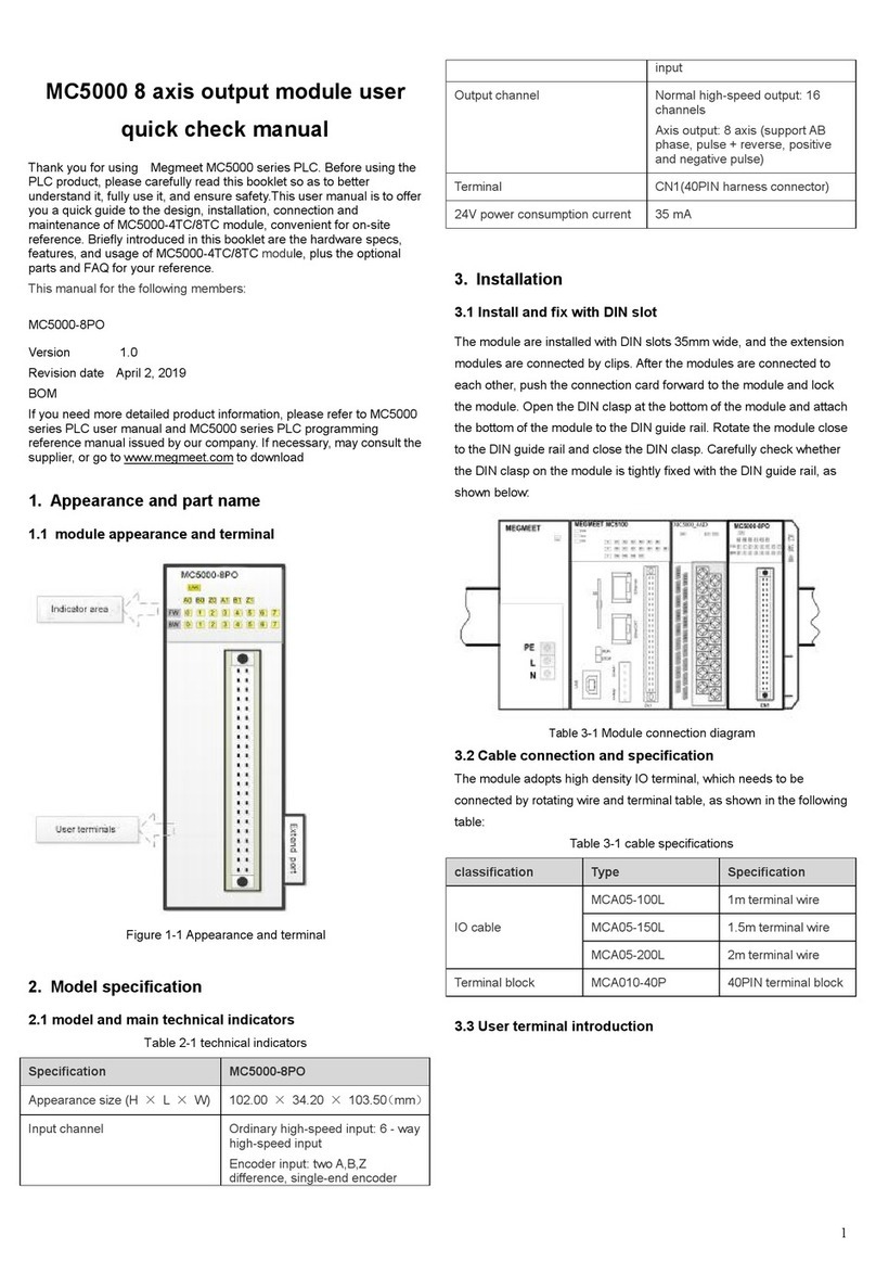
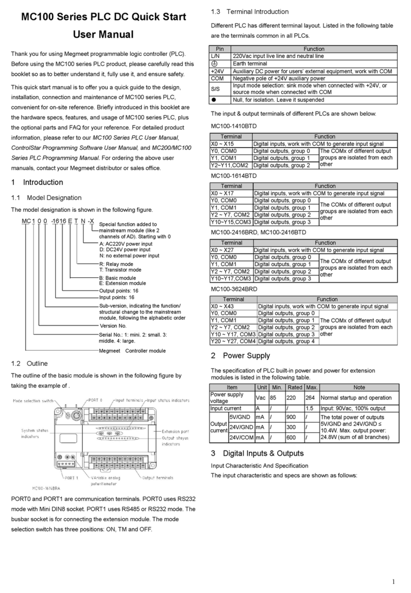
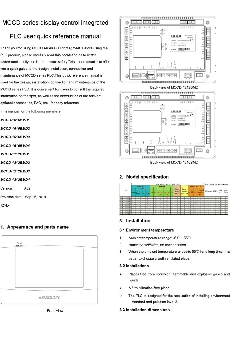
Megmeet MV820 User manual

1
MV820 High-Performance Vector Control Drive
User Manual
Document Version: V2.0
Archive Date: 2024/01/24
BOM Code
Shenzhen Megmeet Electrical Co., Ltd. provides professional technical support for our
customers. You can contact the local branch office or customer service center, or
directly contact the company headquarters.
Shenzhen Megmeet Electrical Co., Ltd.
All rights reserved. The contents in this document are subject to change without
notice.
Shenzhen Megmeet Electrical Co., Ltd.
Address: 5th Floor, Block B, Unisplendor Information Harbor, Langshan Road, Nanshan
District, Shenzhen, 518057, China
Zip code: 518057
Website: https://www.megmeet.com/
Tel: +86-755-86600500
Fax: +86-755-86600562

2
Foreword
Thank you for choosing Megmeet MV820 series high-performance vector control drive.
As a new-generation vector control platform, MV820 adopts an advanced drive solution, which integrates synchronous
motor drive and asynchronous motor drive, torque control and speed control, and possesses leading drive indicators,
able to meet various needs that require high performance. Meanwhile, MV820 has sound anti-trip control and strong
adaptation to harsh environments with bad power mains, high temperature, high humidity or filled with dust, largely
improving the reliability.
MV820 provides modular expansion, enabling you to add modules flexibly based on your special needs. Besides, MV820
has advanced VF, SVC and FVC for speed and torque control, closed-loop process control, multi-function input and
output terminals, pulse frequency reference, simple PLC, main/auxiliary reference control, master-slave control and so
on, fully capable for various drive scenarios, lowering system costs and improving system reliability.
MV820 is designed with overall electromagnetic compatibility and optimized PWM control, meeting environmental
requirements for low noise and low electromagnetic interference.
This manual mainly consists of installation, wiring, parameter setting, fault diagnosis, trouble shooting, daily
maintenance and related matters. Please read this manual carefully before you install and use the drive so as to release
the drive’s full potential, keep the manual properly and give it to the actual user when necessary.
Unboxing inspection
When you unbox the product, remember to check the following:
whether there is any damage;
whether the rated values on the nameplate are the same as what you ordered.
Our company has implemented strict inspection on the product’s manufacturing and packaging. If there is still any error,
please contact us or the local distributor.
We are engaged in the continuous improvement of drives. The relevant manuals provided by us are subject to change
without notice.

3
Safety precautions
Indicates that failure to comply with the notice can result in death or severe personal injuries.
Indicates that failure to comply with the notice may result in moderate or minor personal injuries
or equipment damage.
Install the product on incombustible materials such as metal. Failure to comply will result in a fire.
Do not install the product near combustible objects. Failure to comply will result in a fire.
Do not install the product in places with explosive gases.
The wiring work must be done by professional personnel. Otherwise, there will be an electric shock.
Before wiring, check that the input power supply is cut off. Otherwise, there will be an electric shock.
Properly connect the grounding terminal of the drive. Otherwise, there will be an electric shock.
Properly close the cover before power-on. Otherwise, electric shock or explosion may occur.
When powering on a drive that has been stored for 2 years, use a voltage regulator to increase voltage gradually.
Otherwise, electric shock or explosion may occur.
To avoid electric shock, do not touch terminals when the drive is powered on.
To avoid electric shock, do not operate the drive with wet hands.
Before conducting maintenance, ensure that the power is cut off for 10 minutes, and check that the charging
indicator is completely off or the voltage of bus negative/positive is below 36 V. Failure to comply will result in an
electric shock.
Only professional personnel is qualified to replace the components. Do not leave any wire or metal parts inside the
drive. Failure to comply will result in a fire.
After changing the control board, you need to properly set the parameters before running. Otherwise, there will be
equipment damage.
The bare parts of the terminal lugs in the main circuit must be wrapped with insulation tape. Otherwise, electric
shock may occur.

4
When carrying the drive, protect the operating panel and the cover against any stress. Failure to comply will result
in personal injuries or equipment damage.
Install the product on the place that can bear the weight. Failure to comply will result in personal injuries or
equipment damage.
Do not install the drive near water pipes or other places with water splash. Otherwise, there will be equipment
damage.
Take care not to drop screws, gaskets, metal bars and the like into the drive. Otherwise, fire and equipment
damage may occur.
If the drive is damaged or lack of components, do not run the drive. Failure to comply will result in a fire or personal
injuries.
Do not install the product in the place exposed to direct sunlight. Otherwise, there will be equipment damage.
Do not short terminal + and (-). Otherwise, fire and equipment damage may occur.
Cable lugs must be firmly connected to main circuit terminals. Otherwise, there will be equipment damage.
Do not connect 220 V AC input to control terminals other than RA, RB and RC. Otherwise, there will be equipment
damage.

5
Contents
Chapter 1 Introduction of MV820 Series ............................................................9
1.1 Product model.................................................................................................................9
1.2 Product nameplate........................................................................................................9
1.3 Product series............................................................................................................... 10
1.4 Technical specifications..............................................................................................10
1.5 Product components................................................................................................... 14
1.6 Product dimensions..................................................................................................... 14
1.7 Operating panel dimensions...................................................................................... 17
Chapter 2 Options and Accessories..................................................................19
2.1 Accessory cards/options.............................................................................................19
2.1.1 Installation of accessory cards/options............................................................19
2.1.2 MV810-PNET01: PROFINET communication option........................................24
2.1.3 MV810-ECAT01: EtherCAT communication option........................................ 27
2.1.4 MV810-ECAT02: EtherCAT communication option........................................ 31
2.1.5 MV810-IO01: simple IO option...........................................................................35
2.1.6 MV810-PG01: simple incremental ABZ encoder card ................................... 36
2.2 Other accessories....................................................................................................... 38
2.2.1 Dustproof kit........................................................................................................38
2.2.2 Embedded mounting bracket kit.....................................................................38
2.2.3 Reinforced metal bottom plate....................................................................... 40
2.2.4 Wire fixation bracket .........................................................................................40
2.2.5 Guide rail bracket ...............................................................................................40
2.2.6 Keypad/Operating panel mounting base ....................................................... 41
2.2.7 Remote LED keypad/operating panel (with shuttle)................................... 42
2.2.8 Remote LCD keypad/operating panel (in development)............................ 43
2.2.9 Braking unit (see Appendix 2)......................................................................... 43
Chapter 3 Drive Installation ............................................................................... 44
3.1 Assembly/Disassembly of drive components.........................................................44
3.2 Installation environment........................................................................................... 45

6
3.3 Installation direction and gap...................................................................................45
Chapter 4 Drive Wiring ........................................................................................47
4.1 Main circuit terminal wiring and description.......................................................... 50
4.1.1 Main circuit input and output terminal types.................................................50
4.1.2 Connection of drive and accessories.............................................................. 53
4.1.3 Basic operation wiring....................................................................................... 57
4.2 Control circuit terminal wiring and description..................................................... 58
4.2.1 Control circuit terminal layout..........................................................................58
4.2.2 Control circuit terminal wiring......................................................................... 58
4.2.3 Drawing of control board..................................................................................71
4.3 Installation instructions for EMC requirements..................................................... 72
4.3.1 Noise suppression...............................................................................................72
4.3.2 Field wiring requirements.................................................................................74
4.3.3 Grounding............................................................................................................76
4.3.4 Installation of relay, contactor and electromagnetic brake .......................77
4.3.5 Leakage current and measures...................................................................... 78
4.3.6 Proper EMC installation of drive ......................................................................79
4.3.7 Operating instructions for power filter.......................................................... 82
4.3.8 Drive radiation emission................................................................................... 82
Chapter 5 Quick Operation Guide for Drive....................................................84
5.1 Operating panel...........................................................................................................84
5.1.1 Introduction.......................................................................................................... 84
5.1.2 Identification of LED display symbols............................................................. 88
5.1.3 Basic operations................................................................................................. 89
5.2 Operation mode..........................................................................................................92
5.2.1 Operation command channel...........................................................................92
5.2.2 Operation status................................................................................................ 93
5.2.3 Control mode and operation mode................................................................ 93
5.2.4 Drive frequency and torque channel............................................................. 94
5.3 Initial power-on........................................................................................................... 95
5.3.1 Inspection before power-on............................................................................. 95
5.3.2 Initial power-on operation................................................................................96
Chapter 6 Parameter List................................................................................... 97

7
6.1 Explanation of terms related to function codes.................................................... 97
6.2 Function codes of basic menu................................................................................. 97
Chapter 7 Parameter Description.................................................................... 181
7.1 P00: System management parameters..................................................................181
7.2 P01: Status display parameters.............................................................................. 184
7.3 P02: Basic function parameters............................................................................. 189
7.4 P03: Motor 1 parameters......................................................................................... 195
7.5 P04: Motor 1 encoder parameters..........................................................................198
7.6 P05: Motor 1 vector control parameters...............................................................200
7.7 P06: Motor 1 torque control parameters.............................................................. 205
7.8 P07: Motor 1 V/F control parameters....................................................................208
7.9 P08: Startup/Stop control parameters...................................................................211
7.10 P09: Terminal input parameters........................................................................... 216
7.11 P10: Terminal output parameters......................................................................... 230
7.12 P11: Auxiliary function parameters.......................................................................235
7.13 P12: Control optimization parameters.................................................................242
7.14 P13: Multi-speed and simple PLC parameters................................................... 242
7.15 P14: Process PID parameters................................................................................ 249
7.16 P15: Communication parameters.........................................................................255
7.17 P16: Keypad display setting parameters............................................................ 257
7.18 P20: Motor 2 parameters...................................................................................... 259
7.19 P21: Motor 2 encoder parameters........................................................................ 261
7.20 P22: Motor 2 vector control parameters............................................................262
7.21 P23: Motor 2 torque control parameters............................................................262
7.22 P24: Motor 2 V/F control parameters.................................................................263
7.23 P40: Fieldbus option parameters........................................................................ 265
7.24 P41: IO option parameters .................................................................................... 265
7.25 P43: PROFINET communication parameters..................................................... 267
7.26 P50: Option status parameters........................................................................... 269
7.27 P97: Fault and protection parameters............................................................... 270
7.28 P98: Drive parameters.......................................................................................... 276
Chapter 8 Troubleshooting.............................................................................. 278
8.1 List of fault codes..................................................................................................... 278

8
8.2 List of operation exceptions...................................................................................284
Chapter 9 Maintenance....................................................................................287
9.1 Daily inspection......................................................................................................... 287
9.2 Periodical maintenance...........................................................................................288
9.3 Replacing wearing parts......................................................................................... 289
9.4 Storage of drive........................................................................................................290
Chapter 10 Application of Special Functions.................................................291
10.1 Closed-loop application...........................................................................................291
10.2 Integrated communication application...............................................................292
Appendix 1 Modbus Communication Protocol............................................. 295
Appendix 2 Braking Components....................................................................314
Appendix 3 Warranty and Service ..................................................................318
Parameter recording table ...............................................................................320
Wiring Diagram.................................................................................................. 322

9
Chapter 1 Introduction of MV820 Series
1.1 Product model
The drive model on the nameplate indicates the product series, voltage class, power rating, product version and so on.
1.2 Product nameplate

10
1.3 Product series
Table 1-1 Drive series
Enclosure
model
Drive model
Rated input
current
(A)
Rated output
current
(A)
Rated output
power
(kW)
Fan’s air volume
(m³/min)
B
MV820G1-2S0.4B
5.3
2.4
0.4
0.4
MV820G1-2S0.75B
10.4
4.2
0.75
MV820G1-2S1.5B
16.2
7.5
1.5
MV820G1-2S2.2B
23.0
9.4
2.2
0.48
MV820G1-2D0.4B
5.3/4.1
2.4
0.4
0.4
MV820G1-2D0.75B
10.4/7.5
4.2
0.75
MV820G1-2D1.5B
14.0/9.0
7.0
1.5
MV820G1-2D2.2B
23.0
9.4
2.2
0.48
MV820G1-4T0.4B
2.4
1.5
0.4
0.4
MV820G1-4T0.75B
3.5
2.7
0.75
MV820G1-4T1.5B
5.1
4.2
1.5
MV820G1-2T2.2B
11.4
9.4
2.2
0.48
MV820G1-4T2.2B
5.8
5.6
2.2
MV820G1-4T3.7B
10.5
9.4
3.7
C
MV820G1-2T3.7B
21.3
17.0
3.7
0.80
MV820G1-4T5.5B
14.5
13.0
5.5
MV820G1-4T7.5B
20.5
17.0
7.5
D
MV820G1-2T5.5B
32.0
25.0
5.5
1.8
MV820G1-2T7.5B
41.0
32.0
7.5
MV820G1-4T11B
26.0
25.0
11.0
MV820G1-4T15B
35.0
32.0
15.0
E
MV820G1-4T18.5B
49.0
37.0
18.5
4.0
MV820G1-4T22B
58.0
45.0
22.0
F
MV820G1-4T30B
62.0
60.0
30.0
5.8
MV820G1-4T37B
76.0
75.0
37.0
1.4 Technical specifications
Table 1-2 Technical specifications
Input
Rated voltage
(V)
2S/2D/2T models: single/three-phase 220 V to 240 V; continuous fluctuation of voltage
±10%, transient fluctuation -15% to +10%, that is, 187 V to 264 V; voltage unbalance
rate: < 3%, distortion rate compliant with IEC 61800-2
4T models: three-phase 380 V to 480 V; continuous fluctuation of voltage ±10%,
transient fluctuation -15% to +10%, that is, 323 V to 528 V; voltage unbalance rate: <
3%, distortion rate compliant with IEC 61800-2

11
Rated input
current (A)
Refer to Table 1-1.
Rated
frequency (Hz)
50 Hz/60 Hz, fluctuation range: ±2 Hz
Output
Rated output
power (kW)
Refer to Table 1-1.
Rated output
current (A)
Output voltage
(V)
Three-phase output under rated input conditions, 0 to rated input voltage, deviation
less than ±3%
Output
frequency (Hz)
V/F: 0.00 to 599.00 Hz (unit: 0.01 Hz); vector control: 0.00 to 599.00 Hz
Overload
capacity
1 min for 150% rated current
3 s for 180% rated current
1 s for 200% rated current
Drive control
Control mode
Flux vector control without PG, V/F control, Flux vector control with PG
Maximum
output
frequency
V/F control: 599 Hz, other control methods: 599 Hz; high-frequency version: 3500 Hz
Speed
regulation
range
1: 200 (flux vector control without PG); 1: 1000 (flux vector control with PG)
Speed control
precision
±0.5% (flux vector control without PG); ±0.02% (flux vector control with PG)
Speed
fluctuation
±0.3% (flux vector control without PG); ±0.1% (flux vector control with PG)
Torque
response
< 20 ms (flux vector control without PG); < 10 ms (flux vector control with PG)
Torque control
Torque control precision ±5% for vector control without PG (above 5 Hz for
asynchronous motors, above 10 Hz for synchronous motors); ±3% for vector control
with PG

12
Startup torque
0.25 Hz 150% (flux vector control without PG); 0.00 Hz 180% (flux vector control with
PG)
Product
functions
Key functions
Fast tracking, over-torque/under-torque detection, torque limit, multi-speed reference,
multiple acceleration/deceleration time switchover, auto-tuning, S curve
acceleration/deceleration, slip compensation, fan speed control, frequency hopping,
energy saving operation, PID adjustment, sleep function, power dip ride-through,
Modbus, torque control, torque control and speed control switchover, automatic
restart, DC braking, dynamic braking; simple PLC, AVR, 2 sets of motor parameters
switchover, fieldbus communication; master-slave control and so on.
Basic
frequency
0.01 Hz to 599.00 Hz
Startup
frequency
0.00 Hz to 50.00 Hz
Frequency
setting mode
Digital panel setting, analog reference: AI1/AI2, terminal pulse HDI setting; simple PLC
reference, multiple PLC reference, host controller communication setting, PID control
reference and fieldbus communication setting
Acceleration/
Deceleration
time
0.1 to 6000.0 (unit: 0.1 s)
Dynamic
braking
capacity
Built-in braking units for the whole MV820 series, braking ratio 0.0 to 100.0%
DC braking
capacity
Startup frequency: 0.00 Hz to 599.00 Hz; braking time: 0.1 s to 50.0 s
Braking current: 0% to 100%, according to the nominal rated current of the drive
Terminal
functions
Refer to the terminal function part for details.
Protection
function
Refer to the fault protection part for details.
Others
Efficiency
≧93% (7.5 kW or below); ≧95% (15 kW or below)
Installation
method
Wall-mounted: vertically mounted on a solid base indoors, with at least 100 mm space
for air inlet and outlet, and at least 10 mm left for both the left side and the right side
(excluding enclosure A/B), air cooling.
Protection
degree
IP20

13
Cooling
method
Air cooling
Environment
Operating site
Indoors without direct sunlight, dust, corrosive gas, combustible gas, oil mist, water
vapour, drip or salt
Altitude
≤1000 m: derating not required; 1000 m < altitude < 3000 m: derated by 1% for every
additional 100 m; maximum altitude: 3000 m
Ambient
temperature
-10℃ to +50℃, air temperature change < 0.5℃/min (derating required if the ambient
temperature is above 40℃)
Humidity
5% to 95% RH, non-condensing, no rain, snow and hail, solar radiation < 700 W/m2,air
pressure 70 to 106 kPa
Vibration
Sine vibration: 2 to 9 Hz, displacement 1.5 mm; 9 to 200 Hz, 5.9 m/s2(0.6 g)
Storage
temperature
-30℃ to +70℃, air temperature change < 1℃/min.
Maximum 60℃ for long-time storage, 60℃ to 70℃ only for short-time storage.

14
1.5 Product components
1
23
5
89
11
10
12
6
4
7
1: Enclosure 2: Encoder board 3: Control box 4: Keypad 5: Expansion box 6: Rubber plug
7: Upper cover 8: Wire fixation bracket 9: Grounding board 10: Fan cover 11: Fan 12: Dustproof plate
Fig. 1-1 Part of components (taking enclosure B as an example)
1.6 Product dimensions
There are five types of outline dimensions as shown in Fig. 1-2, Fig. 1-3, Fig. 1-4, Fig. 1-5 and Fig. 1-6. The specific outline
dimensions, mounting dimensions and gross weight are shown in Table. 1-3. The drawings are only for illustration. For
details, check your actual products.
(1) Enclosure B: 2S0.4 kW to 2.2 kW
2D0.4 kW to 2.2 kW
4T0.4 kW to 4T3.7 kW
2T2.2 kW
Fig. 1-2 Enclosure B

15
(2) Enclosure C: 2T3.7 kW; 4T5.5 kW / 7.5 kW
Fig. 1-3 Enclosure C
(3) Enclosure D: 2T5.5/7.5 kW; 4T11/15 kW
Fig. 1-4 Enclosure D

16
(4) Enclosure E: 4T18.5/22 kW
Fig. 1-5 Enclosure E
(5) Enclosure F: 4T30/37kW
Fig. 1-6 Enclosure F
Table 1-3 Outline, mounting dimensions and gross weight
Enclosure
model
Drive model
A (mm)
B1 (mm)
B2 (mm)
H (mm)
W (mm)
D
(mm)
Mounting
hole
diameter
(mm)
Gross
weight±
0.5 (kg)

17
Enclosure
model
Drive model
A (mm)
B1 (mm)
B2 (mm)
H (mm)
W (mm)
D
(mm)
Mounting
hole
diameter
(mm)
Gross
weight±
0.5 (kg)
Enclosure B
MV820G1-2S0.4B
187.5
50
61
200
72
158.5
4.5
1.4
MV820G1-2S0.75B
MV820G1-2S1.5B
MV820G1-2S2.2B
MV820G1-2D0.4B
MV820G1-2D0.75B
MV820G1-2D1.5B
MV820G1-2D2.2B
MV820G1-4T0.4B
MV820G1-4T0.75B
MV820G1-4T1.5B
MV820G1-2T2.2B
MV820G1-4T2.2B
MV820G1-4T3.7B
Enclosure C
MV820G1-2T3.7B
259
97.5
97.5
267
115
171
5
2.5
MV820G1-4T5.5B
MV820G1-4T7.5B
Enclosure D
MV820G1-2T5.5B
290
118
118
300
138
195.92
6
4.1
MV820G1-2T7.5B
MV820G1-4T11B
MV820G1-4T15B
Enclosure E
MV820G1-4T18.5B
318
140
140
330
158
204.8
6
-
MV820G1-4T22B
Enclosure F
MV820G1-4T30B
412
196
196
424
220
229
7
15
MV820G1-4T37B
1.7 Operating panel dimensions

18
Fig. 1-7 Appearance and mounting dimensions of operating panel
(1) A removable LED keypad (with a shuttle button) is the standard configuration for the whole MV820 series, which
supports external use. If you want to add a remote LCD keypad, refer to 2.2.8.
(2) An RJ45 port is reserved for an external keypad.

19
Chapter 2 Options and Accessories
The options and accessories introduced in this chapter, including accessory cards, bus options, IO options and others,
are optional. You can purchase them by yourself or consult the local distributor according to your needs. During
installation and use, follow the corresponding steps to avoid damage to the drive.
To clarify, the options in this manual refer to PN, DP and the like with an expansion box (refer to 1.5 Fig. 1-1) while the
accessory cards refer to independent PCBA boards without an expansion box, such as encoder cards.
2.1 Accessory cards/options
The entire MV820 series supports a wide range of expansions, such as PROFINET, EtherCAT, CANopen, PROFIBUS and
other bus expansions, I/O and encoder expansions, capable for scenarios requiring excellent control performance and
multi-unit network.
The options and accessories introduced in this chapter are optional. You can purchase them by yourself or consult the
local distributor according to your needs. During installation and use, follow the below steps to avoid damage to the
drive.
2.1.1 Installation of accessory cards/options
2.1.1.1 Installation position
MV820 provides two positions for accessory cards and options,
as shown in Fig. 2-1 position 1 and position 2 (taking enclosure B as an
example, similar for other enclosures), where position 1 is for the
installation of various PG cards and position 2 is for the installation of
various bus options, I/O options, and so on.
Fig. 2-1

20
2.1.1.2 Installation interfaces
The electrical interfaces of accessory cards/options connected to the drive are shown in Fig. 2-2.
Fig. 2-2 Electrical interfaces
Table of contents
Other Megmeet Controllers manuals

Megmeet
Megmeet MC5000 Series User manual

Megmeet
Megmeet MC100 Series User manual

Megmeet
Megmeet MC5000 Series User manual

Megmeet
Megmeet MC5000 Series User manual

Megmeet
Megmeet MC200E Series Manual

Megmeet
Megmeet MCCD Series Service manual

Megmeet
Megmeet L6 Series User manual

Megmeet
Megmeet MC160 PLC Series User manual
Popular Controllers manuals by other brands

Emerson
Emerson Site Supervisor Quick setup guide

Ibiza
Ibiza LC806S manual

Flowserve
Flowserve Centura DBL Series Installation, operating, & maintenance instructions

Kantech
Kantech KT-NCC Quick configuration guide

Johnson Controls
Johnson Controls TEC3000 Series quick start guide

HIMA
HIMA HIMatrix F2 DO 16 01 Product description