Meijer KOOI-REACHFORKS RE2 Technical reference manual

RE2, REN2
TFE2
RE4, RE8
REE2, REEN2
REE4
Instruction and parts manual
Table of contents
Denitions ............................................................................... 2
Note.......................................................................................... 2
Quality Standards/Norms and Directives .......................... 2
Safety....................................................................................... 3
Identication .......................................................................... 4
Assembly................................................................................. 5
Working with KOOI-REACHFORKS® .................................. 6
Maintenance Schedule......................................................... 6
Wear......................................................................................... 7
Instructions for Replacement of Sleeve ............................ 8
Replacement of Hydraulic Parts ......................................... 9
Troubleshooting...................................................................... 11
Replacement parts list RE2, REN2....................................... 13
Replacement parts list RE2 (cont’d).................................... 14
Replacement parts list RE2 (cont’d).................................... 15
Replacement parts list RE2 (cont’d).................................... 16
Replacement parts list TFE2................................................. 17
Replacement parts list RE4................................................... 18
Replacement parts list RE4 (cont’d).................................... 19
Replacement parts list RE4 (cont’d).................................... 20
Replacement parts list RE8................................................... 21
Replacement parts list REE2, REEN2 .................................. 22
Replacement parts list REE4 ................................................ 23
Replacement parts list REE4 (cont’d) ................................. 24
Manual Nº: MA020414-07ENG Language: ENG
Publishing date: 10-05-2019 Revision 07

2
Warning:
Text blocks marked by a “Warning” icon (as shown on the left) and starting with the text “ Warning:” provide
information on actions which may result in serious injury.
Caution:
Text blocks marked by a “Caution” icon (as shown on the left) and starting with the text “Caution:” provide
information on actions which may result in damage to the KOOI-REACHFORKS®, parts of the KOOI-REACH-
FORKS® or goods.
“Only applies to:” texts (italics) indicate that a text only applies to a certain situation or certain type of KOOI-REACH-
FORKS®.
Note
© Copyright 2006 - 2019, Meijer Handling Solutions B.V. All rights reserved.
Unless otherwise indicated, information provided in this manual, including but not limited to illustrations and text, may
not be reproduced without the prior written permission of Meijer Handling Solutions.
The information in this manual is provided without any form of guarantee. Under no circumstances shall Meijer Handling
Solutions B.V. be held liable for accidents or damages arising from the use of this manual.
Please note that information in this manual may be changed at any time without prior notice and that it may contain tech-
nical inaccuracies and typing errors. Meijer Handling Solutions B.V. makes every effort to avoid errors in this manual, but
cannot guarantee this. Please let us know if you encounter any typing errors or technical inaccuracies, or if you have
any suggestions.
KOOI-REACHFORKS® is a registered trademark of Meijer Handling Solutions. (Gebr. Meijer).
Other trade or product names used in this manual, but not mentioned here, are the trademarks of their respective hold-
ers.
Denitions
Quality Standards/Norms and Directives
Meijer Handling Solutions B.V. complies with the following quality standards: ISO 9001
KOOI-REACHFORKS® comply with the following norms/directives:
• ISO 13284 – Fork Arm Extensions and Telescopic Fork Arms;
• ISO 4406 – Hydraulic Fluid Power – Fluids – Method for Coding the Level of Contamination by Solid Particles
• ISO 2328 – Forklift Trucks – Hook-On Type Fork Arms and Fork Arm Carriages
• CE (2006/42/EC) – Machinery Directive
• ISO-FDIS-ISO 3834-2 – Quality Requirements for Fusion Welding of Metallic Materials – Part 2: Comprehensive
Quality Requirements
• CE (2014/43/EG) – ATEX (only applies to forks with an ATEX name plate!)
KOOI-REACHFORKS® are randomly subjected to dynamic testing in accordance with ISO 2330.

3
Safety
Warning:
Do not ride on the KOOI-REACHFORKS® or on
the load.
Warning:
Do no walk or stand under the KOOI-REACH-
FORKS®.
Warning:
Do not reach through the mast of the forklift
truck.
Warning:
Do not load the KOOI-REACHFORKS® beyond
the limits of the lifting capacities and load centre
stipulated by the manufacturer.
Warning:
Do not weld anything onto the KOOI-REACH-
FORKS® without the express permission of the
supplier. Welding carried out without permission
shall void any warranty.
Warning:
Do not use faulty KOOI-REACHFORKS® before
they have been either professionally repaired or
replaced.
Warning:
Do not carry out maintenance work on the
KOOI-REACHFORKS® whilst there is pressure
in the hydraulic system (remove key from forklift
ignition switch).
Warning:
Do not place limbs between pallet stops and the
inner fork (vertical section) of the KOOI-REACH-
FORKS®. If the load shifts, limbs can become
trapped which can result in serious injury.
Warning:
Do not use the KOOI-REACHFORKS® in areas
where the temperature is below -30ºC (-22ºF) un-
less otherwise agreed with the manufacturer.
Caution:
When leaving the forklift the engine must be
switched off and the handbrake applied.
Caution:
Bear in mind the space above and beneath the
KOOI-REACHFORKS®.
Caution:
The load must be distributed as evenly as pos-
sible on the KOOI-REACHFORKS®.
Caution:
Retract the (loaded) KOOI-REACHFORKS® as
soon as possible.
Caution:
If possible, retract the KOOI-REACHFORKS®
before driving.
Caution:
Always drive with the KOOI-REACHFORKS® in
the lowest possible position.

4
Identication
Type plate legend:
Mounting type description of KOOI-REACHFORKS®:
No. of cylinders per set
5
1
2
3
4
5
• Slide the KOOI-REACHFORKS® in and out 10x.
• Tilt the forklift mast back and forth a few times.
• Slide the KOOI-REACHFORKS® in and out 10x
again.
Check that hydraulic hoses are unobstructed and that
there are no oil leakages.
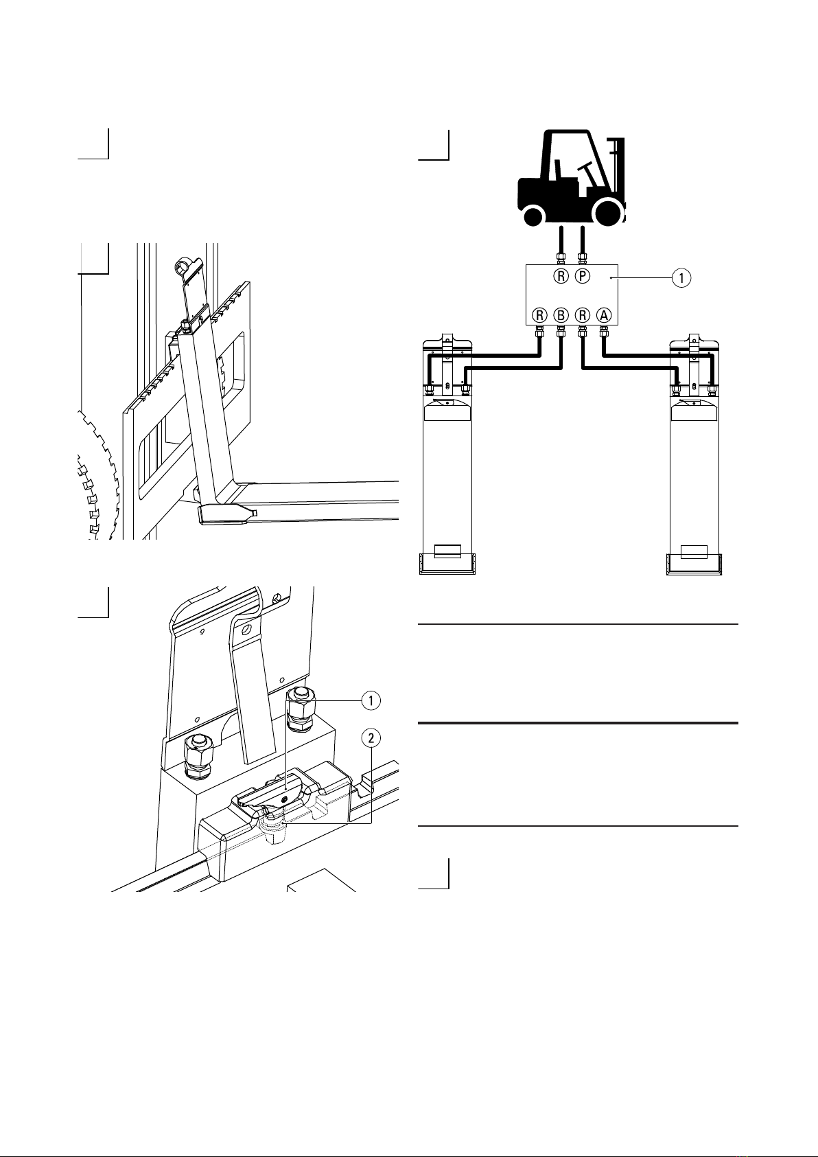
The KOOI-REACHFORKS® type plates are
stamped with an ‘L’ and an ‘R’. Mount the KOOI-
REACHFORKS® on the left (L) and right (R) as
viewed from the forklift operator’s seat.
Assembly
Slide the KOOI-REACHFORKS® onto the carriage plate.
Make sure that each of the KOOI-REACHFORK® lock-
ing pins (2) drops into one of the notches on the carriage
plate. Use catch (1) before operating.
Connect the KOOI-REACHFORKS® to the hydraulic system
via the ow divider (1).
Type KOOI-RE-
ACHFORKS®
Recommended
oil ow
Recommended
hose diameter
Maximum ope-
rating pressure
Connection
All types 8-25 (L/
min)
2.1-6.6
(gal/min)
1/4” 250 bar
(3626
psi)
8L /
7/16”
JIC
(USA)
/ 9/16”
(USA)
6
Working with KOOI-REACHFORKS®
The KOOI-REACHFORKS®, type RE, are connected via a ow divider that enables both forks to slide in and out simulta-
neously. The accuracy of the ow divider allows a maximum length discrepancy of 4% while sliding the KOOI-REACH-
FORKS® in and out.
To minimise wear, avoid allowing the KOOI-REACHFORKS® to come in contact with the ground during operation . In
order to reduce wear:
• The manufacturer can weld a wear-resistant plate under the sleeve which can be replaced when worn out.
• The chains in the forklift mast can be shortened so that the KOOI-REACHFORKS® cannot reach the ground.
Maintenance Schedule
Nº Description Weekly Monthly 6 months or
every 1000
hours
Annually or
every 2000
hours
1. Grease the underside and topside of the
inner fork
2. Check inner fork for leaks
3. Check wear strips for any sign of wear*
4.
Check sleeve for signs of wear, espe-
cially the heel side (REE/REEN type also
wear plate)
5. Check for and remove any dirt in the
sleeve
6. Check for any cylinder head leaks
7. Check inner forks in accordance with
ISO 5057* standards
*See chapter on ‘Wear’.
Notes on ‘Maintenance Schedule’
• Recommended lubricating grease: Nova-
tex EP2 (point 1).
• In the event of leakage, immediately
remove the forks from the forklift and
contact your supplier (point 2).
• If defects are detected, solve the problem
/ replace parts before proceeding to work
with the KOOI-REACHFORKS®.
• See chapter on ‘Instructions for Re-
placement of Sleeve’ and ‘Instructions
for Replacement of Hydraulic Parts’ for
further explanation about replacing parts
and required tools.

7
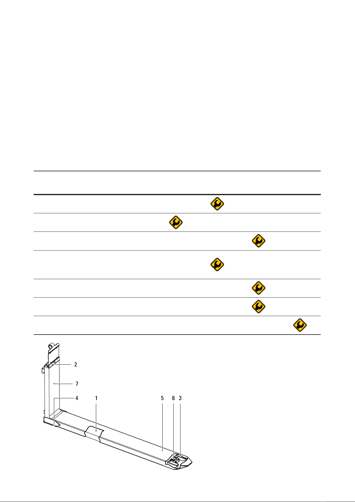
Wear
The thickness of Wear Strips (1) may not be less than
1.5 mm (1/16”). When Wear Strips (1) have worn to this
thickness, replace them or ll with spacers (2) (Art. Nº
RE0092002). See point 3 of the Maintenance Schedule.
The inner fork must be replaced when S1 is 5% thinner
than S2. See point 7 of the Maintenance Schedule.
When surface A (dark grey, integrated wear plate) is
worn to the extent that it is level with or below surface B
(light grey), then the sleeve (1) must be replaced or tted
with a welded-on wear plate. For more information about
welded-on wear plates, please contact your fork supplier.
See point 4 of the Maintenance Schedule.
Caution:
The sleeves must be removed from the KOOI-
REACHFORKS® before welding work can
proceed.
Pistons, piston rods and cylinder heads must
be removed before welding is carried out in the
inner fork.
Applies only to: KOOI-REACHFORKS® type REE and REEN;
When surface A (dark grey, integrated wear plate) is
worn to the extent that it is level with or below surface
B (light grey), then the sleeve (2) must be replaced. If
there are signs of wear in the lower side of the sleeve (2)
then it must be replaced. See point 4 of the Maintenance
Schedule.
Wear Plate Welding Data:
• Process: MAG (135), 210A, 28 VDC
• Weld type: llet weld a4, 1 layer
• Cleaning: brush
• Wire: 1 mm, EN 12534 / Mn3Ni1CrMo
• Shielding gas: 80% Ar / 20% CO2, 15-16 L/min
• Weld in wear-plate grooves
8
1
2
3
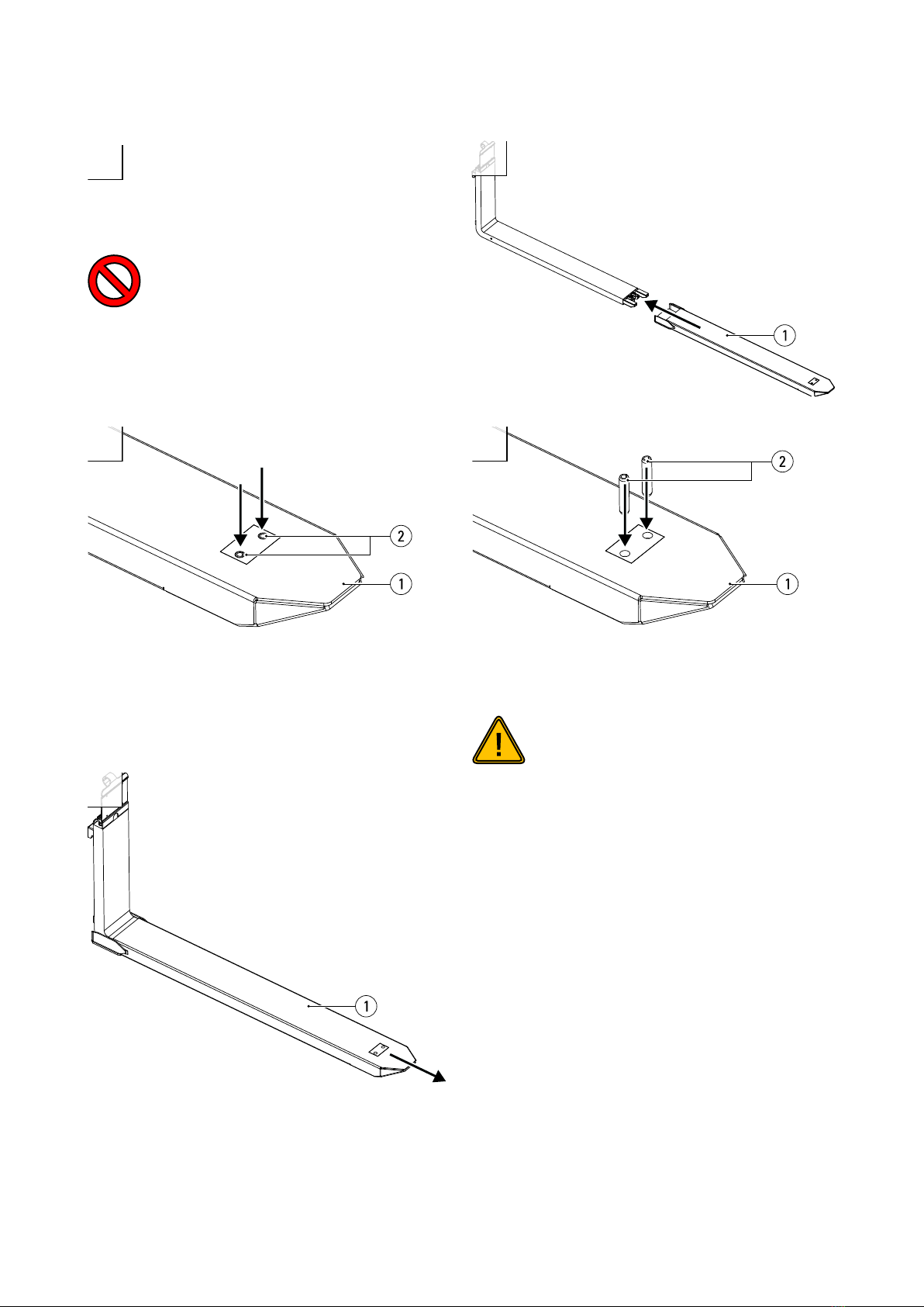
Instructions for Replacement of Sleeve
4
5
Position the KOOI-REACHFORKS® at hip height,
tilt the mast of the forklift slightly forward and
remover the key from the ignition switch of the
forklift.
Warning:
Do not carry out maintenance work on the
KOOI-REACHFORKS® whilst there is pressure
in the hydraulic system (remove key from forklift
ignition switch).
Pull the sleeve (1) off the fork.
Tap the spring pins (2) out of the sleeve (1).
Tools required: Hammer, punch Ø10
Slide the (new) sleeve (1) over the fork.
Tap the spring pin(s) (2) into the (new) sleeve (1).
Caution:
Ensure that the holes in the sleeve (1) are aligned
with the opening in the bracket(s) that are
welded onto the piston rod(s). DO NOT tap the
spring pin onto the bracket or piston rod!
Tools required: Hammer.

9
1
2
3
4
5
Follow steps 1 to 3 in chapter on ‘Instructions for
Replacement of Sleeve’.
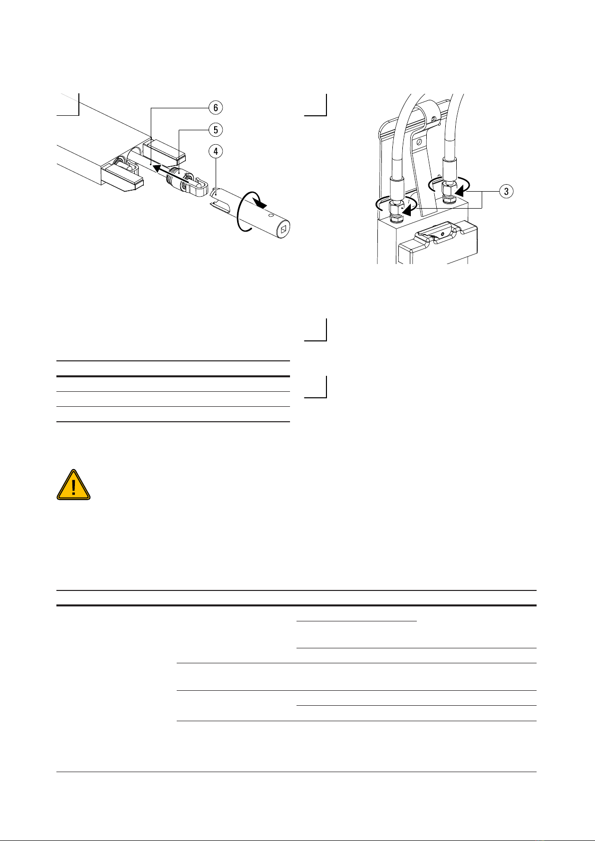
Replacement of Hydraulic Parts
Loosen the hose connectors (3) slightly so that the pistons
do not create a vacuum when removing the hydraulic
parts.
Tools required: Open-ended spanner 17.
Place a drip tray below the fork. Unscrew the cylinder
head(s) (5) using a cylinder head spanner (4) and a
ratchet.
Tools required: Cylinder head spanner, 1/2’’ ratchet.
*Cylinder head spanners are only available from Meijer
Handling Solutions B.V. (Art. Nº RE0058034).
Pull the entire hydraulics set (6) consisting of the piston,
cylinder head and piston rod out of the fork.
Caution:
Take care with the surface of the piston rod.
Even minor damage to surface can cause leaks.
Clamp the piston rod at the rod end (7), not on the piston
rod itself to prevent damage (see step 4 in this chapter).
Use a size 19 or 24 (8) open-ended spanner to loosen the
piston (9). If the piston cannot be loosened, heat the piston
with a burner.
Tools required: Open-ended spanner 19 or 24, clamp.
Note: When heating the piston with a burner, it must be re-
placed due to the damage to the seals caused by heating.
Warning:
Do not use a burner in an area not equipped/in-
tended for his purpose because of re hazard.

10
6
7
8
9
When the piston section 1 (14) has been removed the
piston seal (13) can be replaced if necessary. When piston
section 2 (12) is also removed, the cylinder head (5) can be
removed, should it need to be replaced.
Remove remaining adhesive residue from the piston rod
thread (10), then clean the piston rod and thread (10) using
Loctite 70631.
Tools required: Loctite 70631.
Slide the (new) cylinder head (5) onto the piston rod (10).
Caution:
Do not damage the cylinder head seals (5) during
assembly as this can result in leakage. Pay par-
ticular attention when the sliding cylinder head
(5) over the thread (10) of the piston rod.
Apply Loctite 270 to the thread (10) of the piston rod 1.
Clamp the piston rod at the rod end (7), not on the piston
rod itself to prevent damage (see step 4 in this chapter).
Clean the piston thread with Loctite 70631. Use a torque
wrench 19 or 24 (11) to tighten the piston (9) onto the
piston rod (10) to a torque of 70 Nm.
Tools required: Loctite 2701, Loctite 70631, torque wrench
19 or 24.
11
10 11
12
13
Follow steps 4 to 5 in chapter on ‘Instructions for
Replacement of Sleeve’.
Smear Copaslip2 onto the thread of the cylinder head (5).
Line up the hydraulic set (6) with the cylinder and use a
hammer to tap it carefully into the bore. Screw the cylin-
der head tight using the cylinder head spanner (4) and a
torque wrench. See table below for torque values.
Tools required: Hammer, Copaslip2, cylinder head span-
ner*, 1/2” torque wrench.
*Cylinder head spanners are only available from Meijer
Handling Solutions B.V. (Art. Nº RE0058034).
Caution:
Do not damage the piston or cylinder head seals
during assembly as this can result in leakage.
Screw the hose connectors (3) tight.
Tools required: Open-ended spanner 22.
Finally, follow step 5 of the chapter on
‘Assembly’.
1 See www.loctite.com
2 See www.kroon-oil.com
Troubleshooting
Observation Symptom Possible Cause Possible Solution
Oil leak
Oil leak between cylinder
head and piston rod
Bent piston rod Replace piston rod and
cylinder head
Scratched/damaged piston
rod
Leaking piston seal Replace cylinder head
Oil leak between cylinder
head and fork blade. Leaking O-Ring Replace cylinder head
Oil leak at connector Leaking copper ring Replace copper ring
Loose connector Tighten connector
Forks leaking oil One or both KOOI-REACH-
FORKS® are cracked
Remove KOOI-REACH-
FORKS® from carriage
immediately and contact
supplier.
Cylinder diameter (mm) Torque (Nm)
25 60
30 60
35 80
12
Forks moving unevenly
(more than 4%)
Forks not moving in unison
A piston seal is leaking Replace the piston with the
leaking seal
The hydraulic hoses have
been wrongly connected
Connect the hoses as
indicated in chapter on
‘Assembly’
The length of the piston
rods is unequal
Install piston rods of equal
length
Flow of hydraulic oil is not
between 8-25 L/min
Please contact your sup-
plier.
Dirt in the sleeve(s) Dismantle sleeve and
remove dirt
Flow divider is damaged Replace ow divider
One or both sleeves move
without being operated
The control valve is leaking Inform your forklift supplier.
There is air in the hydraulic
system Bleed the system
A piston seal is leaking Replace the piston with the
leaking seal
One sleeve remains station-
ary during retraction then
suddenly retracts quickly Clamping bush(es) broken Replace the clamping
bush(es)
One of the sleeves fails to
retract
Difference in length be-
tween the sleeves Stroke length difference
Piston rods are not same
length.
Please contact your sup-
plier.
Loose piston
Dismantle outer fork,
remove hydraulic set from
fork and tighten piston (70
Nm)
Difference in height be-
tween forks
One fork point hangs lower
than the other
One of the KOOI-REACH-
FORKS® has been perma-
nently deformed as a result
of overloading.
Remove KOOI-REACH-
FORKS® from carriage
immediately and contact
supplier
One of the KOOI-REACH-
FORKS® is not hanging on
the carriage plate
Hang the KOOI-REACH-
FORK® properly onto the
carriage plate (check lock-
ing mechanism)
Carriage plate is not com-
pletely horizontal
Please do contact your
forklift truck supplier.
The forks do not match
(forks belong to different
sets)
Check serial Nºs.
Wear strips on one KOOI-
REACHFORK® are more
worn than the other Replace wear strips
Excessive play between
fork blade and sleeve
Wear strips worn out
Sleeves worn out Replace sleeves
13
10
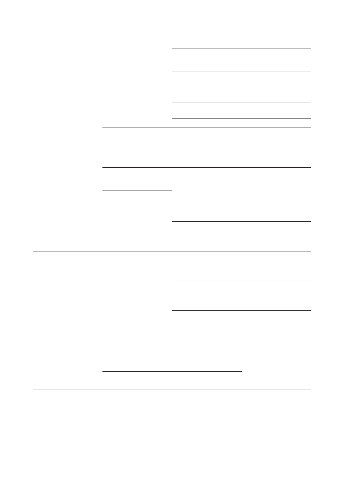
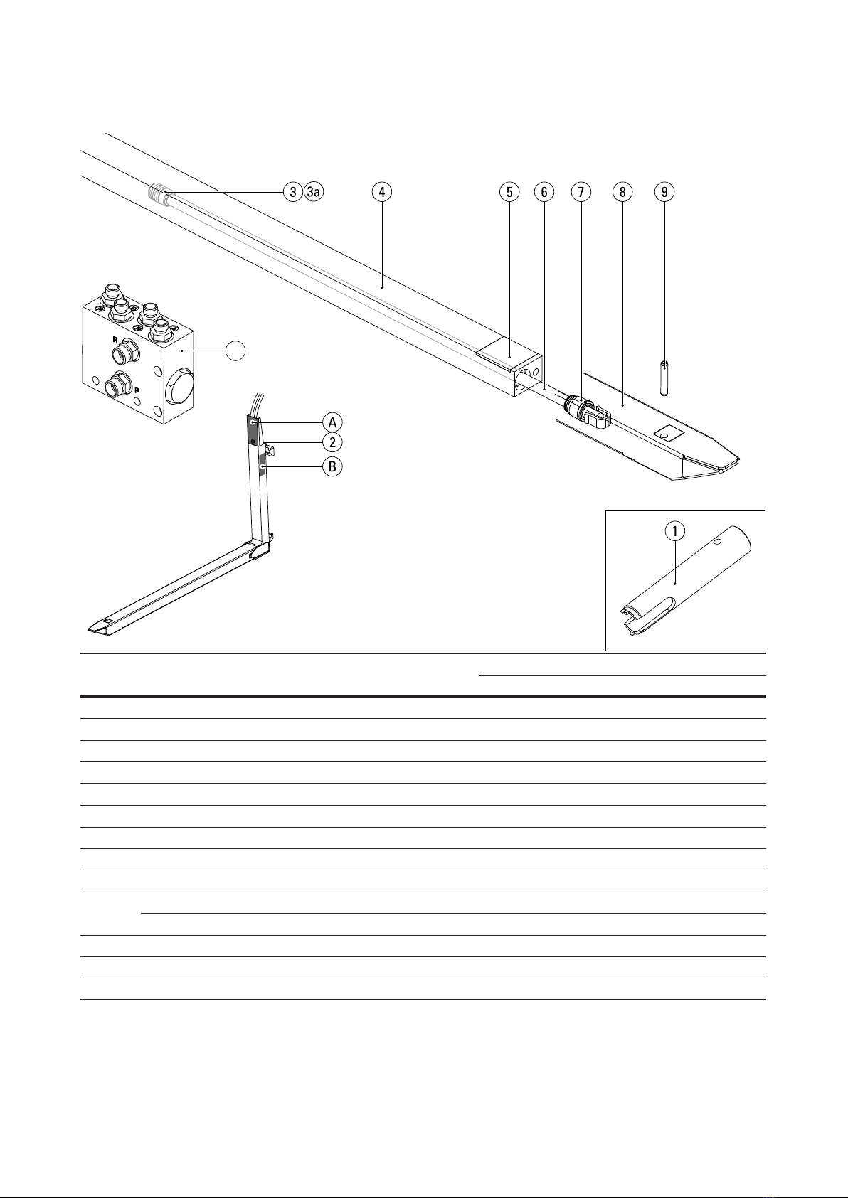
Replacement parts list RE2, REN2
Pos. Nº Description Article Nº Number of parts per set and type of forks
RE2-20 RE2-30 REN2-30 REN2-35
1Cylinder head spanner1RE0058034 - - - -
2Straight male coupling 8L RE2017000 4 4 4 4
3Piston Ø30 (for piston rod Ø20) RE2008001 2 2 2 2
3a Loose piston seal Ø30 RE0015001 2 2 2 2
4Inner fork 22 2 2 2
5Wear strip PA6 RE0020000 4 4 4 4
6Piston rod Ø20 22 2 2 2
7Cylinder Head Ø30 (for piston rod Ø20) RE2009001 2 2 2 2
8Sleeve 22 2 2 2
9Spring pin 55 mm RE0033015 2 2 - -
Spring pin 65 mm RE0033014 - - 2 2
10 Flow divider RE0100000 1 1 1 1
AType plate
B Engraved type information and serial number
1Available separately from KOOI-REACHFORKS® supplier, is not supplied a standard with KOOI-REACHFORKS®.
2Article Nº depending on specic model. Please provide serial number when ordering.
14
10
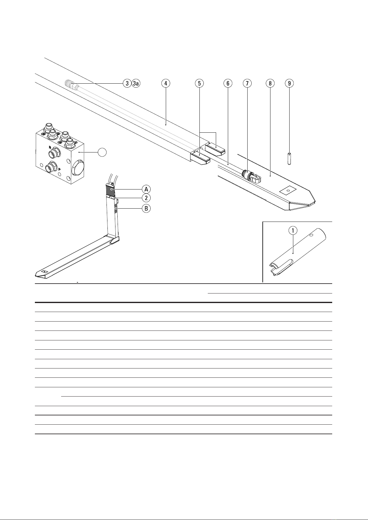
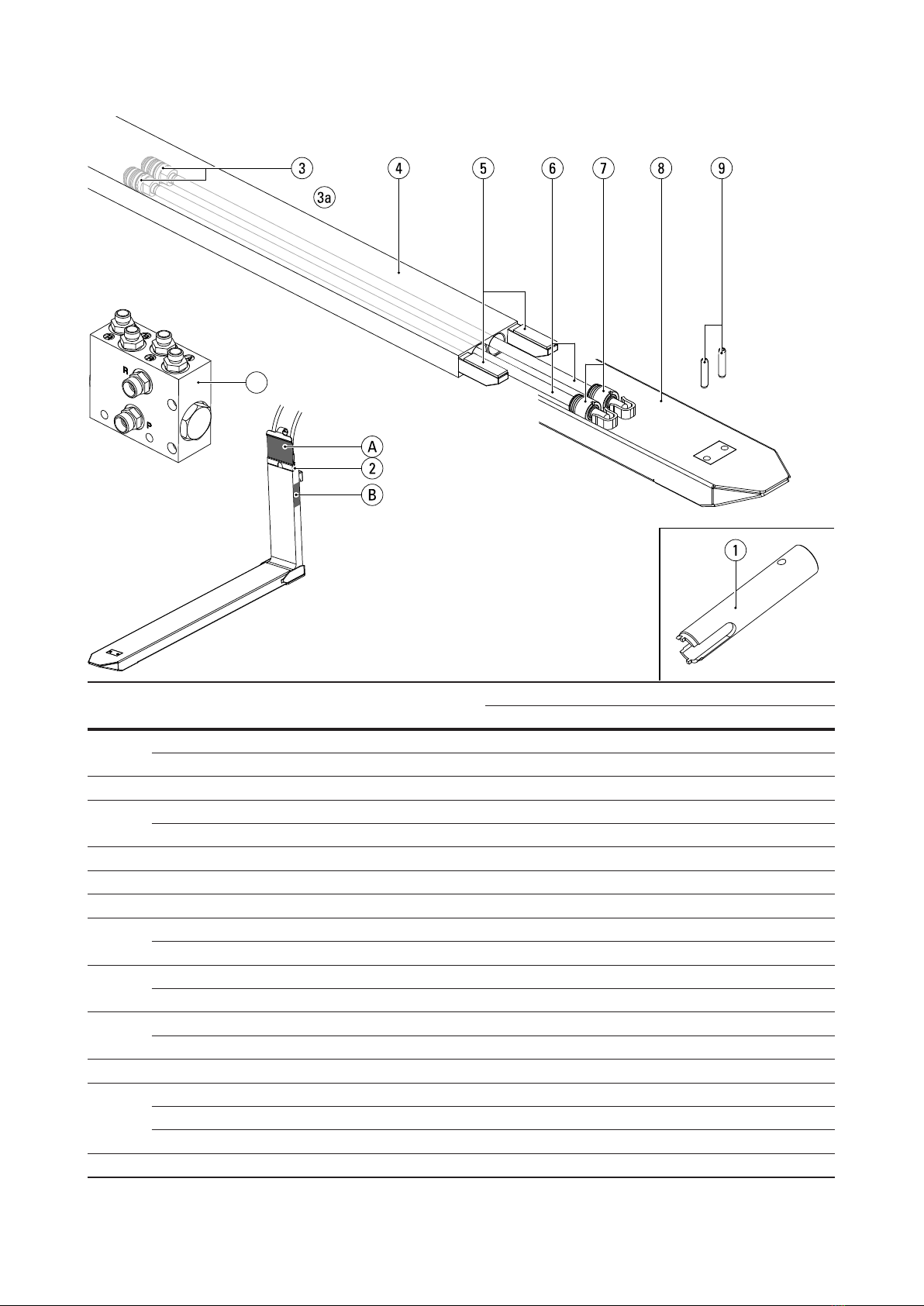
Replacement parts list RE2 (cont’d)
Pos. Nº Description Article Nº Number of parts per set and type of forks
RE2-25 RE2-32 RE2-35 RE2-45 RE2-58
1Cylinder head spanner (Ø30/35)1RE0058034 - - - - -
Cylinder head spanner (Ø25)1RE0058037 - - - - -
2Straight male coupling 8L RE2017000 4 4 4 4 4
3Piston Ø25 (for piston rod Ø16) RE2009000 - 2---
Piston Ø30 (for piston rod Ø20) RE2008001 2-2 2 -
Piston Ø35 (for piston rod Ø20) RE2008004 - - - - 2
3a Separate piston seal Ø25 RE0015000 - 2---
Separate piston seal Ø30 RE0015001 2-2 2 -
Separate piston seal Ø35 RE0015004 - - - - 2
4Inner fork 22 2 2 2 2
5Wear strip PA6 RE0020000 4 4 4 - -
Wear strip AMPCO RE0020001 - - - 4 4
6Piston rod Ø16 2-2---
Piston rod Ø20 22-2 2 2
7Cylinder Head Ø25 (for piston rod Ø16) RE0009000 - 2---
Cylinder Head Ø30 (for piston rod Ø20) RE2009001 2-2 2 -
Cylinder Head Ø35 (for piston rod Ø20) RE2009004 - - - - 2
8Sleeve 22 2 2 2 2
9Spring pin 45 mm 10099293 -2---
Spring pin 55 mm RE0033015 2-2 2 -
Spring pin 65 mm RE0033014 - - - - 2
10 Flow divider RE0100000 1 1 1 1 1
AType plate
B Engraved type information and serial number
1Available separately from KOOI-REACHFORKS® supplier, is not supplied a standard with KOOI-REACHFORKS®.
2Article Nº depending on specic model. Please provide serial number when ordering.
15
10
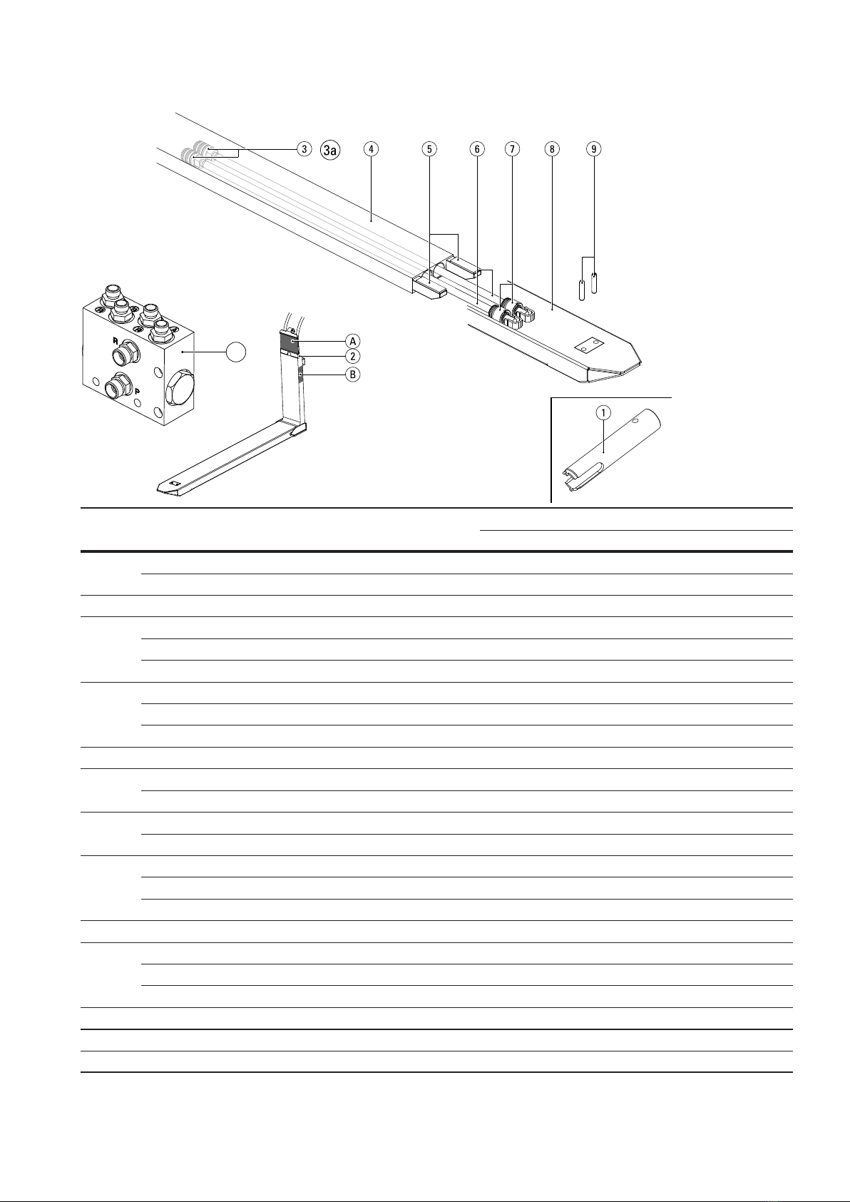
Replacement parts list RE2 (cont’d)
Pos. Nº Description Article Nº Number of parts per set and type of forks
RE2-77 RE2-105
1Cylinder head spanner1RE0058034 - -
2Straight male coupling 8L RE2017000 4 4
3Piston Ø35 (for piston rod Ø20) RE2008004 2 2
3a Separate piston seal Ø35 RE0015004 2 2
4Inner fork 22 2
5Wear strip AMPCO RE0020001 4 4
6Piston rod Ø20 24 4
7Cylinder Head Ø35 (for piston rod Ø20) RE2009004 2 2
8Sleeve 22 2
9Spring pin 65 mm RE0033014 2-
Spring pin 75 mm RE0033023 - 2
10 Flow divider RE0100000 1 1
AType plate
B Engraved type information and serial number
1Available separately from KOOI-REACHFORKS® supplier, is not supplied a standard with KOOI-REACHFORKS®.
2Article Nº depending on specic model. Please provide serial number when ordering.
16
10
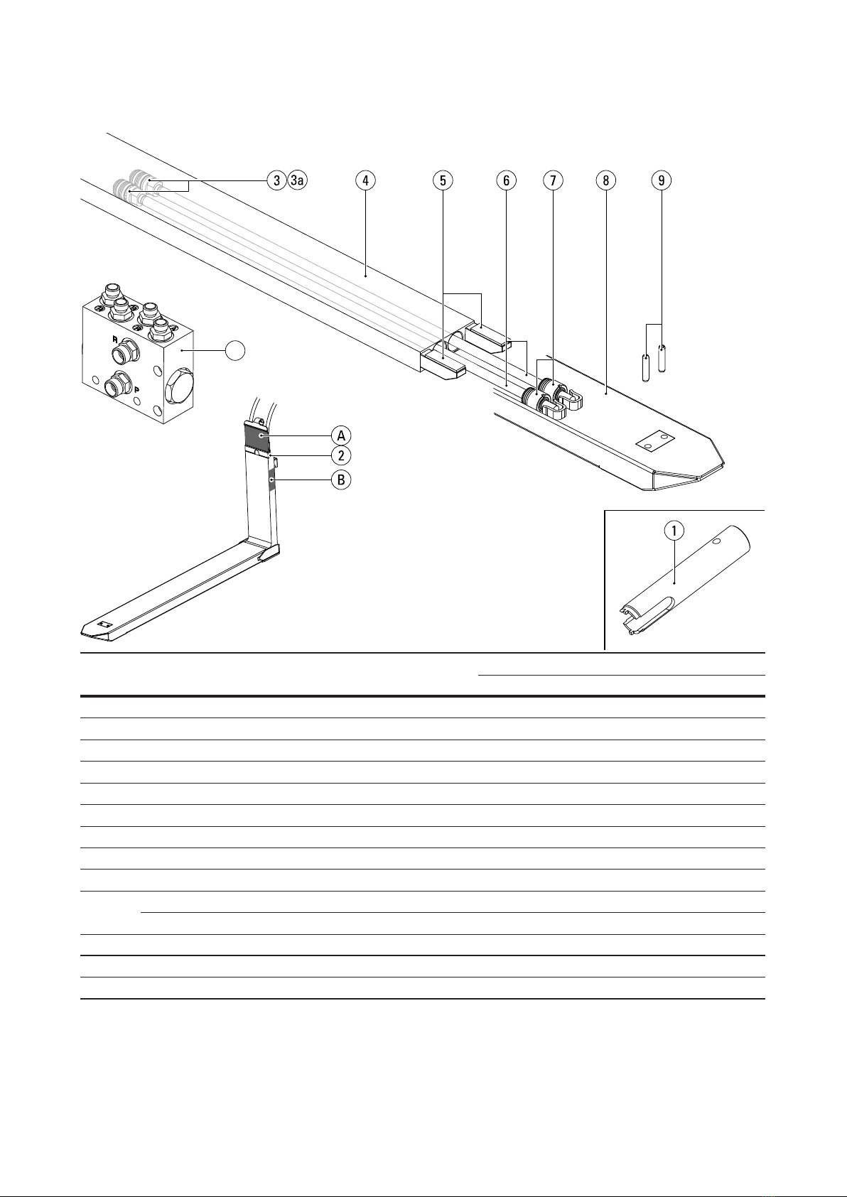
Replacement parts list RE2 (cont’d)
Pos. Nº Description Article Nº Number of parts per set and type of forks
RE2-27 RE2-37
1Cylinder head spanner1RE0058034 - -
2Straight male coupling 8L RE2017000 4 4
3Piston Ø30 (for piston rod Ø20) RE2008001 2 2
3a Separate piston seal Ø30 RE0015001 2 2
4Inner fork 22 2
5Wear strip AMPCO RE0020002 2 2
6Piston rod Ø20 22 2
7Cylinder Head Ø30 (for piston rod Ø20) RE2009001 2 2
8Sleeve 22 2
9Spring pin 65 mm RE0033014 2-
Spring pin 75 mm RE0033023 - 2
10 Flow divider RE0100000 1 1
AType plate
B Engraved type information and serial number
1Available separately from KOOI-REACHFORKS® supplier, is not supplied a standard with KOOI-REACHFORKS®.
2Article Nº depending on specic model. Please provide serial number when ordering.

17
10
Replacement parts list TFE2
Pos. Nº Description Article Nº Number of parts per set and type of forks
TFE2-20
1Cylinder head spanner1RE0058034 -
2Straight male coupling 8L RE2017000 4
3Piston Ø30 (for piston rod Ø20) RE2008001 2
3a Separate piston seal Ø30 RE0015001 2
4Inner fork 22
5Wear strip PA6 RE0020000 4
6Piston rod Ø20 22
7Cylinder Head Ø30 (for piston rod Ø20) RE2009001 2
8Sleeve 21
9Spring pin 65 mm RE0033014 2
10 Flow divider RE0100000 1
AType plate
B Engraved type information and serial number
1Available separately from KOOI-REACHFORKS® supplier, is not supplied a standard with KOOI-REACHFORKS®.
2Article Nº depending on specic model. Please provide serial number when ordering.
18
10
Replacement parts list RE4
Pos. Nº Description Article Nº Number of parts per set and type of forks
RE4-25 RE4-32 RE4-35 RE4-45 RE4-58
1Cylinder head spanner 25 mm1RE0058034 - - - - -
Cylinder head spanner1RE0058037 - - - - -
2Straight male coupling 8L RE2017000 44444
3Piston Ø25 (for piston rod Ø16) RE2008000 43434343-
Piston Ø30 (for piston rod Ø20) RE2008001 - - - 4
3a Separate piston seal Ø25 RE0015000 43434343-
Separate piston seal Ø30 RE0015001 - - - 4
4Inner fork 222222
5Wear strip PA6 RE0020000 4 4 4 - -
Wear strip AMPCO RE0020001 - - 4 4
6Piston rod Ø16 243434343-
Piston rod Ø20 2- - - 4
7Cylinder Head Ø25 (for piston rod Ø16) RE2009000 43434343-
Cylinder Head Ø30 (for piston rod Ø20) RE2009001 - - - 4
8Sleeve 222222
9Spring pin 45 mm 10099293 4
Spring pin 55 mm RE0033015 4 4 4 -
Spring pin 65 mm RE0033014 - - - 4
10 Flow divider RE0100000 11111

19
AType plate
B Engraved type information and serial number
1Available separately from KOOI-REACHFORKS® supplier, is not supplied a standard with KOOI-REACHFORKS®.
2Article Nº depending on specic model. Please provide serial number when ordering.
3 With a stroke of 1200 mm or more, use articles as for type RE4-58
Replacement parts list RE4 (cont’d)

20
10
Replacement parts list RE4 (cont’d)
Pos. Nº Description Article Nº Number of parts per set and type of forks
RE4-77 RE4-105
1Cylinder head spanner1RE0058034 - -
2Straight male coupling 8L RE2017000 4 4
3Piston Ø30 (for piston rod Ø20) RE2008001 4 4
3a Separate piston seal Ø30 RE0015001 4 4
4Inner fork 22 2
5Wear strip AMPCO RE0020001 4 4
6Piston rod Ø20 24 4
7Cylinder Head Ø30 (for piston rod Ø20) RE2009001 4 4
8Sleeve 22 2
9Spring pin 65 mm RE0033014 4-
Spring pin 75 mm RE0033023 - 4
10 Flow divider RE0100000 1 1
AType plate
B Engraved type information and serial number
1Available separately from KOOI-REACHFORKS® supplier, is not supplied a standard with KOOI-REACHFORKS®.
2Article Nº depending on specic model. Please provide serial number when ordering.
This manual suits for next models
7
Table of contents
Other Meijer Forklift manuals


Popular Forklift manuals by other brands


Xtreme
Xtreme XR1555 Operation and safety manual

kleenconnect
kleenconnect LNI2-233 Installation and operation manual

BT
BT SWE100 Repair manual

Xtreme Manufacturing
Xtreme Manufacturing XR1147 Operation and safety manual

Manitou
Manitou MRT-X 2150 Privilege Plus ST3A S2 Operator's manual

logitrans
logitrans ROTATOR ELFR manual


