Oliver 4420 User manual

Planer
Model
4420
Owner’s
Manual
For Models Manufactured Since 05/2019
175370
Oliver Machinery
1-800-559-5065
6902 S 194th St, Kent, WA 98032
WWW.OLIVERMACHINERY.NET
Stock Number: 4420.101
Manual
Version:
2
.0.
0


READ AND UNDERSTAND ALL INSTRUCTIONS IN THIS MANUAL BEFORE
ATTEMPTING TO ASSEMBLE OR OPERATE THE MACHINE.
FOLLOW THE INSTUCTIONS AND THINK SAFETY!
THE OWNER OF THIS MACHINE IS SOLELY RESPONSIBLE FOR THE SAFETY OF ANYONE USING
THIS MACHINE. SUCH RESPONSIBILITY INCLUDES BUT NOT LIMITED TO:
• PROPER ASSEMBLY, OPERATION, INSPECTION, MAINTENANCE, AND RELOCATION OF
THE MACHINE.
• PROPER TRAINING FOR THE OPERATORS AND ENSURES THIS MANUAL IS AVAILABLE
AT ALL TIMES.
• USAGE AUTHORIZATION.
• USAGE OF SAFETY AND PROTECTION DEVICE.
OLIVER MACHINERY DISCLAIMS ANY LIABILITY FOR MACHINES THAT HAVE BEEN ALTERED OR
ABUSED. OLIVER MACHINERY RESERVES THE RIGHT TO EFFECT AT ANY TIME, WITHOUT PRIOR
NOTICE, THOSE ALTERATIONS TO PARTS, FITTINGS, AND ACCESSORY EQUIPMENT WHICH THEY
MAY DEEM NECESSARY FOR ANY REASON WHATSOEVER.
** SAVE THIS MANUAL FOR FUTURE REFERENCES. **
PROP 65 NOTICE
WARNING: Drilling, sawing, sanding or machining wood products can expose you to wood dust,
and/or other chemicals known to the State of California to cause cancer, birth defects or other
reproductive harm.
Some examples of these chemicals are:
• Lead from lead-based paints.
• Crystalline silica from bricks, cement and other masonry products.
• Arsenic and chromium from chemically-treated lumber.
Avoid inhaling wood dust and other harmful chemicals. Use a dust mask and/or other safety
devices for personal protection.
For more information go to http://www.P65Warnings.ca.gov/wood

Table of Contents
Introduction············································· 6
Specifications ·········································· 7
Quick View ·················································7
Product Dimensions····································7
Shipment Info·············································7
Electricals ···················································7
Motor ························································8
Planer Capacity and Performance ···············8
Cutterhead and Headstock ··························8
Measurements ···········································8
Table ··························································9
Safety·························································9
Others ························································9
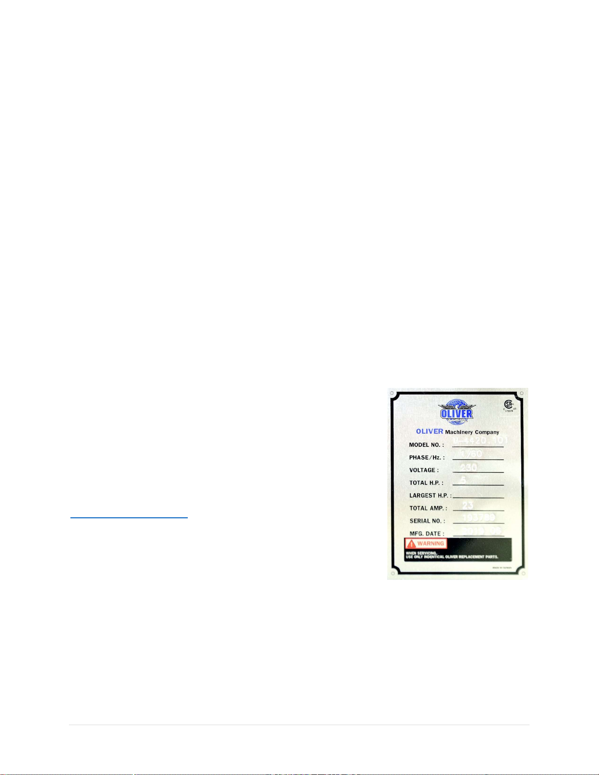
Identification ··········································10
Safety ·····················································12
General Safety Guidelines ························· 12
Safety Guidelines Specific to Planer··········· 13
Electricals ···············································15
Minimum Circuit Size Required for Model
4420 Planer ·············································· 15
Grounding ················································ 15
Electrical Wiring ······································· 15
Setup ······················································17
Shop Preparation······································ 17
Space Requirement ········································· 17
Load Limits ······················································ 17
Electricals ························································ 17
Lighting ···························································· 17
Safety Labels ··················································· 17
Dust Collection ················································ 17
Receiving ·················································· 18
Unboxing ················································· 18
Inventory ················································· 19
Removing Machine from Crate ·················· 20
Cleaning ··················································· 21
Assembly ················································· 21
Installing Height Adjustment Handwheel ······· 22
Installing Dust Hood ········································ 23
Installing Extension Tables ······························ 24
Installing Power Switch ··································· 25
Dust Collection ········································· 26
Wiring and Grounding ······························ 27
Wiring Instructions ·········································· 27
Break-in Period ········································· 27
Controls and Components ······················ 28
ON / OFF Switches ···································· 28
Table Height Adjustment ·························· 28
Table Height Locking Knobs ······················ 28
Table Height Scale ···································· 28
Digital Readout (DRO) ······························· 29
DRO Calibration ··············································· 33
Feed Rate Control ····································· 30
Components for Planing Wood ················· 31
Test Run ··················································· 32
Operation ·············································· 34
Step 1: Preparation ··································· 34
Step 2: Setting Depth of Cut and Feed Rate35
Step 3: Select Feed Direction ····················· 36
Step 4: Planing Wood to Desired Thickness36
Common Cutting Problems ······················· 38
Snipe ································································ 38
Chipping ·························································· 38
Indentation ······················································ 38
Fuzzy Grain ······················································ 38
Accessories ············································ 39
Cutter Inserts ··········································· 39
Touchup Paint ·········································· 39
Maintenance ········································· 40
Maintenance Schedule ····························· 40

Lubrication Schedule ································ 40
Instructions for Maintenance and
Adjustments ············································ 42
Remove Planer Top Cover ······························· 42
Adjust Chip Deflector Clearance ····················· 42
Service Cutterhead and Rotate Cutter Inserts 43
Adjust Belt Tension ········································· 44
Align Belt Pulleys ············································· 45
Adjust Table Chain Tension ····························· 46
Adjust Table Roller Height ······························· 46
Adjust Cutterhead/Feed Roller Height Offset · 47
Adjust Feed Roller Tension ······························ 49
Adjust Cutterhead Height Scale ······················ 50
Anti-Kickback Fingers Inspection····················· 50
Troubleshooting ·····································51
Wiring Diagram ······································54
Parts List ················································ 55
Table Assembly ········································ 55
Motor and Cabinet Assembly ···················· 56
Headstock Assembly ································· 57
Cutterhead and Rollers ····························· 58
Maintenance Record ······························ 66
Notes ····················································· 67
Warranty and Service····························· 68
Appendix ··············································· 69
US Standard – Metric Conversion Chart ····· 69

6 | Page Oliver Machinery 4420 Planer
Introduction
Thank you for choosing Oliver! This manual contains important information on how to safely set up,
operate, and maintain this machine. Please take the time to read through this manual, and make sure you
understand all the instructions.
While this manual may provide tips on optimizing the result of your workpiece, the manual is not intended
as a substitute for formal woodworking training. If you need to know how to safely perform an operation,
please consult knowledgeable and qualified sources before proceeding further.
We made every effort to keep this manual up-to-date. Instructions, specifications, drawings, and
photographs in this manual should match the machine delivered. If you find any differences, or anything
that seems confusing in this manual, or some instructions are not available, please check our website for
an updated version:
WWW.OLIVERMACHINERY.NET/MANUALS
Alternatively, you can contact our Technical Support for help:
1-800-559-5065
Before calling, please note down the manufacture date and serial
number of the machine. You can find the information on a nameplate
located on machine cabinet below the power switch. This information
is needed to provide proper technical support, and to determine if an
updated manual is available for your machine.
Please let us know how well this manual serves you. If you have any
suggestions, please call the number above or email us at:
We love to hear from our customers and make improvements.

4420 Planer OLIVERMACHINERY.NET 7 | Page
Specifications
Quick View
Model
4420 Planer
Stock Number
4420.101
Motor
TEFC Induction Motor
5HP, 230V, 1Ph
Max. Stock Width
16”
Max Depth of Cut
1/8”
(Full width)
15/64"
(
Stock less than
6
-
1/4”
wide
)
Dimensions
44
-
1/4”
(L) x
35
-
1/4”
(W) x
43
-
1/2”
(H)
Footprint
21”
(L) x
24”
(W)
Fully Assembled Weight
568 lbs.
Warranty
1 Year (Motor and electronics)
2 Years (All other parts)
Product Dimensions
Width x Depth x Height (Fully Assembled)
44
-
1/4”
(L) x
35
-
1/4”
(W) x
43
-
1/2”
(H)
Footprint
21”
(L) x
24”
(W)
Fully Assembled Weight
568 lbs.
Shipment Info
Type
Wood Crate with Pallet Base
Content
Planer with Included Accessories
Dimensions
30”
(L) x
35”
(W) x
47”
(H)
Weight
669 lbs.
Approx
imate
Setup
Time
60
minutes
Must Ship Upright
YES
Stackable
NO
Electricals
Power Requirement
230V
,
1Ph
, 60Hz
Full Load Current Rating
23A
Recommended circuit size
30A
Power Switch Type
Magnetic switch with overload protection.
Connection Type
Cord and
plug not included.
Electrical hookups required.
Overload Protection
Equipped

8 | Page Oliver Machinery 4420 Planer
Motor
Motor Type
TEFC Induction Motor
Horsepower
5HP
Speed
3450
RPM
Efficiency
83
%
Power Transfer Mechanism
V
-
belt and pulleys
Bearing type
Permanently
sealed ball bearing
Planer Capacity and Performance
Maximum Stock Width
16”
Maximum Depth of Cut
15/64"
(Stock less than
6
-
1/4”
wide)
1/8”(Full Width)
Maximum Stock Thickness
6”
Minimum Stock Thickness
3/8”
Minimum Stock Length
6”
Feed Rate
16/20 FPM
Number of Cuts Per Square Inch
141
@ 16FPM
113 @ 20FPM
Cutterhead and Headstock
Cutterhead Type
Helical
Cutterhead Diameter
2
-
7
/
8
”
Cutterhead Speed
4800
RPM
Number of Cutter Inserts
90
Number of Rows of Cutter Inserts
5
Cutter Insert Type
Four
-
sided, indexable German made carbide
Cutter Insert Diameters
15mm x 15mm x 2.5mm
Cutter Blade Angle
30 degree
Cutter Insert Screw Tensioning Torque
50
-
55 lbs.
-
inch
Infeed Roller Type
Serrated steel
Outfeed Roller Type
Polyurethane
Table
Height Change Per Each Turn of
Handwheel
Approx.
5/64
” /
2
mm
Stock Return Roller Load Limit
220 lbs.
Measurements
Measurement
Units
Inch/mm
Measurement Devices
Digital Readout (Model
921727-000)
Digital Readout
Resolution
0.0005” / 0.01mm
Digital Readout
Accuracy
±0.001” /
0.03mm
Backup Measurement Device
Standard height scale installed.

4420 Planer OLIVERMACHINERY.NET 9 | Page
Table
Table Dimensions
44
-
1/4
” x
16
”
(With infeed/outfeed table)
19-7/8” x 16”
(Without infeed/outfeed table)
Table Height Above Ground
29
-
1/4
”
-
35”
Table Height Lock
Equipped
Material
Precision ground cast iron
Bed Roller
Two
Extension Table Weight
21 lbs.
Safety
Number of Dust Ports
1
Dust Port Size
4
”
Minimum CFM Required
450 CFM
Sound Rating @ 2’ distance
85 dB
Others
Serial Number Location
On machine cabinet below the power switch.
Spare Parts Included
10 Cutter inserts and compatible torx screws.
Certification
CSA 175370
Country of Origin
Taiwan

10 | Page Oliver Machinery 4420 Planer
Identification

4420 Planer OLIVERMACHINERY.NET 11 | Page

12 | Page Oliver Machinery 4420 Planer
Safety
Oliver Machinery has made every attempt to provide a safe, reliable, easy-to-use piece of machinery.
Safety, however, is ultimately depending on the individual machine operator. Before operating this
machine, please become familiar with the following safety labels and guidelines.
DANGER
This indicate an imminent hazardous situation which, if not avoided,
WILL
cause
death or serious injury.
WARNING This means if the warning is not taken seriously, it CAN cause death or serious injury.
CAUTION This mean if the precaution is not taken, it MAY cause minor or moderate injury.
IMPORTANT This is a tip about proper operation of the machine to avoid machine damage.
General Safety Guidelines
1. FAMILIARIZE yourself with all safety instructions found in this manual. Know the limitations and
hazards associated with this machine. Do not operate / service this machine until you are properly
trained.
2. ELECTRICAL GROUNDING, when done properly, reduce the risk of electrocution, shocks and fire.
Make certain that the machine frame is electrically grounded and that a ground lead is included in the
incoming electrical service. In cases where a cord and a plug are used, make certain that the grounding
plug connects to a suitable ground. Follow the grounding procedure indicated in the electrical code
of your area.
3. DISCONNECT the machine from power before performing any service, maintenance, or adjustments.
A machine under repair should be RED TAGGED to show it should not be used until the repair is
complete.
4. EYE PROTECTION: Always wear an approved safety face shield, goggles, or glasses that complies with
ANSI Z87.1 and CSA Z94.3 standards. Common eyeglasses are not safety glasses, and may not provide
adequate protection.
5. EAR PROTECTION: Use hearing protective devices where the noise exceeds the level of exposure
allowed in Section 1910.95 of the OSHA Regulations. When in doubt, use it.
6. OTHER PERSONAL PROTECTION: Before operating the machine, remove tie, rings, watch and other
jewelry. Roll up sleeves above the elbows. Remove all loose outer clothing and confine long hair.
Protective type footwear should be used. Do not wear gloves unless it is instructed to perform
particular step(s) in the manual.
7. GUARDS: Keep the machine guards in place for all applicable operations. If any guards are removed
for maintenance, DO NOT OPERATE the machine until the guards are reinstalled. Check clearance
between the guards and the cutter before starting the machine.
8. WORKPLACE SAFETY: Keep the floor around the machine clean. Scrap material, saw dust, oil and other
liquids increase the risk of tripping or slipping. Be sure to clean up the table before starting the
machine. Make certain the work area is well lighted and that a proper exhaust system is used to

4420 Planer OLIVERMACHINERY.NET 13 | Page
minimize dust. Use anti-skid floor strips on the floor area where the operator normally stands and
mark off machine work area. Provide adequate work space around the machine.
9. ACCESS CONTROL should be enforced so only trained personnel can access the work area and operate
the machine. Use childproof power switch when applicable.
10. STAY ALERT at all times. Do not operate this machine while under the influence of drugs/alcohol, or
when not feeling well.
11. REPLACEMENT PARTS: Use only genuine Oliver Machinery replacement parts and accessories
recommended for this machine. Generic parts made by other manufacturers may create a safety
hazard, and WILL void the factory warranty and other guarantees.
12. PROPER USE: Do not use this machine for other than its intended use. If used for other purposes,
Oliver disclaims any real or implied warranty and holds itself harmless for any injury or damage which
may result from that use.
Safety Guidelines Specific to Planer
Before Work Begin:
1. USE ONLY NATURAL, SOLID WOOD. Do not plane any material such as plywood, MDF, OSB, laminate
or anything that can disintegrate during operation. Do not plane treated lumber or anything that
contains harmful chemicals, as this will spread wood dusts that contain such harmful chemicals. Do
not attempt to plane workpiece with loose knots or with any other foreign materials.
2. CHECK CUTTER INSERTS: Make sure cutter inserts are sharp, clean, and free from damages. Forcing
dull/damaged cutter inserts to work invites accidents, and lowers the quality of the finish. Use
recommended amount of torque to securely fasten all inserts onto the cutterhead.
3. SERVICING CUTTER INSERTS: Wear heavy duty leather clothes to protect your hands when installing
new cutter inserts or rotating the existing ones. Ensure the cutterhead is thoroughly clean before
installing the insert. Debris between the cutter insert and the platform can create uneven pressure,
causing the insert to break, and body injuries may occur.
4. SUPPORT LONG WORKPIECE with auxiliary stock feeding rollers/tables. This will help avoiding
injuries and improve the quality of finish.

14 | Page Oliver Machinery 4420 Planer
When Planning:
1. DUST COLLECTION SYSTEM is required for this planer. Please make sure the system is on and provide
enough suction before operation begins.
2. KICKBACK happens when a workpiece is ejected, usually towards the infeed side of the planer, during
the operation. This can cause serious injuries or even death. This planner is equipped with metal anti-
kickback fingers to reduce the risk of kickback. Make sure they are clean and moving freely before
operation. Even with this safety device installed, kickback can still happen due to workpiece quality,
grain orientation and many factors. Operator should be cautious about possible kickback.
ALWAYS wear proper protection device and stay away from the line-of-fire to avoid kickback
related accidents.
NEVER look inside the planer during operation.
NEVER plane boards that are shorter than 6”as mentioned in the specifications.
3. PROPER WORKPIECE FEEDING avoids kickback. Never start the machine with the workpiece engaging
the cutterhead. Never start feeding until the planer has reached its full speed. Ensure there is proper
gripping force from the feeding rollers when passing through a workpiece.
NEVER force a workpiece through the planer. Make adjustments as needed.
ONLY plane one board at a time.
For twisted workpieces, use a jointer to face joint the bottom side of the workpiece before
planning.
4. STUCK WORKPIECE should be removed only after the planer is powered off, and the cutterhead
comes to a complete stop. Do not use hands or push sticks to force feed a workpiece through the
planer, as it can result in severe injuries and/or machine damage.
5. DEPTH OF CUT SETTINGS: Never exceed the designed maximum depth of cut capacity found in the
specification. Failing to comply can cause machine damage and injuries. Consider the hardness of the
workpiece when setting the depth of cut, as harder wood types increase the workload of the planer.
After Operation
1. STOP THE MACHINE if the operator leaves the machine for any reason.
2. WAIT until the machine comes to a complete stop.
3. CLEAN UP the work area before departure.

4420 Planer OLIVERMACHINERY.NET 15 | Page
Electricals
WARNING
All electrical work must be done by a qualified electrician, and must meet the
electrical code in your area.
Minimum Circuit Size Required for Model 4420 Planer
Stock Number
Minimum Circuit Size Required
4420.101
30A
Please ensure the electrical circuit for this machine meets the minimum circuit size requirement.
Minimum circuit size requirement applies to a dedicated circuit which provides power to one 4420 Planer.
If more machines are sharing the same circuit, consult a qualified electrician to ensure the designated
circuit is properly sized for safe operation.
If a circuit is available, but not meeting the minimum circuit size requirement listed above, a new circuit
must be installed for this machine.
Grounding
WARNING Improper grounding can cause electric shock, fire, and equipment damage.
Proper grounding reduces the risk to the operator in the event of electrical malfunction or breakdown.
This machine must be connected to the grounding conductor when available, and all grounding
connections must meet or exceed the electrical code requirements in your area. Furthermore, all grounds
must be verified and must meet or exceed the electrical requirement of the machine. If grounding is not
available, consider the use of a GFCI protection device as an alternative, if this complies with the electric
code in your area.
Electrical Wiring
This machine is not pre-wired with a cord and a plug. If you plan to connect the
machine directly to the electrical panel (“Hardwiring”). Please ensure there is a
readily accessible electrical disconnect near the machine. Refer to section
“Wiring Diagram” for wiring your machine to a power source.
If you choose to connect this machine with a plug and a cord, please use a
UL/CSA listed plug. If you need an extension cord to connect to the power
outlet, select a durable cord type with high temperature rating (90C° or above).
Both plug and power cord must be sized to meet the amperage requirement of
your machine.

16 | Page Oliver Machinery 4420 Planer
Minimum cord size (AWG) required based on amperage draw and length of the cord:
Amps
Power Cord Length
25 feet
50 feet
75 feet
100 feet
> 100 feet
< 5
16
14
14
14
NR
5 to 8
14
14
14
12
8 to 12
14
14
12
10
12 to 15
12
12
10
10
15 to 20
10
10
10
NR
21 to 30
10
NR
NR
NR
*NR: Not Recommended
WARNING
Use properly sized wires that meet or exceed the power requirement of your
machine. Using undersized wires may cause overheating and increase the risk of fire
and machine damage.
WARNING
Improper copper-aluminum wire connection is a fire hazard. If the power circuit
available uses aluminum wires, use certified CU/AL wire connectors.

4420 Planer OLIVERMACHINERY.NET 17 | Page
Setup
Shop Preparation
Space Requirement
The dimensions of this machine are 44-1/4”(L) x 35-
1/4”(W). You will need additional spaces for
manipulating your workpiece, electrical connection
and dust collection.
Load Limits
This machine has a shipping weight of 669 lbs., and a
net weight of 568 lbs. Please ensure all lifting tools and
building structures have adequate load capacity, for
transporting and supporting the total weight of this
machine, the operator, and related items.
Electricals
Ensure a properly sized circuit and an electrical terminal are available nearby the machine. If the machine
is to be hardwired, there must be a readily accessible power disconnect nearby, so that the machine can
be disconnected from power source for servicing and adjustments. If the machine is to be connected with
a cord and a plug, please ensure a matching outlet is installed nearby the machine.
Please refer to the “Electricals” section in this manual for details regarding electrical requirements and
safety instructions.
Lighting
Adequate lighting is needed for operating this machine. Overhead, non-glare lighting should be installed
near the work area.
Safety Labels
If this machine introduces a new safety hazard to your work place, display proper warning signs in highly
visible location(s).
Dust Collection
Wood dusts created by this planer is a health hazard. Connect a dust collection system to this machine.
Check air suction regularly to ensure the pipes are not jammed.
Dust masks should be available for using the planer.
CAUTION
Use a dust collection system that is rated above 450 CFM
. Doing so improves air
quality in the workplace, and protects the machine from jamming.
Piping of dust collection system introduces additional air resistance, and decreases
the effective CFM measured at the dust ports. Ensure there is significant suction at
the dust port, so dust and debris can be effectively removed from the machine.

18 | Page Oliver Machinery 4420 Planer
Receiving
Your shipment should come with one wood crate. Upon receiving your shipment, check for any significant
damages before signing the delivery confirmation.
CAUTION
You may need to remove strapping that is used for securing your package.
Strapping may spring back violently when released and cause injury. Always wear
safety goggles and gloves for this task.
Moving Machine into the Shop
Your machine will be delivered by freight service, and it will be left outside of your workshop by default.
On the day of delivery, please be sure help is available to move the machine to its final location.
WARNING
4420 Planer has a gross weight of 669 lbs. and a net weight of 568 lbs.
Safe moving techniques and proper lifting equipment required, or serious personal
injury may occur.
WARNING
Your shipment may be secured by the straps. Do not lift your shipment by the
strap. They are not designed to hold the total weight of your shipment. They may
snap without warning and cause serious injury and machine damage.
Unboxing
Upon removing the crate cover, you should find a planer that is mostly assembled, and three paper boxes
that contain all the accessories. Everything is covered by a plastic bag.
IMPORTANT If items are damaged, please call us immediately at 1-800-559-5065

4420 Planer OLIVERMACHINERY.NET 19 | Page
Inventory
Carefully unwrap the packaging and make sure all components are included in the shipment. Lay out all
the items received and inventory them.
Item
Description
Quantity
1
Height adjustment handwheel handle
1
2
Height adjustment handwheel hardware
- Shaft Key
- Nut
- Bolt
- Label
1
each
3
Height
adjustment handwheel
1
4
Dust chute with 4” dust port.
1
5
T
-
Handle torx drivers (T
-
25)
2
6
Spare Cutter Inserts and Torx Screws
10
each
7
Fasteners for
extension table
:
Hex Head Bolt (M8*1.25P*30)
Spring Washer (M6*1.0P*6)
Set Screws (M8*1.25P*16)
6
each
8
10
/1
3
mm Combination Wrench
1
9
Metric hex wrench set (3,4,5,6 mm)
1
10
12/14 mm Combination Wrench
1
11
Fasteners for dust chute
:
Hex Flange Bolt (M6*1.0P*12)
6
12
Cast iron extension tables.
2
NOTICE: If you cannot find the item in the list above. Please check if they are still attached to the packaging
or inside the cabinet. Occasionally the item may have been pre-installed at the factory. Please refer to the
parts list section this manual to ensure you have all the components to set up this machine.
NOTICE: This machine comes with various standard sized, non-proprietary parts. If any of these parts are
missing, we be happy to deliver them to you. To have the machine up and running as soon as possible,
you can also find these parts at your local hardware store.

20 | Page Oliver Machinery 4420 Planer
Additional Items Recommended for Machine Assembly
Item
Purpose
Safety
G
lasses
Protection
Disposable
G
loves
Protection
Paper Towel
/ Rags
Cleaning
Rust Inhibitor
Cast iron table top rust protection.
Straight edge
Check
alignments
.
Metric
Comb
ination
Wrench Set
Assembly and Maintenance
Metric Hex Wrench Set
Assembly and Maintenance
Torque Wrench
C
utter inserts
installation
and
for
checking
torx screw
tension
(
50
-
55 lbs.
-
inch).
T25 Star Bit Socket
Cutter inserts installation
.
Removing Machine from Crate
When all items are ready for setting up the
machine, gently remove the machine from the
pallet. The planer is equipped with casters so it
can be push off the pallet with the help of a ramp.
The base of the planer is bolted onto the pallet
to prevent shifting during transport. Remove
these screws and brackets if you see them. You
may reuse the hardware if the machine is to be
bolted onto the floor.
To lift the machine up, extend all four lifting rods.
Wrap a pair of lifting slings around the lifting
rods as shown in the diagram and ensure the
slings are parallel and balanced.
Be careful with the power switch and the digital
readout when lifting the machine with lifting
devices.
WARNING
4420 Planer has a net weight of 568 lbs. All lifting devices must be capable to
handle the load, or serious personal injury and machine damage may occur.
Other manuals for 4420
1
Table of contents
Other Oliver Planer manuals

Oliver
Oliver 4470 User manual

Oliver
Oliver 4430 User manual

Oliver
Oliver 4420 User manual

Oliver
Oliver 5235 User manual

Oliver
Oliver 4455 User manual

Oliver
Oliver 4430.201 M-4430 User manual

Oliver
Oliver 0015 User manual

Oliver
Oliver 10014 User manual

Oliver
Oliver 4455 User manual

Oliver
Oliver 5240 User manual